Serial cable wiring diagram Idea
Home » Trending » Serial cable wiring diagram Idea
Your Serial cable wiring diagram images are available. Serial cable wiring diagram are a topic that is being searched for and liked by netizens today. You can Find and Download the Serial cable wiring diagram files here. Find and Download all royalty-free photos.
If you’re searching for serial cable wiring diagram images information related to the serial cable wiring diagram topic, you have come to the right site. Our website frequently provides you with suggestions for refferencing the highest quality video and picture content, please kindly hunt and locate more informative video content and images that match your interests.
Serial Cable Wiring Diagram. Ye 3 taar ke jariye software. Typically it uses black green red and white cable colors. Rs232 to usb wiring diagram. The red one is for sure cable with dc ability of 5 liter.
 Rj45 to Rj11 Wiring Diagram Wiring diagram, Usb cable From pinterest.com
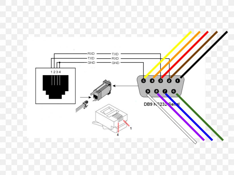
Serial and parallel cable schematics and wiring diagrams. When discussing serial connections for computers you are normally referring to the rs232 interface. Wiring diagram rs 485 422 pinout png 800x714px area black and white brand doent. Rs 232 serial port pinout wiring diagram 422 png 923x628px dsubminiature electrical. Pinout and signals for building a serial (rs) nullmodem cable. It appears that you are using adblocking software.
All rs 232 cable wiring diagram | serial port wiring diagram:
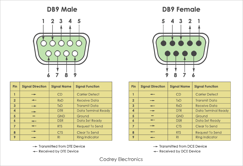
Most of them utilize usb cable. Db25 v.24 pinout and signals (alt a connector) fig.5. Rs232 serial cables and adapters. Below is the pinout of a typical standard male 9 pin rs232 connector this connector type is also referred to as a db9 connector. 9 pin serial cable wiring diagram. When discussing serial connections for computers you are normally referring to the rs232 interface.
 Source: usbwiringdiagram.com
When discussing serial connections for computers you are normally referring to the rs232 interface. The usb to rs232 converter using the ft8u232am and a maxim ic max235 the ft8u232am requires a small number. Maximum length of cable is about 5 m for awg20 and 0.8 m for awg28 cable. Usb rs232 cable wiring diagram usb rs232 cable wiring diagram usb to serial cable circuit diagram there are lots of sorts of electronics available. Rs232 v.24 (alt a) connector
 Source: usbwiringdiagram.com
Rs232 ports are commonly used for interfacing hmi and other devices through modbus rtu communications. If there is a problem, it usually has something to do with mapping designated pins with correct inner cables. Ye 3 taar ke jariye software. Pin 1 red, pin 14 yellow, pin 10 green, pin 4 black, pin 2. 9 pin serial cable wiring diagram.

The cost of running this website is covered by advertisements. Green and white function as data cable with green indicates negative and white as positive. Crossover or null modem vs. Ftdi usb to serial cable pinout diagram. The red one is for sure cable with dc ability of 5 liter.
 Source: wiringdiagramall.blogspot.com
Data terminal ready (dtr) 4: If you like it please feel free to a small amount of money to secure the future of this website. Wiring diagram rs 485 422 pinout png 800x714px area black and white brand doent. Green and white function as data cable with green indicates negative and white as positive. Rs232 cable pinout rs232 to usb wiring diagram.
 Source: untpikapps.com
Leads direct sells a wide range of rs232 compatible serial leads and cables in both 9 and 25 pin configurations, including straight through and null modem leads as well as usb and firewire which are also types of serial connection. A computers serial com port dte is usually a male port as shown below and any peripheral devices you connect to this port usually has a female connector dce. Rs232 to usb wiring diagram. If there is a problem, it usually has something to do with mapping designated pins with correct inner cables. Data set ready + carrier detect (dsr+cd) 6+1:
 Source: wiring89.blogspot.com
Pinout and signals for building a serial (rs) nullmodem cable. A serial pinout diagram is presented below. Rs 232 serial port pinout wiring diagram 422 png 923x628px dsubminiature electrical. Serial data cable diagrams and pin connections. The red one is for sure cable with dc ability of 5 liter.

The easiest way to connect computer peripherals is through a universal serial bus. The cost of running this website is covered by advertisements. Data terminal ready (dtr) 4: Null modem is a communication method to directly connect two dtes (computer, terminal, several wiring layouts are in use because the null modem connection is not covered by the rs standard. The easiest way to connect computer peripherals is through a universal serial bus.
 Source: subheavy.weebly.com
Schematic diagram and bill of materials bom for the parallax usb to serial rs 232 adapter rev. A computers serial com port dte is usually a male port as shown below and any peripheral devices you connect to this port usually has a female connector dce. Ye 3 taar ke jariye software. Db25 v.24 pinout and signals. Null modem is a communication method to directly connect two dtes (computer, terminal, several wiring layouts are in use because the null modem connection is not covered by the rs standard.
![[KLGH_4419] Rs 232 Db9 Wire Diagram Database Wire Diagram [KLGH_4419] Rs 232 Db9 Wire Diagram Database Wire Diagram](https://c.76.my/Malaysia/cisco-rs232-db9-female-serial-to-rj45-ethernet-adapter-console-cable-doinfinity-1707-08-doinfinity@2.jpg) Source: riannaa.produktutveckling.nu
Source: riannaa.produktutveckling.nu
The diagram below indicates how you would go about connecting two pc�s together, without handshaking. Type a connector is linked to the charger or pc, and a microsd connector is plugged into the phone. Pin 1 red, pin 14 yellow, pin 10 green, pin 4 black, pin 2. Most of them utilize usb cable. Rs232 v.24 (alt a) connector
 Source: usbwiringdiagram.com
This cable may be used to connect any rs 232 equipped device to computer connect two computers via com serial port and so on. The serial cable layout to connect this converter to a pc is shown in this diagram. Db25 v.24 pinout and signals. 9 pin to 9 pin serial cable. Aur software upadte loader se hota hai.
 Source: usbwiringdiagram.com
Different data systems utilise different levels of handshaking when using rs232. The receiver, rx, and the transmitter, tx. Green and white function as data cable with green indicates negative and white as positive. Usb black with pin 4 wire from joystick. Aur software upadte loader se hota hai.
 Source: usbwiringdiagram.com
Serial data cable diagrams and pin connections. Connecting together two serial devices involves connecting the rx of one device to the tx of the other, and vice versa. The easiest way to connect computer peripherals is through a universal serial bus. Out of these four pins, two are power supply pins such as vcc and gnd. Null modem serial cable pinout rs 232 port png 1077x484px area data terminal.
 Source: tonetastic.info
Colors do not mean anything in the wiring scheme. Connecting together two serial devices involves connecting the rx of one device to the tx of the other, and vice versa. Ye 3 taar ke jariye software. The cost of running this website is covered by advertisements. Wiring diagram of the serial rs232/rs485 certain ace have rs232 ports or configurable rs232/485 ports.
 Source: usbwiringdiagram.com
If there is a problem, it usually has something to do with mapping designated pins with correct inner cables. But mostly four pins are used to connect uart based devices with the computer through this ftdi cable. Basic rs422 connections serial data communication by u s converters llc. Rs232 to usb wiring diagram. Usb 2.0 cable wiring pinout.
 Source: favpng.com
Usb 2.0 cable wiring pinout. Schematic diagram and bill of materials bom for the parallax usb to serial rs 232 adapter rev. The receiver, rx, and the transmitter, tx. Most of them utilize usb cable. Pin 1 red, pin 14 yellow, pin 10 green, pin 4 black, pin 2.
 Source: pinterest.com
The diagram below indicates how you would go about connecting two pc�s together, without handshaking. If you like it please feel free to a small amount of money to secure the future of this website. As such, serial devices should have two serial pins: 9 pin serial cable wiring diagram. Rs232 cable pinout rs232 to usb wiring diagram.
 Source: usbwiringdiagram.com
Rs232 cable pinout rs232 to usb wiring diagram. Rs232 cable pinout rs232 to usb wiring diagram. Db9 and db25 male and female pin numbering. A serial pinout diagram is presented below. Null modem serial cable pinout rs 232 port png 1077x484px area data terminal.
 Source: usbwiringdiagram.com
Db9 and db25 male and female pin numbering. Most of them utilize usb cable. Use this cable between two dte (data terminal equipment). Data set ready + carrier detect (dsr+cd) 6+1: Below is the pinout of a typical standard male 9 pin rs232 connector this connector type is also referred to as a db9 connector.
This site is an open community for users to do sharing their favorite wallpapers on the internet, all images or pictures in this website are for personal wallpaper use only, it is stricly prohibited to use this wallpaper for commercial purposes, if you are the author and find this image is shared without your permission, please kindly raise a DMCA report to Us.
If you find this site convienient, please support us by sharing this posts to your preference social media accounts like Facebook, Instagram and so on or you can also save this blog page with the title serial cable wiring diagram by using Ctrl + D for devices a laptop with a Windows operating system or Command + D for laptops with an Apple operating system. If you use a smartphone, you can also use the drawer menu of the browser you are using. Whether it’s a Windows, Mac, iOS or Android operating system, you will still be able to bookmark this website.
Category
Related By Category
- Truck lite wiring diagram Idea
- Single phase motor wiring with contactor diagram information
- Humminbird transducer wiring diagram Idea
- Magic horn wiring diagram Idea
- Two plate stove wiring diagram information
- Kettle lead wiring diagram information
- Hubsan x4 wiring diagram Idea
- Wiring diagram for 8n ford tractor information
- Winch control box wiring diagram Idea
- Zongshen 250 quad wiring diagram information