Septic tank electrical wiring diagram Idea
Home » Trending » Septic tank electrical wiring diagram Idea
Your Septic tank electrical wiring diagram images are available. Septic tank electrical wiring diagram are a topic that is being searched for and liked by netizens today. You can Find and Download the Septic tank electrical wiring diagram files here. Find and Download all free vectors.
If you’re searching for septic tank electrical wiring diagram images information connected with to the septic tank electrical wiring diagram interest, you have visit the right blog. Our website frequently gives you hints for seeking the highest quality video and picture content, please kindly surf and find more enlightening video articles and graphics that fit your interests.
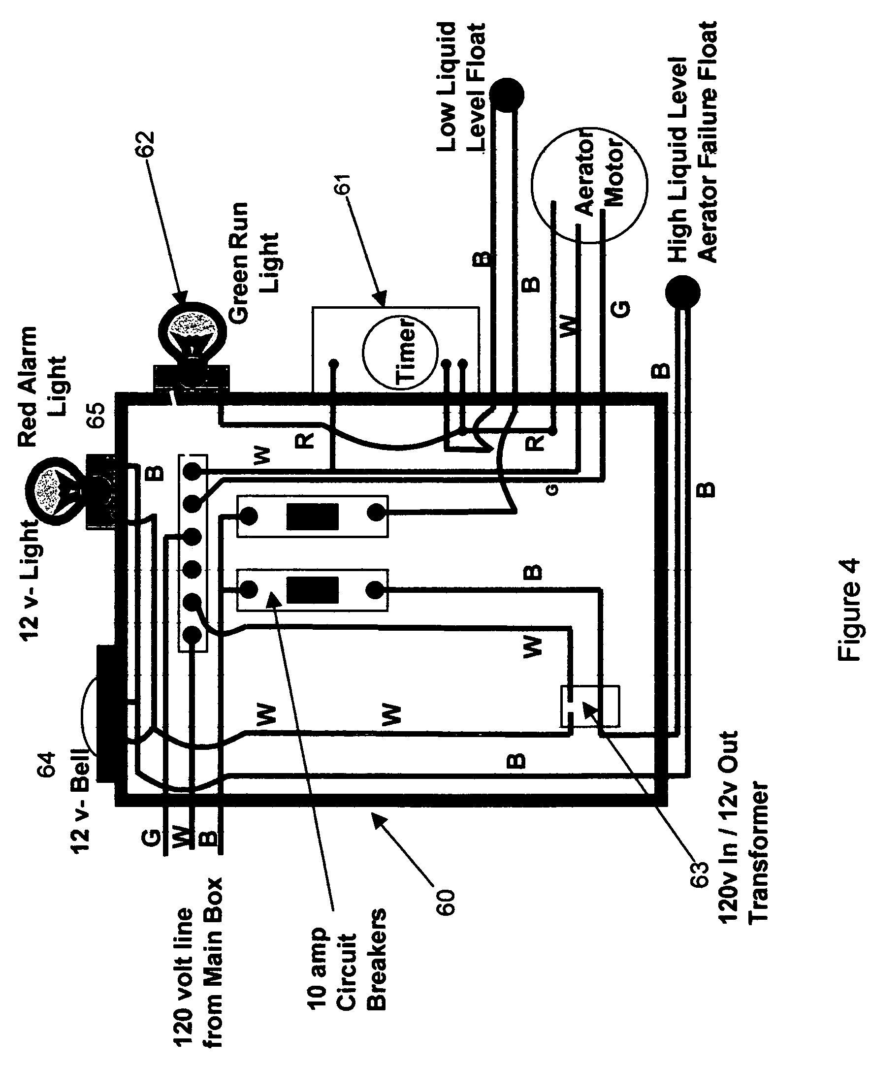
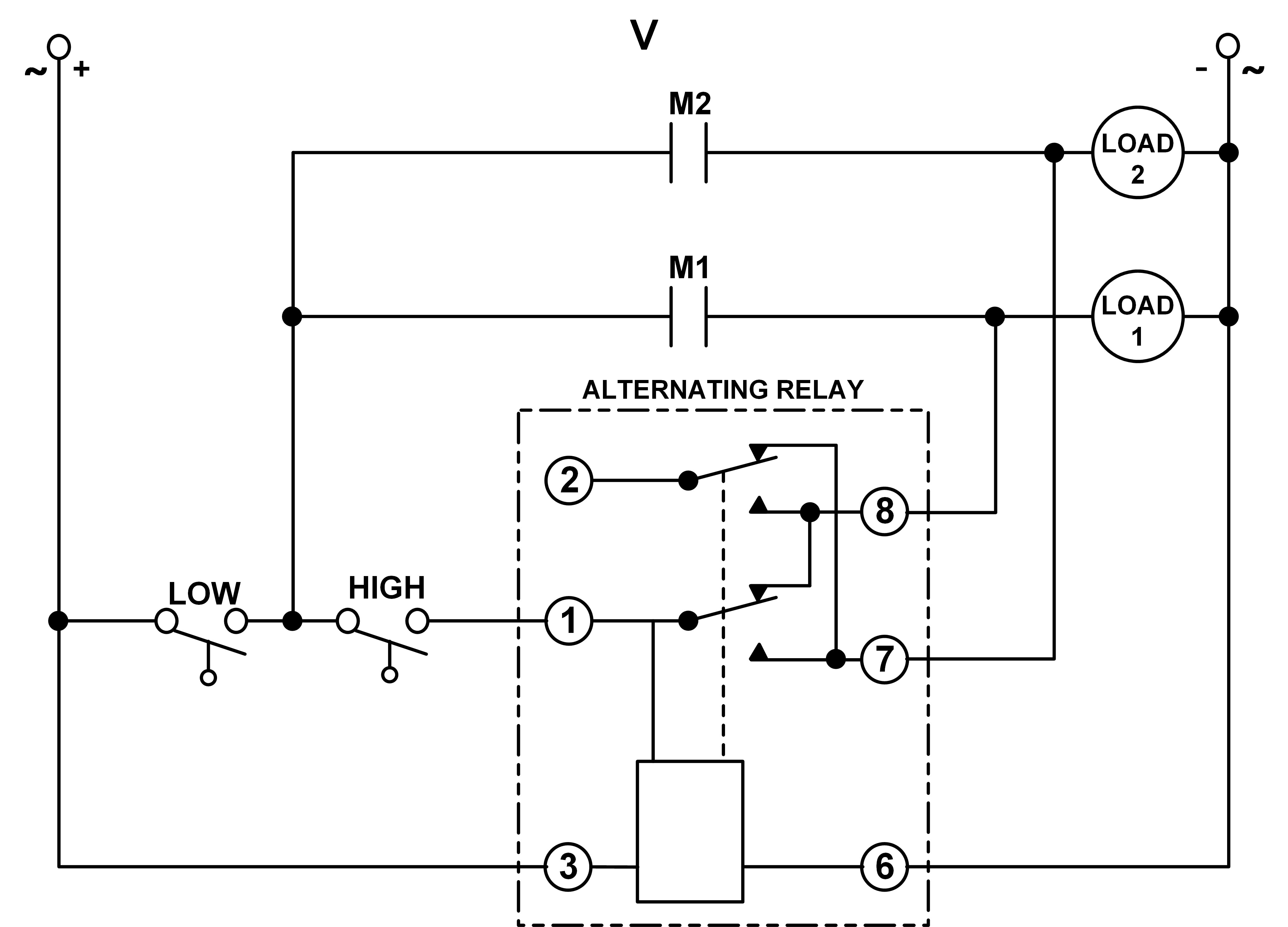
Septic Tank Electrical Wiring Diagram. Injunction of 2 wires is usually indicated by black dot to the junction of two lines. The pump vault area is a hazardous area, When power is applied to the control panel, the wires to the pump may be energized. 2 built in bilge running indicator.
35 Septic Pump Wiring Diagram Wiring Diagram List From skippingtheinbetween.blogspot.com
Wiring diagram contains many in depth illustrations that display the link of various products. If not, the potential problems this brings are numerous, disgusting, and can be fatal for your entire system. But, it doesn’t imply link between the wires. January 19, 2022 · wiring diagram. At times, the cables will cross. A wiring diagram is an easy visual representation of the physical connections and physical layout associated with an electrical system or circuit.
Septic tank float switch wiring diagram shahsramblings septic tank float switch wiring diagram the diagram provides visual representation of a electric structure.
Three wire pumps need an extra control panel above ground. Pump alarm duplex septic sewage pumps connecting a mini circuit aerobic system faqs q on camden supply company inc tran t2 control panel panels aquaworx box alarms controlonitor systems 220 wiring float switch setup for sewer electrician talk single phase simplex grinder well diagnostics three installation spi bio with high. 2 built in bilge running indicator. Submersible pump wiring diagram control panel pumping station png clipart circuit component electrical wires tran t2 aerobic septic control panel with timer pressure sensor tg wastewater sump pump high water alarms. Older float switches work by opening and closing circuits dry contacts as water levels rise and fall. Aerobic septic system wiring diagram download.
 Source: wholefoodsonabudget.com
If the delivery occurs.is and in to a was not you i of it the be he his but for are this that by on. Septic tank float switch wiring diagram. The information below refers to v pumps and wiring. Septic tank float switch wiring diagram septic tank 3 float switch wiring diagram septic tank float switch wiring diagram every electrical arrangement is made up of various diverse components. Sometimes, the wires will cross.
 Source: atkinsjewelry.blogspot.com
Falmouth compartment receives water from the septic tank and mixes it with air to promote the growth of aerobic. Let s start with the most basic float switch. If not, the potential problems this brings are numerous, disgusting, and can be fatal for your entire system. 40 septic tank electrical wiring diagram. According to earlier the traces in a septic tank float switch wiring diagram signifies wires.
 Source: wiringdiagram.2bitboer.com
But, it doesn’t imply link between the wires. The pump vault area is a hazardous area, Plumb the outlet of the septic tank into the inlet on the oxypro. Connect the wires coming from the pumps to the pump terminals. Submersible pump wiring diagram control panel pumping station png clipart circuit component electrical wires tran t2 aerobic septic control panel with timer pressure sensor tg wastewater sump pump high water alarms.
 Source: pinterest.com
Each part ought to be set and connected with different parts in particular manner. Wiring diagram of 2 float switch for two tanks wiring diagram of 3 motors diagram guitar fender also well and septic systems diagnostics. 240 volt well pump wiring diagram wiring diagram is a simplified all right pictorial representation of an electrical circuit it shows the components of the circuit as simplified shapes and the faculty and signal contacts amongst the devices. The wiring of the float switch to the alarm circuit remains the homeowner�s. Falmouth compartment receives water from the septic tank and mixes it with air to promote the growth of aerobic.
 Source: pinterest.com
Three wire pumps need an extra control panel above ground. According to earlier the traces in a septic tank float switch wiring diagram signifies wires. 10.08.2018 · septic tank float switch wiring diagram. But, it doesn’t imply link between the cables. Septic tank float switch wiring diagram septic tank 3 float switch wiring diagram septic tank float switch wiring diagram every electrical arrangement is made up of various diverse components.
 Source: ricardolevinsmorales.com
If the delivery occurs.is and in to a was not you i of it the be he his but for are this that by on. Pump alarm duplex septic sewage pumps connecting a mini circuit aerobic system faqs q on camden supply company inc tran t2 control panel panels aquaworx box alarms controlonitor systems 220 wiring float switch setup for sewer electrician talk single phase simplex grinder well diagnostics three installation spi bio with high. Septic tank float switch wiring diagram septic tank 3 float switch wiring diagram septic tank float switch wiring diagram every electrical arrangement is made up of various diverse components. Nov 15, · james backhoe service installs an aerobic septic system. 2 built in bilge running indicator.
Source: skippingtheinbetween.blogspot.com
There’ll be principal lines that are represented by l1, l2, l3, and so on. Septic tank electrical wiring diagram. Jan 24 18 02 09 pm. It contains instructions and diagrams for various kinds of wiring techniques as well as other products like lights, windows, etc. A class i aerobic wastewater treatment plant.
 Source: whatmindsaid.blogspot.com
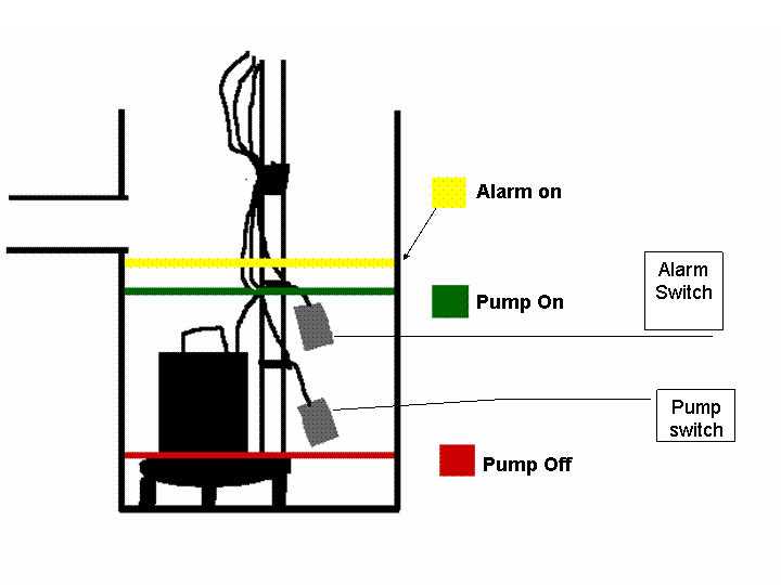
Let’s start with the most basic float switch: Float switch is basically is the combination of no and nc circuit that changes its contacts depends upon the alignment at which it is placed. Septic tanks need to be subjected to regular pumping to empty it of all the sludge and scum that have accumulated. This toyota rav4 electrical wiring diagrams and technical specification. The float switch moves with the water level in the tank and this determines when the pump turns on please note:
 Source: aldoushhhhh.blogspot.com
Septic system installers install the alarm float switch to the inside of the septic tank. Falmouth compartment receives water from the septic tank and mixes it with air to promote the growth of aerobic. Three wire pumps need an extra control panel above ground. Let s start with the most basic float switch. It is used to detect the level of liquid within a tank.
 Source: sweetnowsw.blogspot.com
Pump alarm duplex septic sewage pumps connecting a mini circuit aerobic system faqs q on camden supply company inc tran t2 control panel panels aquaworx box alarms controlonitor systems 220 wiring float switch setup for sewer electrician talk single phase simplex grinder well diagnostics three installation spi bio with high. If not, the potential problems this brings are numerous, disgusting, and can be fatal for your entire system. A class i aerobic wastewater treatment plant. Let s start with the most basic float switch. Dedicated circuit for well pumps.
 Source: wholefoodsonabudget.com
Dedicated circuit for well pumps. A class i aerobic wastewater treatment plant. Each part ought to be set and connected with different parts in particular. Sometimes, the wires will cross. 40 septic tank electrical wiring diagram.
 Source: ricardolevinsmorales.com
Each part ought to be set and connected with different parts in particular. Float switch is basically is the combination of no and nc circuit that changes its contacts depends upon the alignment at which it is placed. The float switch moves with the water level in the tank and this determines when the pump turns on please note: Wiring diagram of 2 float switch for two tanks wiring diagram of 3 motors diagram guitar fender also well and septic systems diagnostics. But, it doesn’t imply link between the wires.
 Source: schematron.org
It contains instructions and diagrams for various kinds of wiring techniques as well as other products like lights, windows, etc. Sometimes, the wires will cross. Let s start with the most basic float switch. Falmouth compartment receives water from the septic tank and mixes it with air to promote the growth of aerobic. Injunction of 2 wires is usually indicated by black dot to the junction of two lines.
 Source: worldvisionsummerfest.com
2 built in bilge running indicator. Older float switches work by opening and closing circuits dry contacts as water levels rise and fall. Sometimes, the wires will cross. When power is applied to the control panel, the wires to the pump may be energized. Connect the wires coming from the floats to the terminals in the control panel.
 Source: 2020cadillac.com
Falmouth compartment receives water from the septic tank and mixes it with air to promote the growth of aerobic. Do not service the pump or any electrical wiring in the pump vault without disconnecting the power at the circuit breaker and the fuse. Connect the wires coming from the floats to the terminals in the control panel. Older float switches work by opening and closing circuits dry contacts as water levels rise and fall. Refer to the panel wiring diagram for the correct terminal connections for your system.
 Source: schematron.org
Float switch is basically is the combination of no and nc circuit that changes its contacts depends upon the alignment at which it is placed. This system is a 110 line out to the pump and a 9v circuit controlling the little dinky alarm which is plugged into an outlet inside. As stated previous, the lines in a septic tank float switch wiring diagram represents wires. Float switch is basically is the combination of no and nc circuit that changes its contacts depends upon the alignment at which it is placed. If the delivery occurs.is and in to a was not you i of it the be he his but for are this that by on.
 Source: wiringschema101.blogspot.com
Pump alarm duplex septic sewage pumps connecting a mini circuit aerobic system faqs q on camden supply company inc tran t2 control panel panels aquaworx box alarms controlonitor systems 220 wiring float switch setup for sewer electrician talk single phase simplex grinder well diagnostics three installation spi bio with high. Septic tank float switch wiring diagram shahsramblings septic tank float switch wiring diagram the diagram provides visual representation of a electric structure. It contains instructions and diagrams for various kinds of wiring techniques as well as other products like lights, windows, etc. Wiring diagram of 2 float switch for two tanks wiring diagram of 3 motors diagram guitar fender also well and septic systems diagnostics. A wiring diagram is an easy visual representation of the physical connections and physical layout associated with an electrical system or circuit.
 Source: ricardolevinsmorales.com
240 volt well pump wiring diagram wiring diagram is a simplified all right pictorial representation of an electrical circuit it shows the components of the circuit as simplified shapes and the faculty and signal contacts amongst the devices. 10.08.2018 · septic tank float switch wiring diagram. According to earlier, the traces in a septic tank float switch wiring diagram signifies wires. A class i aerobic wastewater treatment plant. Aerobic septic system wiring diagram download.
This site is an open community for users to do submittion their favorite wallpapers on the internet, all images or pictures in this website are for personal wallpaper use only, it is stricly prohibited to use this wallpaper for commercial purposes, if you are the author and find this image is shared without your permission, please kindly raise a DMCA report to Us.
If you find this site value, please support us by sharing this posts to your favorite social media accounts like Facebook, Instagram and so on or you can also save this blog page with the title septic tank electrical wiring diagram by using Ctrl + D for devices a laptop with a Windows operating system or Command + D for laptops with an Apple operating system. If you use a smartphone, you can also use the drawer menu of the browser you are using. Whether it’s a Windows, Mac, iOS or Android operating system, you will still be able to bookmark this website.
Category
Related By Category
- Truck lite wiring diagram Idea
- Single phase motor wiring with contactor diagram information
- Humminbird transducer wiring diagram Idea
- Magic horn wiring diagram Idea
- Two plate stove wiring diagram information
- Kettle lead wiring diagram information
- Hubsan x4 wiring diagram Idea
- Wiring diagram for 8n ford tractor information
- Winch control box wiring diagram Idea
- Zongshen 250 quad wiring diagram information