Septic pump wiring diagram Idea
Home » Trending » Septic pump wiring diagram Idea
Your Septic pump wiring diagram images are available. Septic pump wiring diagram are a topic that is being searched for and liked by netizens today. You can Find and Download the Septic pump wiring diagram files here. Download all free photos.
If you’re looking for septic pump wiring diagram pictures information connected with to the septic pump wiring diagram topic, you have visit the right site. Our website always provides you with suggestions for downloading the highest quality video and image content, please kindly surf and find more enlightening video articles and images that match your interests.
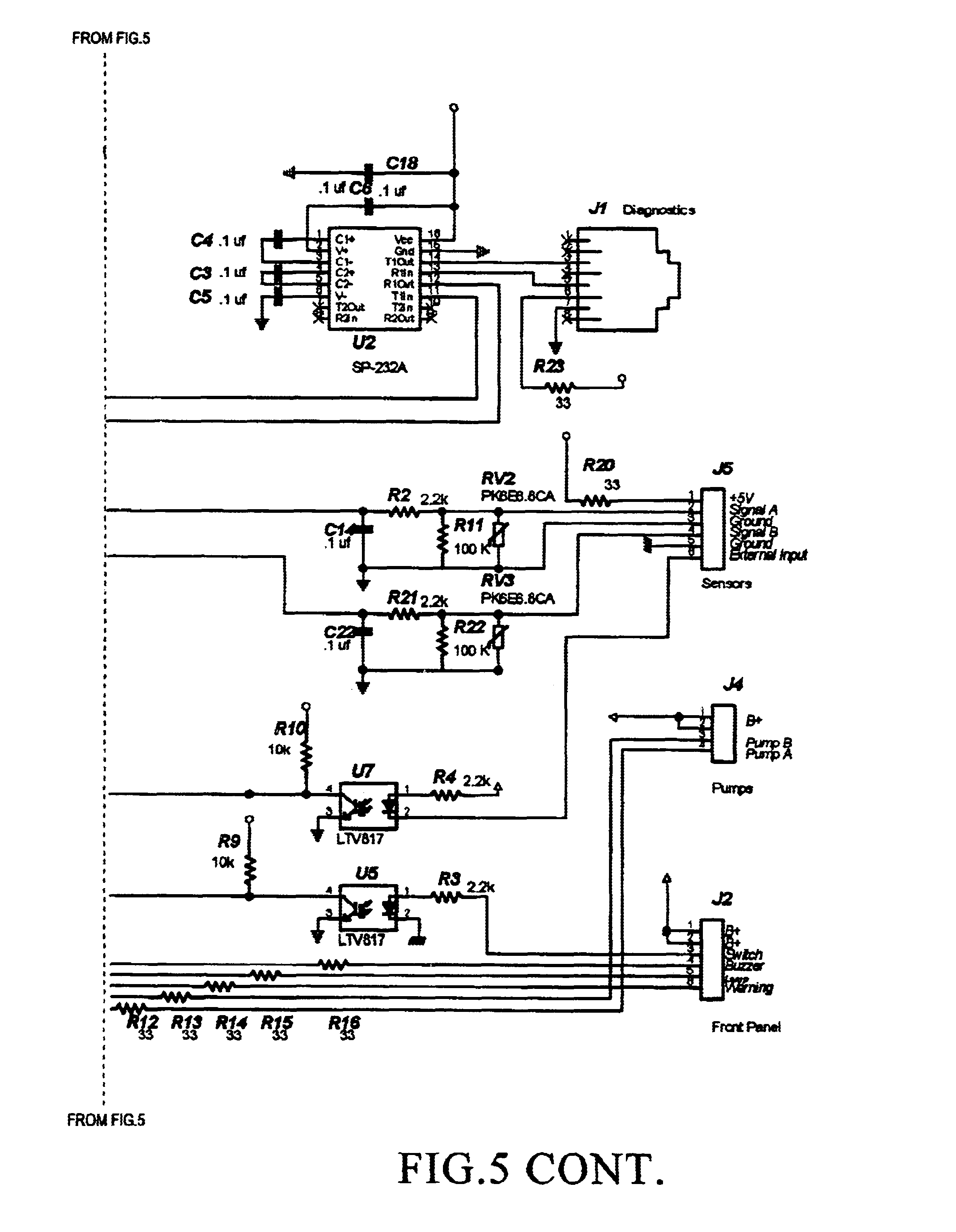
Septic Pump Wiring Diagram. The middle liquid layer (effluent) then exits the tank and into the drainfield. Below is an excellent video tutorial from unitedstatesofbuild. It shows the components of the circuit as simplified shapes, as well as the power as well as signal links between the tools. The previous home owner had buried the cable under ground and the over the years the cable deteriorated and corroded and eventually shorted out.
 Septic Pump Wiring Diagram Free Wiring Diagram From ricardolevinsmorales.com
The information below refers to v pumps and. According to earlier the traces in a septic tank float switch wiring diagram signifies wires. The best unusual is always to use a verified and accurate grinder pump wiring diagram that’s provided from a trusted source. Septic pump alarm wiring diagram. The information below refers to v pumps and wiring. Below is an excellent video tutorial from unitedstatesofbuild.
How to care for a septic system septic system septic.
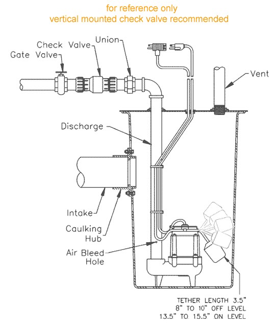
Below is a diagram of what is described in the paragraph above.septic solutions® carries a large selection of septic tank alarms, control panels, and float switches. The drainfield is a shallow (covered) excavation ideally in unsaturated soil. A circuit is usually composed by various components. Below is a diagram of what is described in the paragraph above.septic solutions® carries a large selection of septic tank alarms, control panels, and float switches. I want to put a 20amp circuit in the conduit with a. It shows the components of the circuit as simplified shapes, as well as the power as well as signal links between the tools.
 Source: pinterest.com
Diagram 2 float pump control septic wiring diy diagrams how to wire a submersible aerobic system bmw 650i fuse tank 2017. Now look to see if the breaker takes up two breaker spaces or one. Septic system lift pump and the float switch. The previous home owner had buried the cable under ground and the over the years the cable deteriorated and corroded and eventually shorted out. The diagram below references a v pump and wiring.
 Source: aldoushhhhh.blogspot.com
Septic tank electrical wiring diagram. Now look to see if the breaker takes up two breaker spaces or one. For septic system control and alarm. Wiring diagram for float switch fresh septic tank download of 2 submersible pump submersible jet pump. Septic pump alarm wiring diagram.
 Source: ricardolevinsmorales.com
The first component is symbol that indicate electric element in the circuit. Brandywine septic services inc pump alarm 610 869 0443 duplex sewage pumps installation guide to how wire a submersible aerobic system septicpro engineering maintenance in swanzey keene nharea works tank pumping treatment others. The drainfield is a shallow (covered) excavation ideally in unsaturated soil. The first component is symbol that indicate electric element in the circuit. Installation instructions, wiring diagrams, etc.
 Source: wiringschema101.blogspot.com
Hvac float switch wiring diagram wiring diagram is a simplified satisfactory pictorial representation of an electrical circuit. Septic pump alarm wiring diagram wiring diagram and schematics wiring diagram and schematics this place is a growing library of the schematics, wiring diagrams and technical photos According to earlier the traces in a septic tank float switch wiring diagram signifies wires. Brandywine septic services inc pump alarm 610 869 0443 duplex sewage pumps installation guide to how wire a submersible aerobic system septicpro engineering maintenance in swanzey keene nharea works tank pumping treatment others. Electrical wiring leads for the grinder pump and septic pump alarm;
 Source: ricardolevinsmorales.com
Refer to the panel wiring diagram for the correct terminal connections for your system. By admin | october 21, 2017. Assortment of septic pump wiring diagram. Click on the image to enlarge, and then save it to your computer by right clicking on the image. Diagram 2 float pump control septic wiring diy diagrams how to wire a submersible aerobic system bmw 650i fuse tank 2017.
 Source: wholefoodsonabudget.com
The sewage grinder tank must be vented either directly or through the inlet pipe and within 4 ft. Angelo on july 27, 2021. Johnson bilge pump float switch wiring diagram. It reveals the elements of the circuit as simplified shapes and also the power as well as signal links between the tools. According to earlier the traces in a septic tank float switch wiring diagram signifies wires.
 Source: mamvic.com
Of the tank to a. Septic tank electrical wiring diagram.electrical schematic and wiring diagram. Brandywine septic services inc pump alarm 610 869 0443 duplex sewage pumps installation guide to how wire a submersible aerobic system septicpro engineering maintenance in swanzey keene nharea works tank pumping treatment others. 120vac, single phase for a 120 vac motor, 2 wire submersible well pump wiring diagram a newbie s overview of circuit diagrams.
 Source: faceitsalon.com
Refer to the panel wiring diagram for the correct terminal connections. These instructions will probably be easy to comprehend and use. The sewage grinder tank must be vented either directly or through the inlet pipe and within 4 ft. Wiring diagram arrives with several easy to stick to wiring diagram guidelines. 10.08.2018 · septic tank float switch wiring diagram.
 Source: sweetnowsw.blogspot.com
The diagram below references a v pump and wiring. I print out the schematic plus highlight the routine im diagnosing to make sure. How to construct a small septic system septic system. Wiring diagram arrives with several easy to stick to wiring diagram guidelines. Johnson bilge pump float switch wiring diagram.
 Source: pinterest.com
The previous home owner had buried the cable under ground and the over the years the cable deteriorated and corroded and eventually shorted out. Below is a diagram of what is described in the paragraph above.septic solutions® carries a large selection of septic tank alarms, control panels, and float switches. For septic system control and alarm. The best unusual is always to use a verified and accurate grinder pump wiring diagram that’s provided from a trusted source. If playback doesn�t begin shortly, try restarting your device.
 Source: ricardolevinsmorales.com
Start at the breaker panel. See the electrical wiring video #2 below: Unique wiring diagram for jet pump diagram diagramtemplate diagramsample Installation instructions, wiring diagrams, etc. 3 backlit bilge rocker switch wiring diagram.
 Source: wiringdiagram.2bitboer.com
12 awesome wiring diagram for 220 volt submersible pump ideas bacamajalah electrical diagram submersible pump ceiling fan with remote. By admin | october 21, 2017. The diagram below references a v pump and wiring. Standard with most common being black blue brown. Below is an excellent video tutorial from unitedstatesofbuild.

Standard with most common being black blue brown. The diagram below references a v pump and wiring. Johnson bilge pump float switch wiring diagram. 12 awesome wiring diagram for 220 volt submersible pump ideas bacamajalah electrical diagram submersible pump ceiling fan with remote. Electrical wiring leads for the grinder pump and septic pump alarm;
 Source: adinaporter.com
Over 95% of aerobic septic systems use v rather than v. Refer to the panel wiring diagram for the correct terminal connections. Connect the incoming power to the panel. Diagram 2 float pump control septic wiring diy diagrams how to wire a submersible aerobic system bmw 650i fuse tank 2017. 2 wire submersible well pump wiring diagram a newbie s overview of circuit diagrams.
 Source: ricardolevinsmorales.com
Pump alarm duplex septic sewage pumps aerobic system faqs q a on spex 1 sump and exerciser float switch installation wiring tank alarms contractor talk control panels aquaworx box manual ppt single phase simplex grinder camden supply company inc 220 setup for. There are just two things that will be found in almost any septic tank float switch wiring diagram. I print out the schematic plus highlight the routine im diagnosing to make sure. Submersible pump 240 volt well pump wiring diagram submersible well pump wiring diagrams. Connect the wires coming from the pumps to the pump terminals.
 Source: pinterest.com
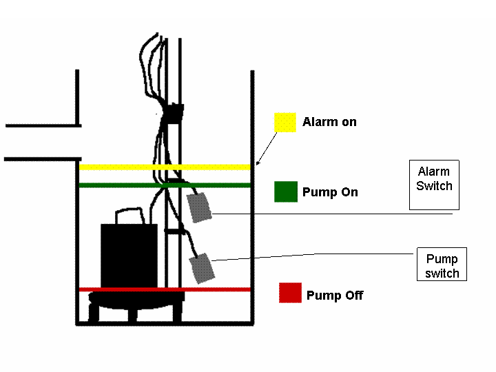
The float switch moves with the water level in the tank and this determines when the pump turns on please note: Over 95% of aerobic septic systems use v rather than v. If playback doesn�t begin shortly, try restarting your device. Looking for ideas on wiring a septic pump. The information below refers to v pumps and.
 Source: schematron.org
These instructions will probably be easy to comprehend and use. Wiring diagram arrives with several easy to stick to wiring diagram guidelines. Refer to the panel wiring diagram for the correct terminal connections for your system. See the electrical wiring video #2 below: Another thing that you will find a circuit diagram would be traces.
 Source: worldvisionsummerfest.com
Septic pump alarm wiring diagram. I was wanting to know if it is permissible by code to run one conduit. Assortment of septic pump wiring diagram. The diagram below references a v pump and wiring. 4 pvc tank inlet for connection to building drains served by the pump;
This site is an open community for users to share their favorite wallpapers on the internet, all images or pictures in this website are for personal wallpaper use only, it is stricly prohibited to use this wallpaper for commercial purposes, if you are the author and find this image is shared without your permission, please kindly raise a DMCA report to Us.
If you find this site serviceableness, please support us by sharing this posts to your preference social media accounts like Facebook, Instagram and so on or you can also bookmark this blog page with the title septic pump wiring diagram by using Ctrl + D for devices a laptop with a Windows operating system or Command + D for laptops with an Apple operating system. If you use a smartphone, you can also use the drawer menu of the browser you are using. Whether it’s a Windows, Mac, iOS or Android operating system, you will still be able to bookmark this website.
Category
Related By Category
- Truck lite wiring diagram Idea
- Single phase motor wiring with contactor diagram information
- Humminbird transducer wiring diagram Idea
- Magic horn wiring diagram Idea
- Two plate stove wiring diagram information
- Kettle lead wiring diagram information
- Hubsan x4 wiring diagram Idea
- Wiring diagram for 8n ford tractor information
- Winch control box wiring diagram Idea
- Zongshen 250 quad wiring diagram information