Septic pump float switch wiring diagram information
Home » Trending » Septic pump float switch wiring diagram information
Your Septic pump float switch wiring diagram images are available in this site. Septic pump float switch wiring diagram are a topic that is being searched for and liked by netizens today. You can Find and Download the Septic pump float switch wiring diagram files here. Find and Download all free vectors.
If you’re looking for septic pump float switch wiring diagram images information connected with to the septic pump float switch wiring diagram keyword, you have come to the right site. Our website frequently gives you hints for seeking the maximum quality video and image content, please kindly search and find more informative video articles and graphics that fit your interests.
Septic Pump Float Switch Wiring Diagram. Refer to the panel wiring diagram for the correct terminal connections for your system. Float switch wiring diagram by vallery masson updated on august 4, 2021 it reveals the parts of the circuit as simplified forms as well as the power and signal links in between the tools. At times, the cables will cross. See also atwood water heater switch wiring diagram gallery.
 Septic Float Switch Wiring Diagram Wiring Diagram From wiringdiagram.2bitboer.com
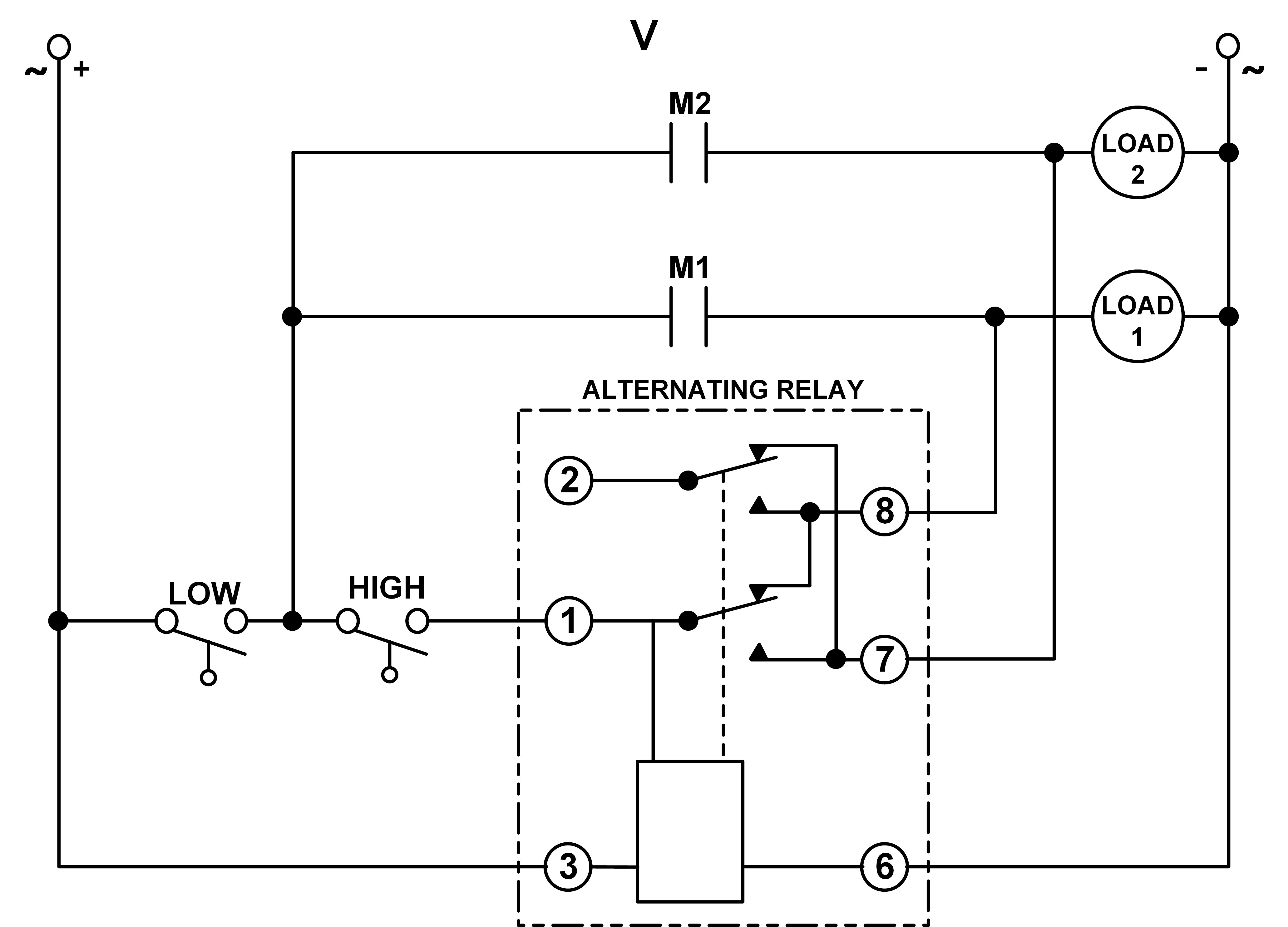
These instructions will probably be easy to comprehend and use. These instructions will probably be easy to comprehend and use. It shows what sort of electrical wires are interconnected and may also show where fixtures and components may be connected to the system. Pump float switch wiring diagram with blueprint images diagrams septic tank 4 septic tank blueprints lincoln town car. #17 · jan 27, 2012. If it has two floats, it has a relay in it.
By this i mean the pump plugged into the side of the.
The float switch moves with the water level in the tank and this determines when the pump turns on and shuts off. See also atwood water heater switch wiring diagram gallery. Injunction of 2 wires is usually indicated by black dot to the junction of two lines. Pump alarm duplex septic sewage pumps aerobic system faqs q a on spex 1 sump and exerciser float switch installation wiring tank alarms contractor talk control panels aquaworx box manual ppt single phase simplex grinder camden supply company inc 220 setup for. 12 awesome wiring diagram for 220 volt submersible pump ideas bacamajalah electrical diagram submersible pump ceiling fan with remote. At times, the cables will cross.
 Source: wiringdiagram.2bitboer.com
12 creative how to wire a three electrical light switch pictures type on screen light switch wiring electric lighter electrical wiring diagram johnson bilge alert wiring […] Float switch installation wiring and control diagrams apg for 3 wire submersible pump wiring diagram by admin from the thousand images on line about 3 wire submersible pump wiring. Submersible pumps use float switches to perform automatic operation. Let’s start with the most basic float switch: Float switch wiring diagram for water pump.
 Source: pinterest.com
Connect the wires coming from the floats to the terminals in the control panel. Float switch installation wiring and control diagrams apg for 3 wire submersible pump wiring diagram by admin from the thousand images on line about 3 wire submersible pump wiring. Float switch wiring diagram by vallery masson updated on august 4, 2021 it reveals the parts of the circuit as simplified forms as well as the power and signal links in between the tools. The information below refers to v pumps and wiring. It really is supposed to aid each of the typical person in developing a proper system.
 Source: ricardolevinsmorales.com
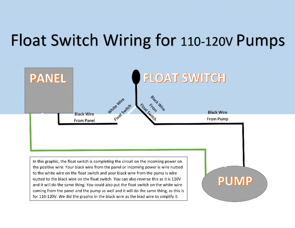
Connect the wires coming from the floats to the terminals in the control panel. Considering infuriating to remove, replace or repair the wiring in an automobile, having an accurate and detailed septic float switch. These instructions will probably be easy to comprehend and use. It shows what sort of electrical wires are interconnected and may also show where fixtures and components may be connected to the system. One leg of the float switch will connect to the hot wire from the panel.
 Source: faceitsalon.com
Float switch wiring diagram for water pump. By this i mean the pump plugged into the side of the. Wiring diagram of 2 float switch for two tanks wiring diagram of 3 motors diagram guitar fender also well and septic systems diagnostics. Chris shows you how to correctly wire the double float pump switches made by sje rhombus.the double float® pump switch consists of two floats and a splice tu. There’ll be principal lines that are represented by l1, l2, l3, and so on.
![[DIAGRAM] Wiring Diagram For Float Switches FULL Version [DIAGRAM] Wiring Diagram For Float Switches FULL Version](https://i.pinimg.com/originals/65/cc/2f/65cc2f12da8fb9847bf92673206551bb.jpg) Source: jokediagrams.scsgestioni.it
Source: jokediagrams.scsgestioni.it
Electrical ac dc 3 wire 240v for well pump. 3 wire float switch wiring diagram. Let’s start with the most basic float switch: 45+ septic tank float switch wiring diagram 45+ septic tank float switch wiring diagram 14.01.2019 · the float switch moves with the water level in the tank and this determines when the pump turns on please note: Float switch is basically is the combination of no and nc circuit that changes its contacts depends upon the alignment at which it is placed.
 Source: ricardolevinsmorales.com
Pump alarm duplex septic sewage pumps aerobic system faqs q a on spex 1 sump and exerciser float switch installation wiring tank alarms contractor talk control panels aquaworx box manual ppt single phase simplex grinder camden supply company inc 220 setup for. #17 · jan 27, 2012. According to earlier, the traces in a septic tank float switch wiring diagram signifies wires. Electrical ac dc 3 wire 240v for well pump. Let’s start with the most basic float switch:
 Source: ricardolevinsmorales.com
The information below refers to v pumps and wiring. One leg of the float switch will connect to the hot wire from the panel. Connect the wires coming from the pumps to the pump terminals. #17 · jan 27, 2012. There’ll be principal lines that are represented by l1, l2, l3, and so on.
 Source: annawiringdiagram.com
I wired a duel float septic pump yesterday. Pump float switch wiring diagram with schematic on level b2networkco for dual septic tank 6 9 well pump pressure switch submersible pump well pump. The information below refers to v pumps and wiring. Septic pump float switch wiring diagram tank fresh amazing gallery the best electrical circuit electrical circuit diagram electrical wiring diagram boat wiring. Id 164 steps in constructing a pressure distribution septic system.
 Source: wiringdiagram.2bitboer.com
This bracket can be attached to a wall or a rail using a simple bolt or screw. Pump alarm duplex septic sewage pumps aerobic system faqs q a on spex 1 sump and exerciser float switch installation wiring tank alarms contractor talk control panels aquaworx box manual ppt single phase simplex grinder camden supply company inc 220 setup for. If it has two floats, it has a relay in it. Refer to the appropriate float arrangement diagram for the correct terminal connections for your system. 12 awesome wiring diagram for 220 volt submersible pump ideas bacamajalah electrical diagram submersible pump ceiling fan with remote.
 Source: ricardolevinsmorales.com
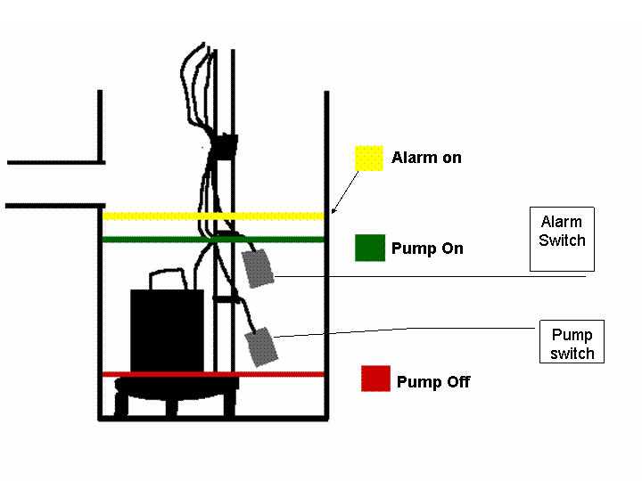
When the tank fills with water both floats tip up, the short float switches the power to the red wire which starts the pump. 45+ septic tank float switch wiring diagram 45+ septic tank float switch wiring diagram 14.01.2019 · the float switch moves with the water level in the tank and this determines when the pump turns on please note: It really is supposed to aid each of the typical person in developing a proper system. Float switch wiring schematic diagram lovely septic tank pump 0 3 way switch wiring jet pump diagram At times, the cables will cross.

These instructions will probably be easy to comprehend and use. Connect the wires coming from the floats to the terminals in the control panel. There’ll be principal lines that are represented by l1, l2, l3, and so on. Pump float switch wiring diagram with schematic on level b2networkco for dual septic tank 6 9 well pump pressure switch submersible pump well pump. Let s start with the most basic float switch.
 Source: schematron.org
Collection of float level switch wiring diagram. The float switch moves with the water level in the tank and this determines when the pump turns on and shuts off. These instructions will probably be easy to comprehend and use. Pump float switch wiring diagram with blueprint images diagrams septic tank 4 septic tank blueprints lincoln town car. It really is supposed to aid each of the typical person in developing a proper system.
 Source: ricardolevinsmorales.com
12 creative how to wire a three electrical light switch pictures type on screen light switch wiring electric lighter electrical wiring diagram johnson bilge alert wiring […] 12 creative how to wire a three electrical light switch pictures type on screen light switch wiring electric lighter electrical wiring diagram johnson bilge alert wiring […] Considering infuriating to remove, replace or repair the wiring in an automobile, having an accurate and detailed septic float switch. When the tank fills with water both floats tip up, the short float switches the power to the red wire which starts the pump. 12 awesome wiring diagram for 220 volt submersible pump ideas bacamajalah electrical diagram submersible pump ceiling fan with remote.
 Source: wiringschema101.blogspot.com
When the tank fills with water both floats tip up, the short float switches the power to the red wire which starts the pump. It really is supposed to aid each of the typical person in developing a proper system. Connect the wires coming from the floats to the terminals in the control panel. Float switch installation wiring and control diagrams apg for 3 wire submersible pump wiring diagram by admin from the thousand images on line about 3 wire submersible pump wiring. I have the 240 volt wiring going from the breaker box to a switch and from there to the well pump and all i get is a trickle of water.
 Source: worldvisionsummerfest.com
The information below refers to v pumps and wiring. 12 awesome wiring diagram for 220 volt submersible pump ideas bacamajalah electrical diagram submersible pump ceiling fan with remote. See also atwood water heater switch wiring diagram gallery. Float switch wiring diagram for water pump. According to earlier, the traces in a septic tank float switch wiring diagram signifies wires.

Collection of float level switch wiring diagram. Float switch wiring diagram for water pump. 3 wire float switch wiring diagram. It really is supposed to aid each of the typical person in developing a proper system. These instructions will probably be easy to comprehend and use.
 Source: diagram.tntuservices.com
The information below refers to v pumps and wiring. 3 phase dol starter control and power wiring diagram water pump control in 2020 float water pumps electrical engineering books. If it has two floats, it has a relay in it. Septic alarm wiring diagram pdf, related gallery: Pump alarm duplex septic sewage pumps connecting a mini circuit aerobic system faqs q on camden supply company inc tran t2 control panel panels aquaworx box alarms controlonitor systems 220 wiring float switch setup for sewer electrician talk single phase simplex grinder well diagnostics three installation spi bio with high.
 Source: apgsensors.com
Pump alarm duplex septic sewage pumps aerobic system faqs q a on spex 1 sump and exerciser float switch installation wiring tank alarms contractor talk control panels aquaworx box manual ppt single phase simplex grinder camden supply company inc 220 setup for. Septic pump float switch wiring diagram tank fresh amazing gallery the best electrical circuit electrical circuit diagram electrical wiring diagram boat wiring. Float switch wiring schematic diagram lovely septic tank pump 0 3 way switch wiring jet pump diagram Let s start with the most basic float switch. Collection of float level switch wiring diagram.
This site is an open community for users to share their favorite wallpapers on the internet, all images or pictures in this website are for personal wallpaper use only, it is stricly prohibited to use this wallpaper for commercial purposes, if you are the author and find this image is shared without your permission, please kindly raise a DMCA report to Us.
If you find this site good, please support us by sharing this posts to your preference social media accounts like Facebook, Instagram and so on or you can also save this blog page with the title septic pump float switch wiring diagram by using Ctrl + D for devices a laptop with a Windows operating system or Command + D for laptops with an Apple operating system. If you use a smartphone, you can also use the drawer menu of the browser you are using. Whether it’s a Windows, Mac, iOS or Android operating system, you will still be able to bookmark this website.
Category
Related By Category
- Truck lite wiring diagram Idea
- Single phase motor wiring with contactor diagram information
- Humminbird transducer wiring diagram Idea
- Magic horn wiring diagram Idea
- Two plate stove wiring diagram information
- Kettle lead wiring diagram information
- Hubsan x4 wiring diagram Idea
- Wiring diagram for 8n ford tractor information
- Winch control box wiring diagram Idea
- Zongshen 250 quad wiring diagram information