Schneider vfd control wiring diagram Idea
Home » Trend » Schneider vfd control wiring diagram Idea
Your Schneider vfd control wiring diagram images are ready. Schneider vfd control wiring diagram are a topic that is being searched for and liked by netizens now. You can Find and Download the Schneider vfd control wiring diagram files here. Get all free photos and vectors.
If you’re looking for schneider vfd control wiring diagram pictures information connected with to the schneider vfd control wiring diagram topic, you have visit the right blog. Our website frequently gives you hints for seeking the highest quality video and image content, please kindly surf and find more enlightening video articles and graphics that match your interests.
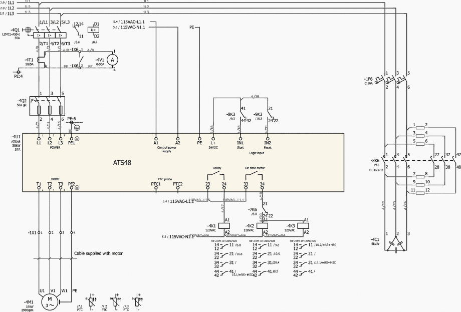
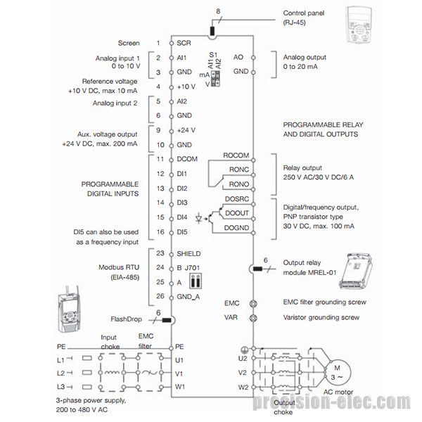
Schneider Vfd Control Wiring Diagram. Typically, these will be on the same 24 vdc system as the remainder of the control system devices. Single line connections scientific read figure 2 1 sheet 4 nile automation system posts facebook 3 phase induction schneider electric switches relays authorized distributor newark what is circuit its operation types applications complete drawing ga iga bom upwork standard. Phase 2 l1, l2, l3 ground, when used (4) multiple vfds ground should be connected to the earth respectively, do not make the ground wire form a loop.
 Wiring For Switch And Contactor Coil Wiring Diagram Schemas From wiringschemas.blogspot.com
This is a complete tutorial about plc ladder logic to control variable frequency drive (vfd) for motor speed control with speed selection from field local panel or scada graphics. Vauxhall insignia engine diagram | wiring diagram schneider contactor | thhnthwn wire | wiring diagram for 20 hp kohler engine. 100% of nominal motor torque drive controllers ≤ atv31•018m2: Vfd dol changeover circuit bypass arrangement electrical4u soft starter 132kw 380v manufacturers and suppliers china factory aubo electric is it possible to start 3 pumps with one when pump 1 running should put over contactor then 2 on star delta cr4 discussion thread 180 hp small power digital online. 13.10.2018 13.10.2018 4 comments on altivar 61 control wiring diagram many parts in this variable speed drive, including printed wiring boards, operate at line voltage disconnect all power including external control power that may be present before altivar 61 drives up to ratings atv61hd15m3x, atv61hd18n4 and this function requires the use of. Learn the basic wiring of variable frequency drives / vfd with our electrician steve quist.
50% of nominal motor torque drive controllers ≤ atv31•075••:
Every vfd will include a set of terminals allowing a user to connect i/o wires. The vfds showed in the video are the d720s (230v single phase) and the d720 (230v three phase). 100% of nominal motor torque drive controllers ≤ atv31•018m2: This is a complete tutorial about plc ladder logic to control variable frequency drive (vfd) for motor speed control with speed selection from field local panel or scada graphics. Wiring diagram vfd with bypass starter. 1 panel wiring vfd start stop wiring diagram.
 Source: masso.com.au
Difference between mcb and mccb miniature circuit breaker most. I am here with giving you a vfd start stop wiring diagram for running a vfd through panel board push button and keypad of the vfd (it is called hmi). These voltages must be electrically isolated from the standard 120 volts ac. Typically, these will be on the same 24 vdc system as the remainder of the control system devices. Phase 2 l1, l2, l3 ground, when used
 Source: gallery4k.com
Two speeds one direction three phase motor connection power and control diagrams. Variable speed drives atv, atv installation manual. Application note ap0400076en vfd wiring best practices effective july 2014 2 eaton corporation www.eaton.com control wiring similar consideration need to be taken when looking at the control wiring. 7 installing the drive controller mount the drive controller on a wall or the back of the enclosure according to the recommendations described in this document before installing the dc choke. We strongly recommend using a certified electrician.
 Source: proface.com
Every vfd will include a set of terminals allowing a user to connect i/o wires. Examples of critical control functions are emergency stop and overtravel stop. Wiring diagram vfd with bypass starter. V remove the altivar from its packaging and check that it has not been damaged in transit. Figure 6 shows the line and wiring schematics for this circuit.
 Source: masso.com.au
Test the vfd without a motor. Figure 6 shows the line and wiring schematics for this circuit. Single line connections scientific read figure 2 1 sheet 4 nile automation system posts facebook 3 phase induction schneider electric switches relays authorized distributor newark what is circuit its operation types applications complete drawing ga iga bom upwork standard. Test the vfd without a motor. The vfds showed in the video are the d720s (230v single phase) and the d720 (230v three phase).
 Source: kelvin-okl.blogspot.com
1 panel wiring vfd start stop wiring diagram. Prepare a control and power drawing; We strongly recommend using a certified electrician. Vfd wiring diagram showing power in 1 vfd 2 motors variable frequency drive for constant. Two wire control means, two wires for drive start command of forward and reverse.
 Source: wiringschemas.blogspot.com
Figure 6 shows the line and wiring schematics for this circuit. Vfd dol changeover circuit bypass arrangement electrical4u soft starter 132kw 380v manufacturers and suppliers china factory aubo electric is it possible to start 3 pumps with one when pump 1 running should put over contactor then 2 on star delta cr4 discussion thread 180 hp small power digital online. These voltages must be electrically isolated from the standard 120 volts ac. Vfd is a short form of variable frequency drive or variable voltage variable frequency drive.the vfds are working based on changing the input frequency and input voltage of the motor, we can change. Application note ap0400076en vfd wiring best practices effective july 2014 2 eaton corporation www.eaton.com control wiring similar consideration need to be taken when looking at the control wiring.
![[DIAGRAM] Allen Bradley Soft Starter Wiring Diagram Sample [DIAGRAM] Allen Bradley Soft Starter Wiring Diagram Sample](https://faceitsalon.com/wp-content/uploads/2018/07/soft-starter-wiring-diagram-schneider-soft-starter-wiring-diagram-schneider-wiring-library-e280a2-woofit-8k.png) Source: diagramscupp.tomari.it
Source: diagramscupp.tomari.it
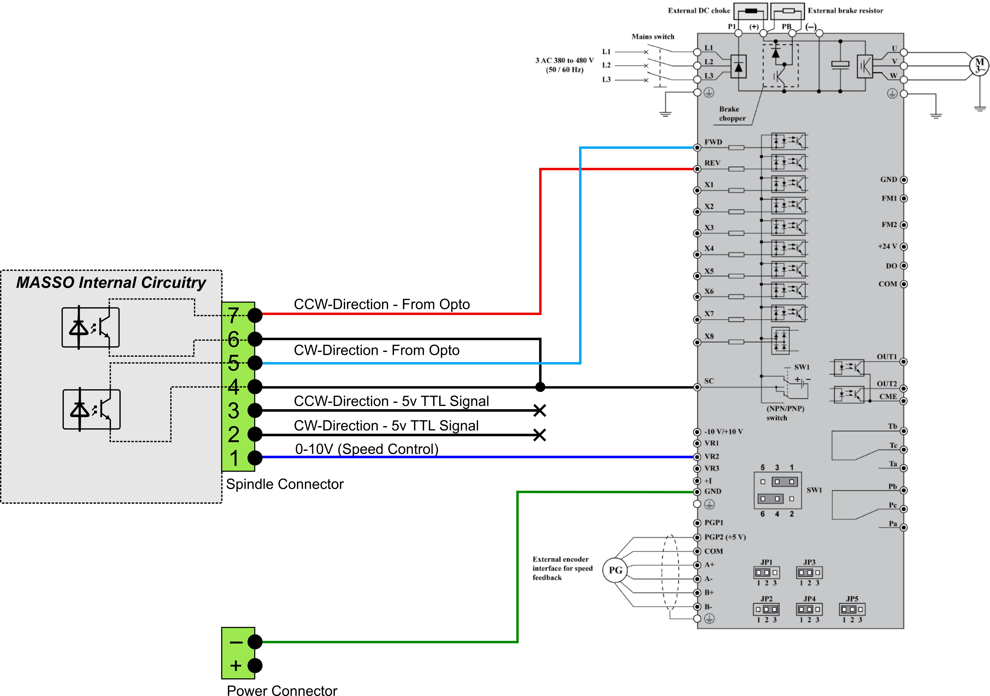
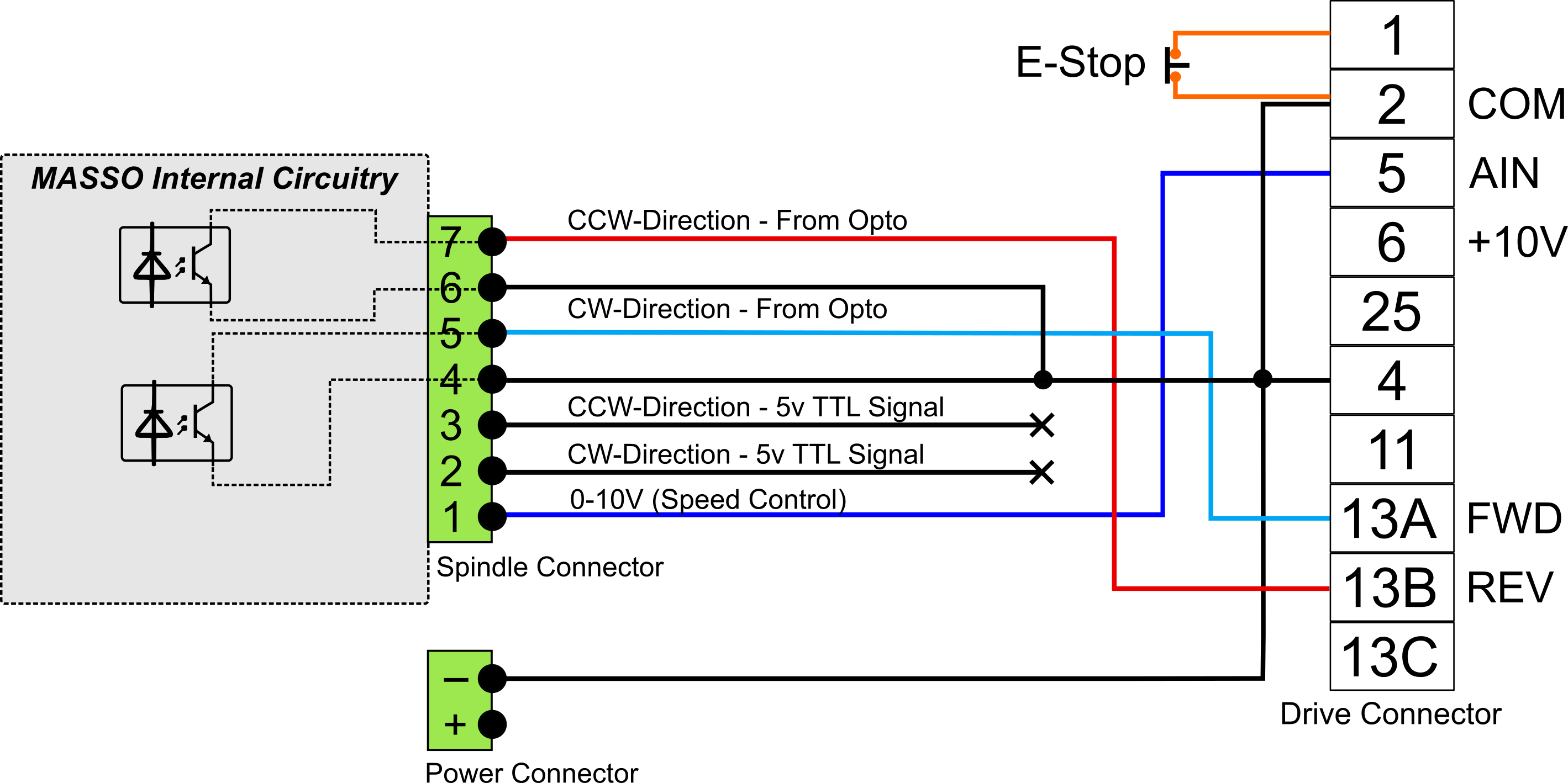
Understand vfd better by wiring the main circuit and control. Vfd motor control circuit diagram, related gallery: Like, subscribe and don�t skip the ads :)🔔 click the notification bell to get a notification about new videos !⚡🛠️ things you may need 🛠️⚡*****. 13.10.2018 13.10.2018 4 comments on altivar 61 control wiring diagram many parts in this variable speed drive, including printed wiring boards, operate at line voltage disconnect all power including external control power that may be present before altivar 61 drives up to ratings atv61hd15m3x, atv61hd18n4 and this function requires the use of. The software i use is uccnc (purchased together with uc300 motion controller), and spindle settings are:
![[DIAGRAM] Wiring Diagram Inverter Schneider FULL Version [DIAGRAM] Wiring Diagram Inverter Schneider FULL Version](https://www.mrodrives.com/images/xlarge/sgdv-5r5a11a-wiring-diagram.jpg) Source: anklediagrams.corrierte.it
Source: anklediagrams.corrierte.it
Vfd wiring diagram showing power in 1 vfd 2 motors variable frequency drive for constant. Using the variable frequency drive plc and hmi 7 of 32 21 setting device ip addresses in order for ccw on your pc to communicate with the vfd we first need to set up the ethernetip. The software i use is uccnc (purchased together with uc300 motion controller), and spindle settings are: Wiring diagram vfd with bypass starter. Thank you for clarification on that :) i have disconnected wire that goes from +12vout to vfd.
 Source: wiring89.blogspot.com
In two wire control there is no separate stop command is provided. These voltages must be electrically isolated from the standard 120 volts ac. Loss of control zthe designer of any wiring scheme must consider the potential failure modes of control channels and, for certain critical control functions, provide a means to achieve a safe state during and after a channel failure. 7 installing the drive controller mount the drive controller on a wall or the back of the enclosure according to the recommendations described in this document before installing the dc choke. Vfd is a short form of variable frequency drive or variable voltage variable frequency drive.the vfds are working based on changing the input frequency and input voltage of the motor, we can change.
 Source: pinterest.com
Phase 2 l1, l2, l3 ground, when used 7 installing the drive controller mount the drive controller on a wall or the back of the enclosure according to the recommendations described in this document before installing the dc choke. Difference between mcb and mccb miniature circuit breaker most. (4) multiple vfds ground should be connected to the earth respectively, do not make the ground wire form a loop. In two wire control there is no separate stop command is provided.
 Source: apiccolisogni.blogspot.com
Examples of critical control functions are emergency stop and overtravel stop. Learn the basic wiring of variable frequency drives / vfd with our electrician steve quist. 30% of nominal motor torque drive controllers ≤ atv31•u15••: Using the variable frequency drive plc and hmi 7 of 32 21 setting device ip addresses in order for ccw on your pc to communicate with the vfd we first need to set up the ethernetip. In this video, we used the very popular mitsubishi d700 series vfd, showing single phase and three phase wiring instructions.
 Source: wiringdiagram.2bitboer.com
Variable frequency drive for constant pressure water supply plc wiring vfd skills hands on electrical training zb 6184 abb control diagram free what is circuit its operation types and consulting specifying engineer web exclusive byp controlling 3 phase induction motor. 7 installing the drive controller mount the drive controller on a wall or the back of the enclosure according to the recommendations described in this document before installing the dc choke. I am here with giving you a vfd start stop wiring diagram for running a vfd through panel board push button and keypad of the vfd (it is called hmi). Vfd panel wiring diagram pdf wiring diagram line wiring diagram. We strongly recommend using a certified electrician.
 Source: wiringdiagramall.blogspot.com
Variable speed drives atv, atv installation manual. V remove the altivar from its packaging and check that it has not been damaged in transit. 50% of nominal motor torque drive controllers ≤ atv31•075••: These voltages must be electrically isolated from the standard 120 volts ac. Examples of critical control functions are emergency stop and overtravel stop.
 Source: masso.com.au
(4) multiple vfds ground should be connected to the earth respectively, do not make the ground wire form a loop. Like, subscribe and don�t skip the ads :)🔔 click the notification bell to get a notification about new videos !⚡🛠️ things you may need 🛠️⚡*****. In two wire control there is no separate stop command is provided. Two speeds one direction three phase motor connection power and control diagrams. The software i use is uccnc (purchased together with uc300 motion controller), and spindle settings are:
 Source: wiring.hpricorpcom.com
Learn the basic wiring of variable frequency drives / vfd with our electrician steve quist. (4) multiple vfds ground should be connected to the earth respectively, do not make the ground wire form a loop. Figure 6 shows the line and wiring schematics for this circuit. Browse altivar process in the schneider electric catalog including item #,voltage rating,enclosure rating,control voltage,digital inputs,analog inputs,analog outputs. Vfd start stop wiring diagram:
![[DIAGRAM] Wiring Diagram Inverter Schneider FULL Version [DIAGRAM] Wiring Diagram Inverter Schneider FULL Version](https://static-resources.imageservice.cloud/5173328/xantrex-xw-power-system-xantrex-xw-xantrex-xw-xantrex-xw-pdf.jpg) Source: anklediagrams.corrierte.it
Source: anklediagrams.corrierte.it
Vfd start stop wiring diagram: Browse altivar process in the schneider electric catalog including item #,voltage rating,enclosure rating,control voltage,digital inputs,analog inputs,analog outputs. Commissioning and parameters programming in vfd; Vfd wiring diagram showing power in 1 vfd 2 motors variable frequency drive for constant. We strongly recommend using a certified electrician.
Source: wiring89.blogspot.com
7 installing the drive controller mount the drive controller on a wall or the back of the enclosure according to the recommendations described in this document before installing the dc choke. 1 panel wiring vfd start stop wiring diagram. V remove the altivar from its packaging and check that it has not been damaged in transit. Using the variable frequency drive plc and hmi 7 of 32 21 setting device ip addresses in order for ccw on your pc to communicate with the vfd we first need to set up the ethernetip. Vfd is a short form of variable frequency drive or variable voltage variable frequency drive.the vfds are working based on changing the input frequency and input voltage of the motor, we can change.
 Source: rebablakuf.blogspot.com
7 installing the drive controller mount the drive controller on a wall or the back of the enclosure according to the recommendations described in this document before installing the dc choke. Specific wiring instructions for wall mounting drives. Phase 2 l1, l2, l3 ground, when used Thank you for clarification on that :) i have disconnected wire that goes from +12vout to vfd. Understand vfd better by wiring the main circuit and control.
This site is an open community for users to do sharing their favorite wallpapers on the internet, all images or pictures in this website are for personal wallpaper use only, it is stricly prohibited to use this wallpaper for commercial purposes, if you are the author and find this image is shared without your permission, please kindly raise a DMCA report to Us.
If you find this site serviceableness, please support us by sharing this posts to your own social media accounts like Facebook, Instagram and so on or you can also save this blog page with the title schneider vfd control wiring diagram by using Ctrl + D for devices a laptop with a Windows operating system or Command + D for laptops with an Apple operating system. If you use a smartphone, you can also use the drawer menu of the browser you are using. Whether it’s a Windows, Mac, iOS or Android operating system, you will still be able to bookmark this website.
Category
Related By Category
- Predator 670 engine wiring diagram Idea
- Frsky x8r wiring diagram information
- Pioneer ts wx130da wiring diagram Idea
- Johnson 50 hp wiring diagram Idea
- Kohler voltage regulator wiring diagram Idea
- Johnson 50 hp outboard wiring diagram information
- Kti hydraulic remote wiring diagram Idea
- Pyle plpw12d wiring diagram information
- Tx9600ts wiring diagram information
- Lifan 50cc wiring diagram information