Rv tv antenna booster wiring diagram information
Home » Trending » Rv tv antenna booster wiring diagram information
Your Rv tv antenna booster wiring diagram images are available. Rv tv antenna booster wiring diagram are a topic that is being searched for and liked by netizens today. You can Get the Rv tv antenna booster wiring diagram files here. Find and Download all free photos.
If you’re looking for rv tv antenna booster wiring diagram images information connected with to the rv tv antenna booster wiring diagram interest, you have pay a visit to the right site. Our website frequently provides you with suggestions for seeking the maximum quality video and image content, please kindly search and locate more enlightening video articles and graphics that match your interests.
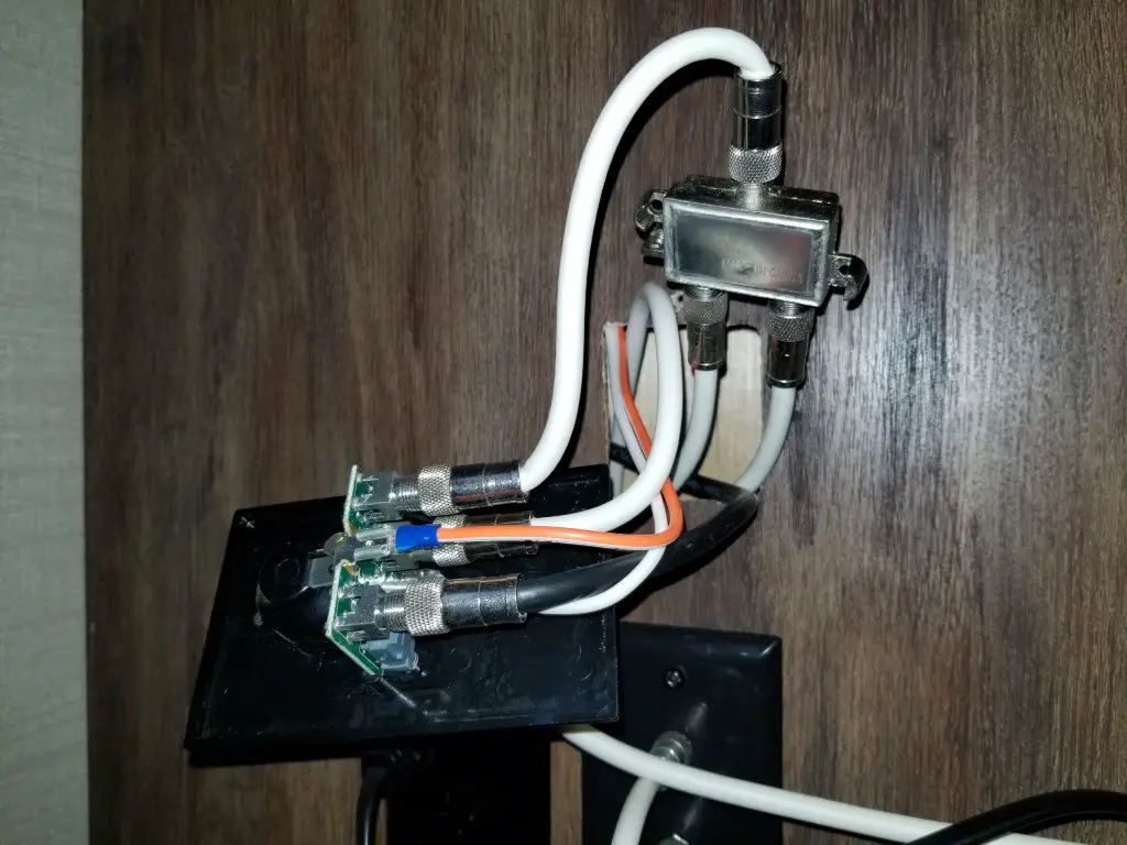
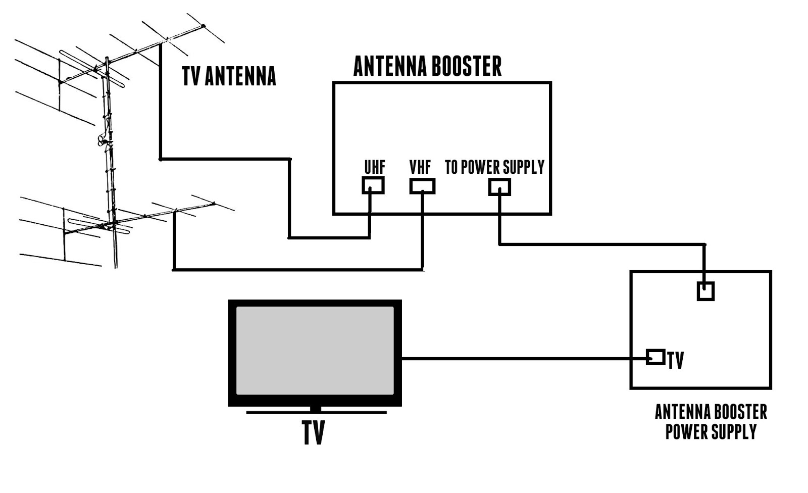
Rv Tv Antenna Booster Wiring Diagram. Each part should be set and linked to different parts in particular manner. Capacitors c2,c3 c4 ,c5 and inductors l3, l4 forms a uhf band pass filter. We bought the furrion access point and wifi booster to boost the wifi signal primarily. The wiring for your tvs comes in from a jack on the exterior, connects to the booster and then splits off to the other tv locations in the rv.
 Winegard Rv Antenna Wiring Diagram Wiring Diagram From wiringdiagram.2bitboer.com
The wire braiding is visible. When pushing the button on, the led flickers and goes out. It is best to find the fuse for that line and pull it before proceeding. Keystone rv cable tv wiring diagram. In fact almost all antenna tuner structures and principles are the same. The circuit shown here is of a tv antenna booster based on the transistor bf180.
Otherwise the arrangement will not function as it should be.
We bought the furrion access point and wifi booster to boost the wifi signal primarily. The circuit shown here is of a tv antenna booster based on the transistor bf180. The circuit operates in the uhf band and has a gain of 15db. I have the antenna booster with a button to amplify the rooftop antenna signal. The antenna booster is located in the keytv controller so owners always know where it is and don�t have to guess. Turn the tv antenna power booster located inside the unit to the off position in some units turn the booster to the cable position.
 Source: jaycoowners.com
The input signal is fed to the emitter of q1 through this filter. I�m trying to understand the cable/sat wiring. They look similar to figure 1 below and usually include a 12 volt outlet. Used 2009 keystone rv outback 230rs. Kz said, when using a portable sat to put the coax to the cable outlet, behind the tv attach the receiver�s coax in to the b outlet on the wall.
 Source: easywiring.info
The signal booster circuit was constructed on a line type vero board following the circuit diagram drawn. A wiring diagram is a streamlined traditional pictorial representation of an electrical circuit. Rv wifi & cell signal boosters. Capacitors c2,c3 c4 ,c5 and inductors l3, l4 forms a uhf band pass filter. Turn the wallplate switch (booster) on and verify the light is on.
 Source: weekendrvadventures.com
Winegard freevision sensar hv retrofit antenna kit. Use a good lap sealant recommended by your rv manufacturer for rubber or fiberglass. Home rv tv antenna booster wiring diagram. Rv tv antenna booster wiring diagram. There is a bathroom straight across from the door which provides a.
 Source: easywiring.info
Strip 1 2 inch of the outer protective plastic from the coaxial wire using wire strippers or a small knife. Use a good lap sealant recommended by your rv manufacturer for rubber or fiberglass. The wire braiding is visible. Aerials television antenna rotator wiring diagram cable png 1346x1056px area brand connecting an antenna or cable tv no box antennas direct digital tv. The wiring for your tvs comes in from a jack on the exterior, connects to the booster and then splits off to the other tv locations in the rv.
![[Download 22+] Jayco Tv Antenna Booster [Download 22+] Jayco Tv Antenna Booster](https://2020cadillac.com/wp-content/uploads/2019/02/rv-tv-cable-wiring-diagram-wiring-library-rv-cable-tv-wiring-diagram.jpg) Source: abclogic17.blogspot.com
Source: abclogic17.blogspot.com
This manual is focused on advanced beginners and intermediate users. Each part should be set and connected with different parts in specific manner. Mobile home breaker box diagram. Each part should be set and linked to different parts in particular manner. Newmar mountain aire and essex, cummins.

The circuit shown here is of a tv antenna booster based on the transistor bf180. I�m trying to understand the cable/sat wiring. The wiring for your tvs comes in from a jack on the exterior, connects to the booster and then splits off to the other tv locations in the rv. Turn the tv antenna power booster located inside the unit to the off position in some units turn the booster to the cable position. Newmar mountain aire and essex, cummins.
 Source: irv2.com
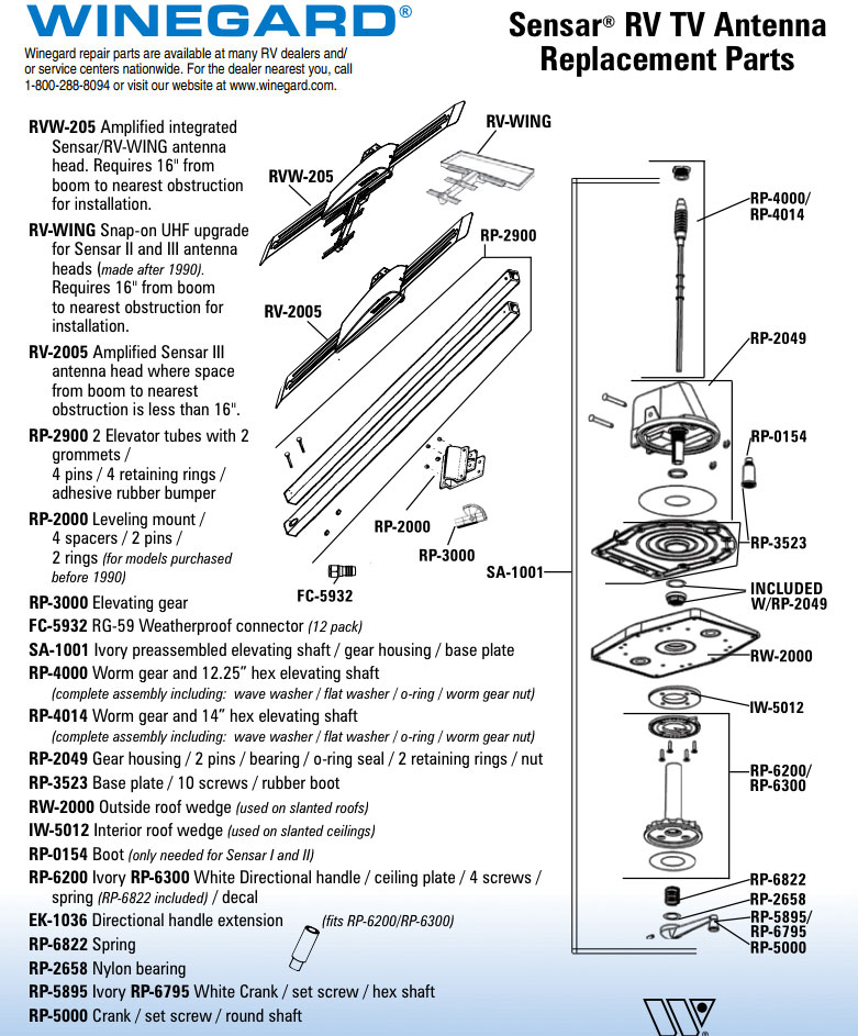
Rv antenna diagram rv antenna wiring diagram wiring diagram pertaining to winegard rv antenna parts diagram image size x px and to view image details please click the image. The wire braiding is visible. Keytv knows when the camper is hooked up to cable and automatically switches the. Winegard freevision sensar hv retrofit antenna kit. Posted by denny duplessis on 26th jan 2019.

Capacitors c2,c3 c4 ,c5 and inductors l3, l4 forms a uhf band pass filter. The wire braiding is visible. The circuit shown here is of a tv antenna booster based on the transistor bf180. Mobile home breaker box diagram. Rv antenna diagram rv antenna wiring diagram wiring diagram pertaining to winegard rv antenna parts diagram image size x px and to view image details please click the image.
 Source: wiringdiagram99.blogspot.com
91 93 1 4t60e ele04 702a wiring harness internal. Home rv tv antenna booster wiring diagram. The antenna booster is located in the keytv controller so owners always know where it is and don�t have to guess. Cable tv signal booster amplifier circuit diagram. The circuit shown here is of a tv antenna booster based on the transistor bf180.

We bought the furrion access point and wifi booster to boost the wifi signal primarily. Make sure that the tv is set to the correct channel per the instructions. Figure 3 below identifies each line. They look similar to figure 1 below and usually include a 12 volt outlet. Hook up the tv to the tv out jack on the receiver.
 Source: easywiring.info
Has on off switch indicator light set 2 output cable input and 12 vdc receptacle. We bought the furrion access point and wifi booster to boost the wifi signal primarily. The red wire is 12 volt +, the white wire is the neutral/ground. Has on off switch indicator light set 2 output cable input and 12 vdc receptacle. Keytv knows when the camper is hooked up to cable and automatically switches the.

Cable tv signal booster amplifier circuit diagram. This manual is focused on advanced beginners and intermediate users. Rv wifi & cell signal boosters. The circuit shown here is of a tv antenna booster based on the transistor bf180. The red wire is 12 volt +, the white wire is the neutral/ground.
 Source: circuitdiagramimages.blogspot.com
The antenna booster is located in the keytv controller so owners always know where it is and don�t have to guess. Capacitors c2,c3 c4 ,c5 and inductors l3, l4 forms a uhf band pass filter. Aerials television antenna rotator wiring diagram cable png 1346x1056px area brand connecting an antenna or cable tv no box antennas direct digital tv. The wire braiding is visible. Each part should be set and connected with different parts in specific manner.

Rv antenna diagram rv antenna wiring diagram • wiring diagram pertaining to winegard rv antenna parts diagram, image size x px, and to view image details please click the image. Rv wifi & cell signal boosters. In fact almost all antenna tuner structures and principles are the same. There is a bathroom straight across from the door which provides a. Turn the tv antenna power booster located inside the unit to the off position in some units turn the booster to the cable position.
 Source: forestriverforums.com
Figure 3 below identifies each line. They look similar to figure 1 below and usually include a 12 volt outlet. Enter the underlined 5 digit code to verify you are not a robot: Hook up the tv to the tv out jack on the receiver. Rv antenna diagram rv antenna wiring diagram wiring diagram pertaining to winegard rv antenna parts diagram image size x px and to view image details please click the image.

Strip 1 2 inch of the outer protective plastic from the coaxial wire using wire strippers or a small knife. Rv antenna diagram rv antenna wiring diagram • wiring diagram pertaining to winegard rv antenna parts diagram, image size x px, and to view image details please click the image. They look similar to figure 1 below and usually include a 12 volt outlet. Otherwise, the arrangement will not function as it should be. The wiring for your tvs comes in from a jack on the exterior, connects to the booster and then splits off to the other tv locations in the rv.
 Source: 16.seo-memo.de
Keytv knows when the camper is hooked up to cable and automatically switches the. Keytv knows when the camper is hooked up to cable and automatically switches the. Rv wifi & cell signal boosters. Showing that power is connected to the antenna and thetv sets are receiving signals from the antenna. There will be main lines that are represented by l1 l2 l3 and so on.
 Source: rv52.com
Has on off switch indicator light set 2 output cable input and 12 vdc receptacle. Newmar mountain aire and essex, cummins. This manual is focused on advanced beginners and intermediate users. Wall platepower supply provides 12 vdc to antenna as well as antenna signals to two tv sets. Here is a picture gallery about winegard rv antenna parts diagram complete with the description of the image, please find the image you need.
This site is an open community for users to share their favorite wallpapers on the internet, all images or pictures in this website are for personal wallpaper use only, it is stricly prohibited to use this wallpaper for commercial purposes, if you are the author and find this image is shared without your permission, please kindly raise a DMCA report to Us.
If you find this site value, please support us by sharing this posts to your preference social media accounts like Facebook, Instagram and so on or you can also save this blog page with the title rv tv antenna booster wiring diagram by using Ctrl + D for devices a laptop with a Windows operating system or Command + D for laptops with an Apple operating system. If you use a smartphone, you can also use the drawer menu of the browser you are using. Whether it’s a Windows, Mac, iOS or Android operating system, you will still be able to bookmark this website.
Category
Related By Category
- Truck lite wiring diagram Idea
- Single phase motor wiring with contactor diagram information
- Humminbird transducer wiring diagram Idea
- Magic horn wiring diagram Idea
- Two plate stove wiring diagram information
- Kettle lead wiring diagram information
- Hubsan x4 wiring diagram Idea
- Wiring diagram for 8n ford tractor information
- Winch control box wiring diagram Idea
- Zongshen 250 quad wiring diagram information