Rv transfer switch wiring diagram Idea
Home » Trend » Rv transfer switch wiring diagram Idea
Your Rv transfer switch wiring diagram images are ready. Rv transfer switch wiring diagram are a topic that is being searched for and liked by netizens today. You can Find and Download the Rv transfer switch wiring diagram files here. Find and Download all royalty-free photos and vectors.
If you’re looking for rv transfer switch wiring diagram pictures information related to the rv transfer switch wiring diagram interest, you have visit the ideal site. Our site frequently provides you with hints for seeing the maximum quality video and picture content, please kindly hunt and find more informative video articles and images that match your interests.
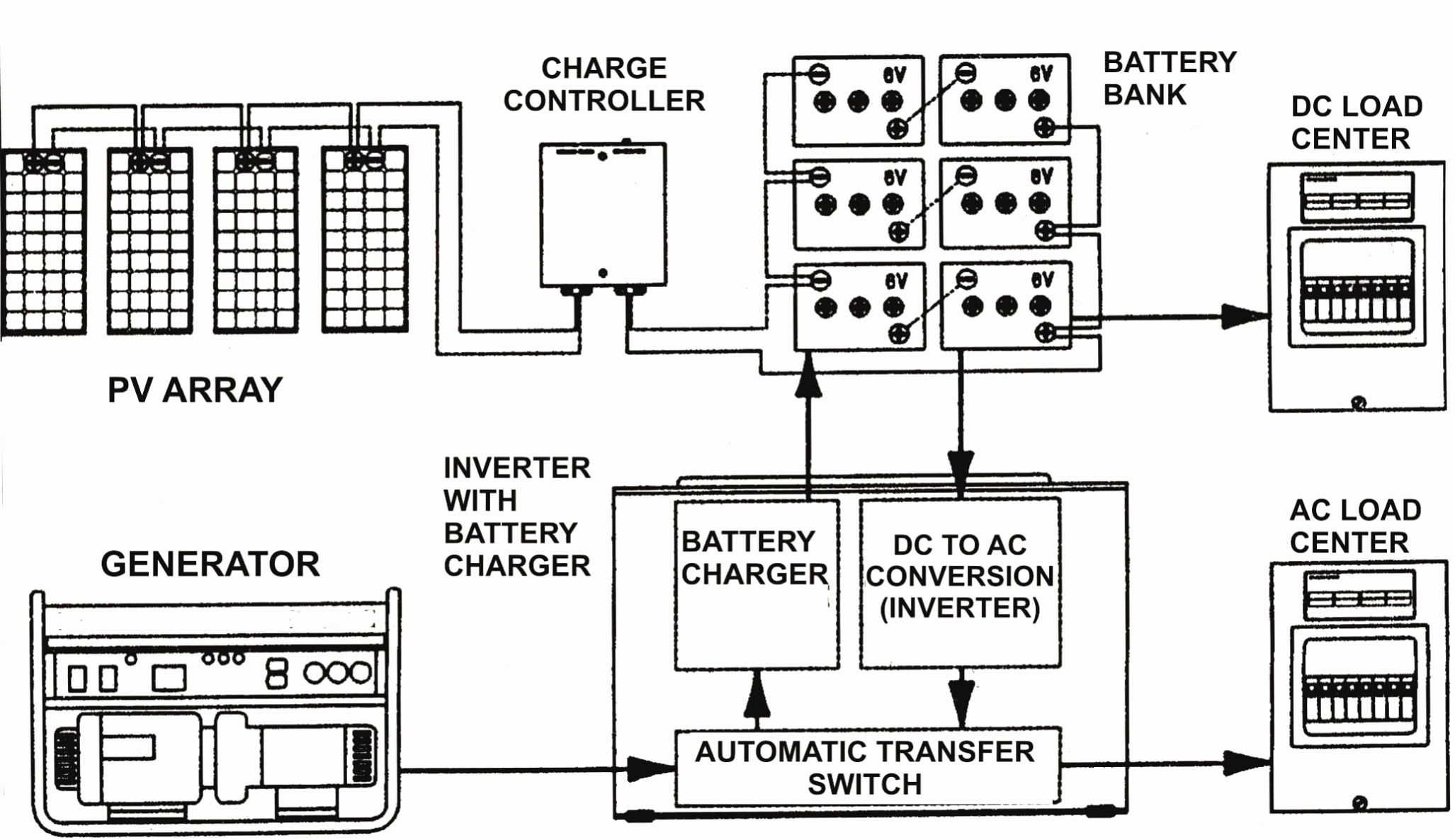
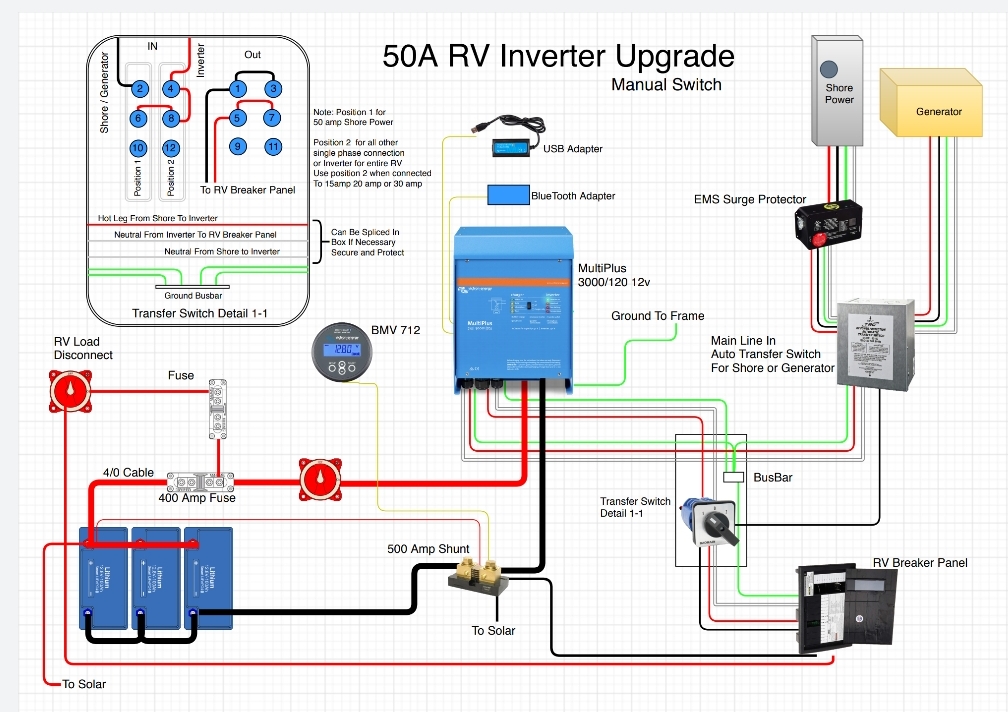
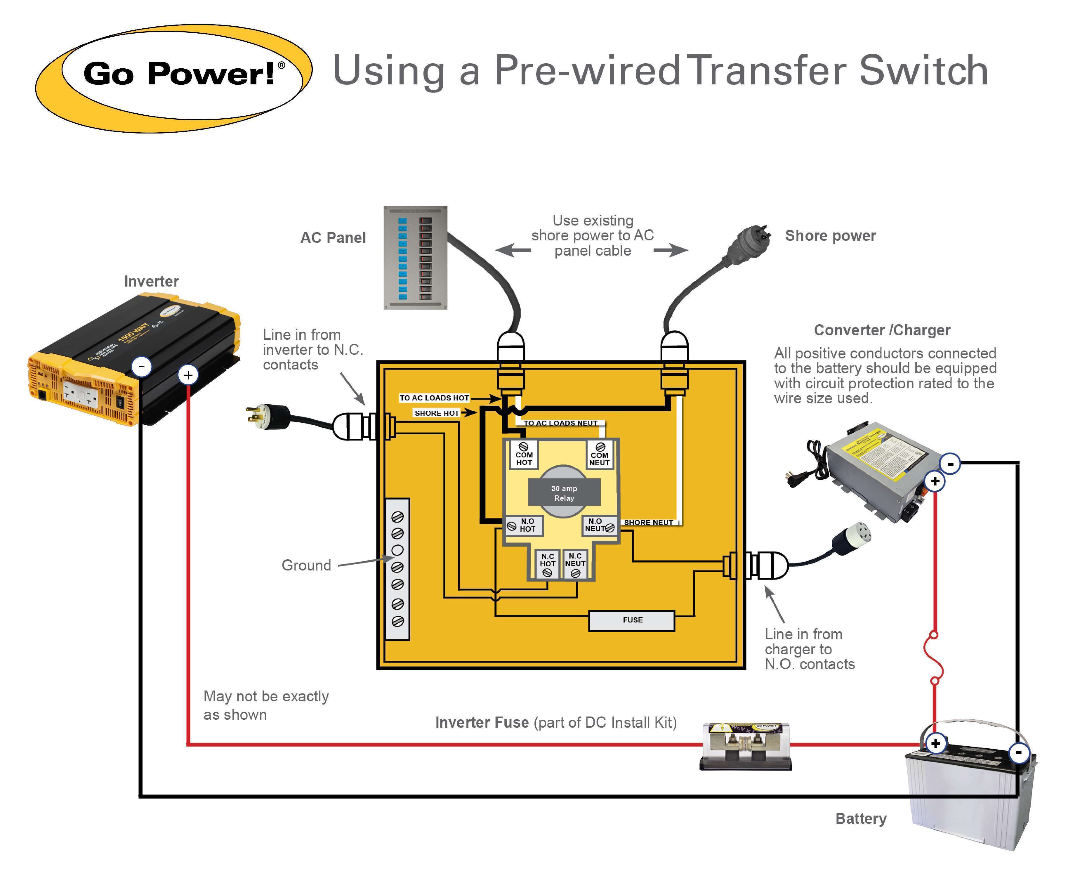
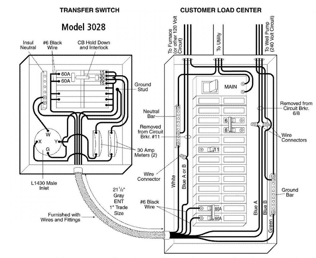
Rv Transfer Switch Wiring Diagram. Some also have ems under/over voltage protection. Consult the manufacturer’s wiring diagram, which is usually fixed to the inside of the transfer box case, for. It really is supposed to aid all the average person in creating a proper program. Injunction of 2 wires is generally indicated by black dot to the junction of 2 lines.
 50 Amp Rv Transfer Switch Wiring Diagram Wiring Diagram From wiringdiagram.2bitboer.com
Consult the rv manufacturer’s literature to determine which color coded wires serve which purpose, and consult. Consult the manufacturer’s wiring diagram, which is usually fixed to the inside of the transfer box case, for. Each component should be set and linked to other parts in specific manner. As you know, some devices require ac and some require dc. These instructions will probably be easy to understand and apply. Automatic transfer switch 50a hardwire model transfers to generator power automatically when energized after 30 second delay (generator mode).
Wiring diagram for a 50 amp 240 volt circuit breaker electrical circuit diagram electrical wiring diagram electrical wiring.
Before installing a rv transfer switch you will want to make sure that all power sources to the rv are disconnected, including generators, shore lines and batteries. This article describes how to install a 30 amp shore power system on a small boat. These directions will likely be easy to comprehend and implement. There are three poles on most transfer switches. When you make use of your finger or perhaps the actual circuit with your eyes, it is easy to mistrace the circuit. It is intended to assist all of the typical user in creating a correct system.
Source: ekerekizul.blogspot.com
They come in two sizes: 30 amp rv transfer switch wiring diagram 30 amp rv transfer switch wiring diagram you looking for are usable for you here. 50 amp rv transfer switch wiring diagram. You can click on products to learn more. A wiring diagram is a simple visual representation from the physical connections and physical layout of the electrical system or circuit.
 Source: ricardolevinsmorales.com
Provided that there is a sufficient source of electricity, converters and inverters give an rv the flexibility to power all of its devices regardless of the power source, ac or dc. 1 trick that we 2 to printing a similar wiring plan off twice. Collection of rv automatic transfer switch wiring diagram. Yes (automatically bypass inverter when plugged into shore) 120v ac distribution panel: Its three prong receptacle visually defines this socket type.
 Source: rvtravel.com
Wiring diagram comes with numerous easy to adhere to wiring diagram instructions. Consult the rv manufacturer’s literature to determine which color coded wires serve which purpose, and consult. There will be main lines that are represented by l1, l2, l3, and so on. As you know, some devices require ac and some require dc. The wires should be drawn through 1 of 3 knockouts located on the underside of the switch.
 Source: prdprc.udtrucks.com
Such as png, jpg, animated gifs, pic art, logo, black and white,. Wiring diagram comes with numerous easy to adhere to wiring diagram instructions. In this article, we also have variety of photos usable. The ground wire will be green or bare copper. 1 trick that we 2 to printing a similar wiring plan off twice.
 Source: kelvin-okl.blogspot.com
When you make use of your finger or perhaps the actual circuit with your eyes, it is easy to mistrace the circuit. Before installing a rv transfer switch you will want to make sure that all power sources to the rv are disconnected, including generators, shore lines and batteries. Automatic transfer switch 50a hardwire model transfers to generator power automatically when energized after 30 second delay (generator mode). How to wire a transfer switch for an rv step 1. Ask the experts a question >>.
 Source: annawiringdiagram.com
Wiring diagram for 30 amp automatic transfer switch for power inverter installs. I also attached a second picture that shows what�s underneath the lid. Yes (each load is protected by an appropriate breaker) As you know, some devices require ac and some require dc. Injunction of 2 wires is generally indicated by black dot to the junction of 2 lines.
 Source: kelvin-okl.blogspot.com
120240 vac 60 hz input. This article describes how to install a 30 amp shore power system on a small boat. When you make use of your finger or perhaps the actual circuit with your eyes, it is easy to mistrace the circuit. Wiring diagram comes with numerous easy to adhere to wiring diagram instructions. Wiring diagram for 30 amp automatic transfer switch for power inverter installs.
 Source: gpelectric.com
Injunction of 2 wires is generally indicated by black dot to the junction of 2 lines. Shore power plug wiring diagram. Consult the manufacturer’s wiring diagram, which is usually fixed to the inside of the transfer box case, for. Wiring diagram for a 50 amp 240 volt circuit breaker electrical circuit diagram electrical wiring diagram electrical wiring. On the top panel of the furrion transfer switch # f50ats is a diagram that shows how it will wire to your weekend warrior.
 Source: kovodym.blogspot.com
Wiring diagram for 30 amp automatic transfer switch for power inverter installs. It really is supposed to aid all the average person in creating a proper program. Wiring diagram comes with numerous easy to adhere to wiring diagram instructions. Wiring diagrams help technicians to view what sort of controls are wired to the system. The automatic rv transfer switch has decals where everything gets hooked up.
 Source: ricardolevinsmorales.com
This article describes how to install a 30 amp shore power system on a small boat. 1 trick that we 2 to printing a similar wiring plan off twice. Each component should be set and linked to other parts in specific manner. Wiring diagram for a 50 amp 240 volt circuit breaker electrical circuit diagram electrical wiring diagram electrical wiring. There are three poles on most transfer switches.
 Source: ekerekizul.blogspot.com
Such as png, jpg, animated gifs, pic art, logo, black and white,. The wires should be drawn through 1 of 3 knockouts located on the underside of the switch. You�ll find the white neutral wire as well as a blasck l1 wire and red l2 wire. Remove the 4×4 boxes and disconnect any wires that are connected to the older style units. In this article, we also have variety of photos usable.
 Source: rv.net
It really is supposed to aid all the average person in creating a proper program. The ground wire will be green or bare copper. Each component should be set and linked to other parts in specific manner. There will be main lines that are represented by l1, l2, l3, and so on. You can see examples of this by directing your attention to the rv electrical diagram at the top of the page.
 Source: wiringdiagram.2bitboer.com
There will be main lines that are represented by l1, l2, l3, and so on. The wires should be drawn through 1 of 3 knockouts located on the underside of the switch. A wiring diagram is a simple visual representation from the physical connections and physical layout of the electrical system or circuit. Here is an interactive version of our wiring diagram for camper van, skoolie, rv, etc. These directions will likely be easy to comprehend and implement.
 Source: eduhubgeek.blogspot.com
Consult the rv manufacturer’s literature to determine which color coded wires serve which purpose, and consult. Wiring diagram for 30 amp automatic transfer switch for power inverter installs. Consult the rv manufacturer’s literature to determine which color coded wires serve which purpose, and consult. It really is supposed to aid all the average person in creating a proper program. When you make use of your finger or perhaps the actual circuit with your eyes, it is easy to mistrace the circuit.
Source: kelvin-okl.blogspot.com
Generally the circuit breaker for the rv shore power is located at the pedestal you plug into. Shore power plug wiring diagram. When you make use of your finger or perhaps the actual circuit with your eyes, it is easy to mistrace the circuit. These instructions will probably be easy to understand and apply. You can see examples of this by directing your attention to the rv electrical diagram at the top of the page.
 Source: outsidesupply.com
It really is supposed to aid all the average person in creating a proper program. The shore power cord has a male plug on both ends. You�ll find the white neutral wire as well as a blasck l1 wire and red l2 wire. Wiring diagram for 30 amp automatic transfer switch for power inverter installs. Wiring diagram for a 50 amp 240 volt circuit breaker electrical circuit diagram electrical wiring diagram electrical wiring.
 Source: dentistmitcham.com
These directions will likely be easy to comprehend and implement. A wiring diagram is a simple visual representation from the physical connections and physical layout of the electrical system or circuit. Consult the manufacturer’s wiring diagram, which is usually fixed to the inside of the transfer box case, for. As stated previous, the lines at a rv transfer switch wiring diagram represents wires. I also attached a second picture that shows what�s underneath the lid.
 Source: faceitsalon.com
As stated previous, the lines at a rv transfer switch wiring diagram represents wires. I also attached a second picture that shows what�s underneath the lid. You can click on products to learn more. The typical components in a wiring diagram are ground power supply wire and link output devices switches resistors reasoning gate lights and so on. In this article, we also have variety of photos usable.
This site is an open community for users to do submittion their favorite wallpapers on the internet, all images or pictures in this website are for personal wallpaper use only, it is stricly prohibited to use this wallpaper for commercial purposes, if you are the author and find this image is shared without your permission, please kindly raise a DMCA report to Us.
If you find this site convienient, please support us by sharing this posts to your own social media accounts like Facebook, Instagram and so on or you can also bookmark this blog page with the title rv transfer switch wiring diagram by using Ctrl + D for devices a laptop with a Windows operating system or Command + D for laptops with an Apple operating system. If you use a smartphone, you can also use the drawer menu of the browser you are using. Whether it’s a Windows, Mac, iOS or Android operating system, you will still be able to bookmark this website.
Category
Related By Category
- Predator 670 engine wiring diagram Idea
- Frsky x8r wiring diagram information
- Pioneer ts wx130da wiring diagram Idea
- Johnson 50 hp wiring diagram Idea
- Kohler voltage regulator wiring diagram Idea
- Johnson 50 hp outboard wiring diagram information
- Kti hydraulic remote wiring diagram Idea
- Pyle plpw12d wiring diagram information
- Tx9600ts wiring diagram information
- Lifan 50cc wiring diagram information