Rv holding tank sensor wiring diagram Idea
Home » Trend » Rv holding tank sensor wiring diagram Idea
Your Rv holding tank sensor wiring diagram images are ready in this website. Rv holding tank sensor wiring diagram are a topic that is being searched for and liked by netizens now. You can Get the Rv holding tank sensor wiring diagram files here. Find and Download all free photos.
If you’re looking for rv holding tank sensor wiring diagram images information connected with to the rv holding tank sensor wiring diagram topic, you have pay a visit to the right site. Our website frequently provides you with suggestions for downloading the highest quality video and picture content, please kindly hunt and locate more informative video content and images that fit your interests.
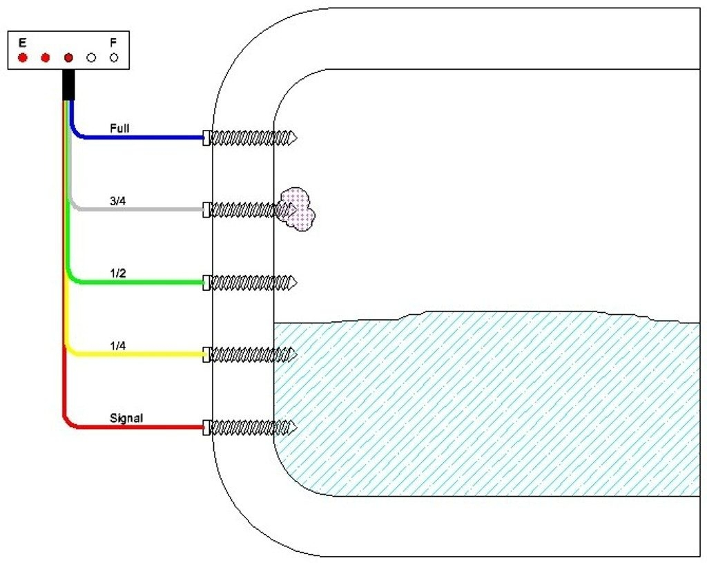
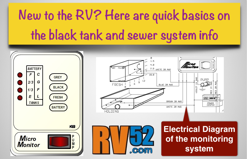
Rv Holding Tank Sensor Wiring Diagram. Each sensor is wired to a light on a monitor, and each of those lights signifies a separate fill percentage: All panels also have a lighted switch to control the water pump. Rv holding tank sensor wiring diagram. This little black cylinder is about three inches long, about 3/8 inch in diameter, and is wire tied to the top of the holding tank.
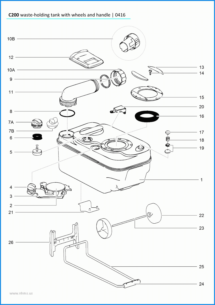 Rv Holding Tank Sensor Wiring Rv Circuit Diagrams Simple From 2020cadillac.com
Diagnosis guide for the kib monitor system no lights on panel when switch is pushed. All of it depends on circuit that is being built. Wiring diagram comes with numerous easy to adhere to wiring diagram instructions. They are mounted through the sidewall of a holding tank so that each sensor’s head is on the inside of the tank and the sensors physically ascend or descend in a line on the body of the holding tank. The rv holding tank are the storage tanks on your rv that hold the used shower and sink water as well as waste from the restroom. That will become a matter of personal preference.
A traditional tank sensor completes the circuit in a simple low voltage electrical system.
The following is based on an above ground pump and single phase motor and a basic mechanical pressure switch. By vallery masson on february 22, 2021. All panels also have a lighted switch to control the water pump. Some people do not allow solid waste on their rv and insist that a bag be used and then discarded. But, it does not mean connection between the wires. For convenience, a second display console can be added to the system by.
 Source: pinterest.com
That is, the full sensor wiring from the black, grey and fresh water tanks is connected to the f led on the monitor panel. I decide to start with wiring up the control display panel first before venturing underneath the rig to attach the four tank sensor strips. They are connected to the square plastic block by white wires. These guidelines will likely be easy to grasp and apply. For convenience, a second display console can be added to the system by.
 Source: easywiring.info
The following is based on an above ground pump and single phase motor and a basic mechanical pressure switch. The following is based on an above ground pump and single phase motor and a basic mechanical pressure switch. Fresh, grey, and black tank levels. It is supposed to help each of the average person in creating a correct method. I decide to start with wiring up the control display panel first before venturing underneath the rig to attach the four tank sensor strips.
 Source: circuit-plan.blogspot.com
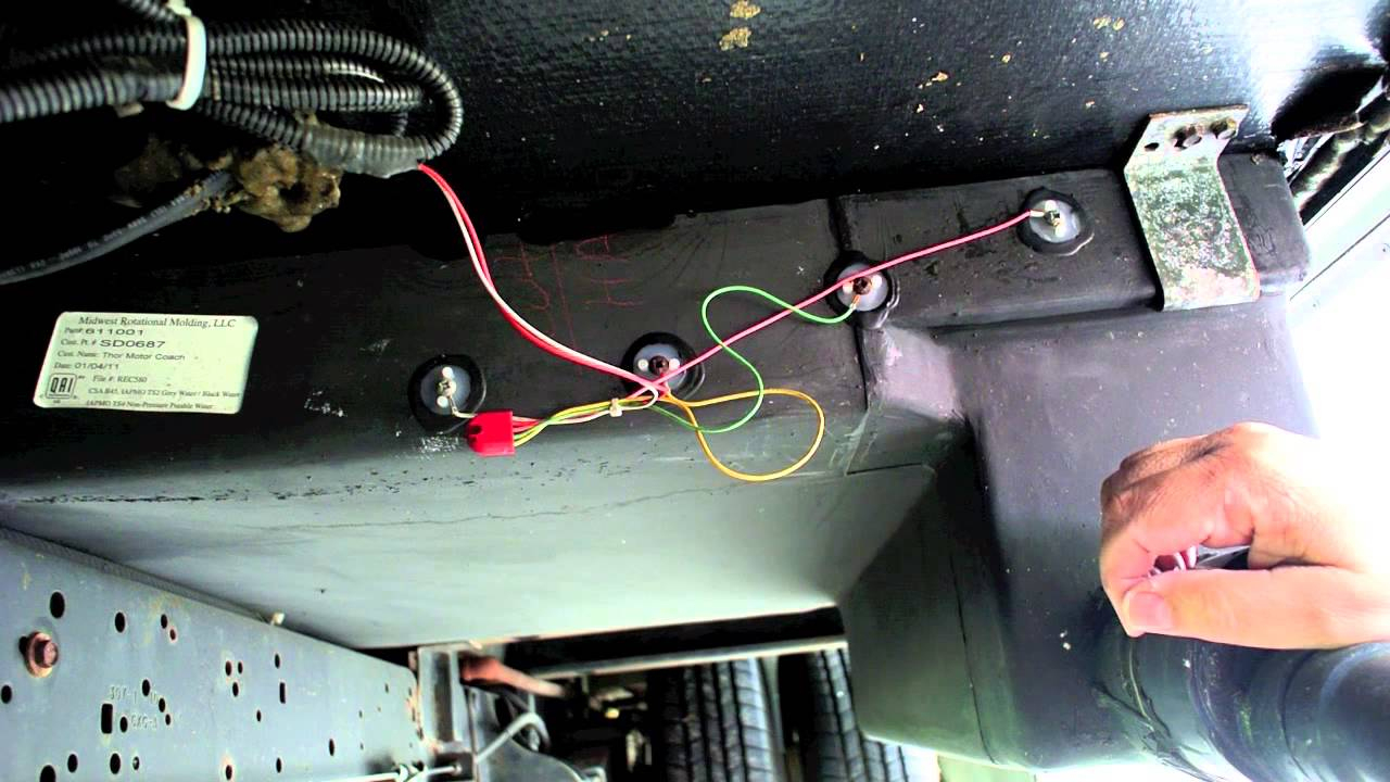
There will be a white wire that goes to frame ground and is even with the bottom probe and is not part of the resistor pack. System includes (1) display monitor, (3) tank senders, and (1) pigtail. They are mounted through the sidewall of a holding tank so that each sensor’s head is on the inside of the tank and the sensors physically ascend or descend in a line on the body of the holding tank. One at a time should show which wire should connect to which probe. All panels also have a lighted switch to control the water pump.
 Source: 2020cadillac.com
These guidelines will likely be easy to grasp and apply. Fresh, grey, and black tank levels. Each sensor is wired to a light on a monitor, and each of those lights signifies a separate fill percentage: As you can see the 1/4 light will be lit as soon as the tank is. According to the wiring diagram for my coach the f wiring is red, the 3/4 wiring is orange.
 Source: easywiring.info
If not the arrangement will not work as it ought to be. How do holding tank sensors for rvs work? Visit howstuffworks to check out this brake light wiring diagram. All panels also have a lighted switch to control the water pump. Stereo wiring harness for rv wiring diagram rv tank sensor wiring diagram wiring schematic diagram dtc 5043d column load cell da8c9 kib tank sensor wiring harness digital resources rv monitor panel overview rv repair club rv tank sensor wiring diagram wiring schematic.
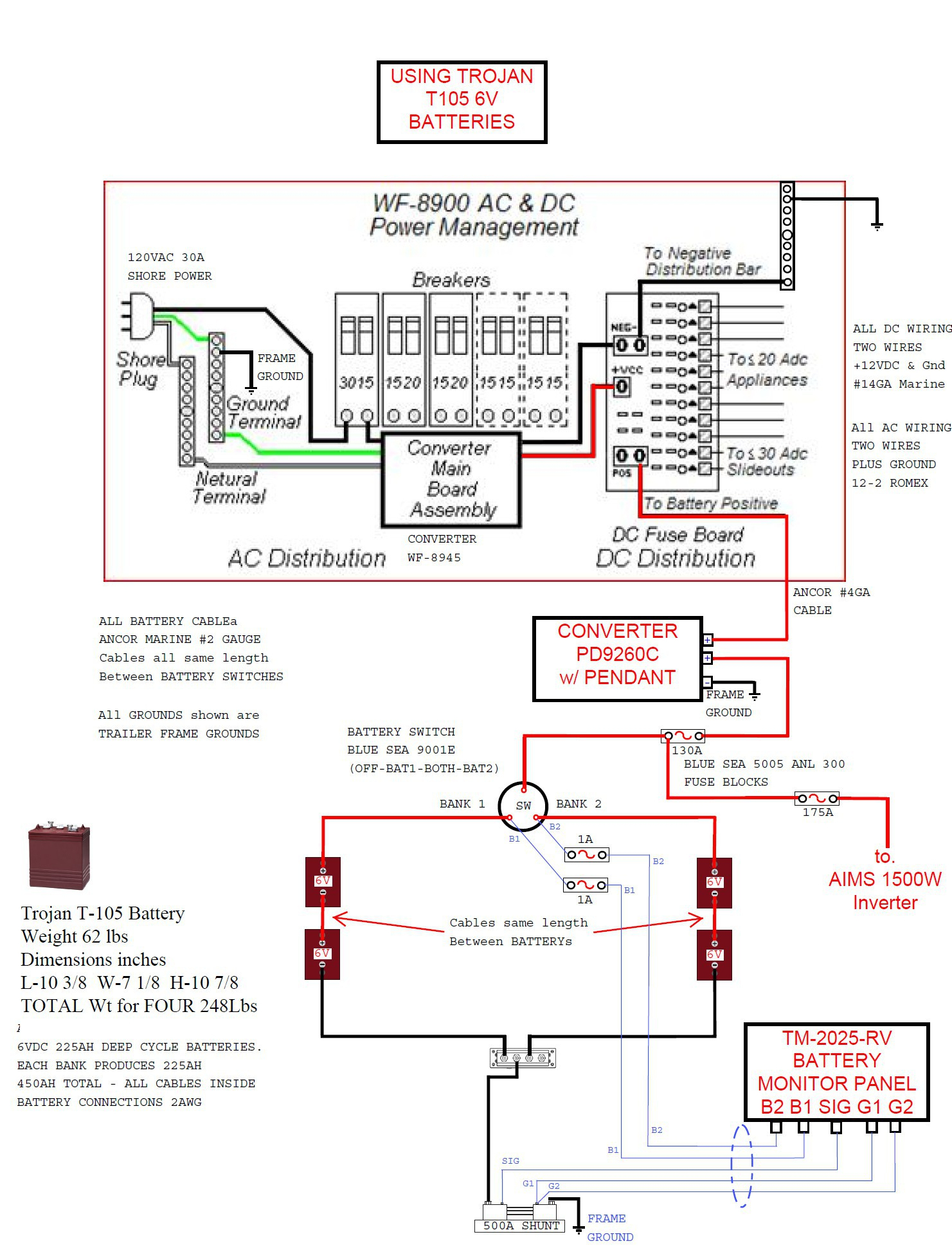 Source: annawiringdiagram.com
A circuit was established between the monitor and your tank probes through the water or sludge. It is supposed to help each of the average person in creating a correct method. These guidelines will likely be easy to grasp and apply. The following is based on an above ground pump and single phase motor and a basic mechanical pressure switch. They are mounted through the sidewall of a holding tank so that each sensor’s head is on the inside of the tank and the sensors physically ascend or descend in a line on the body of the holding tank.
 Source: 2020cadillac.com
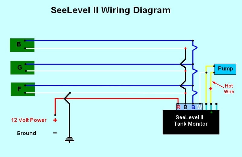
This engine wiring diagram can be used to install engine performance part of your car. The following is based on an above ground pump and single phase motor and a basic mechanical pressure switch. Once you have placed your sensors (according to the provided diagram) connect the wire extension to one of the three connectors on the split pigtail, corresponding to the tank you are measuring (grey wire goes to grey water tank, brown wire goes to black water tank, and blue water goes to fresh water tank). There will be a white wire that goes to frame ground and is even with the bottom probe and is not part of the resistor pack. Wiring diagram comes with numerous easy to adhere to wiring diagram instructions.
 Source: openrangeowners.com
It is supposed to help each of the average person in creating a correct method. Kib tank sensor wiring diagram. How do holding tank sensors for rvs work? All panels also have a lighted switch to control the water pump. This engine wiring diagram can be used to install engine performance part of your car.
 Source: 2020cadillac.com
A traditional tank sensor completes the circuit in a simple low voltage electrical system. Sensors may be permanent or removable. A traditional tank sensor completes the circuit in a simple low voltage electrical system. It shows the components of the circuit as simplified shapes, and the aptitude and signal connections surrounded by the devices. The rv holding tank are the storage tanks on your rv that hold the used shower and sink water as well as waste from the restroom.
 Source: easywiring.info
Failed rv holding tank sensors how to test and replace For convenience, a second display console can be added to the system by. This very critical in single wire systems. Access to or knowledge of the wiring diagram are the cornerstones of the suburban water heater has a fast recovery time and fewer cool water cycles. There will be a white wire that goes to frame ground and is even with the bottom probe and is not part of the resistor pack.
 Source: annawiringdiagram.com
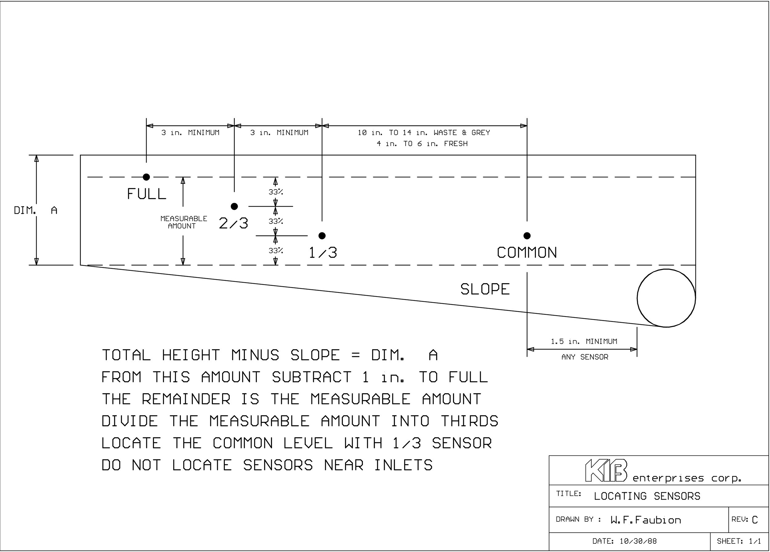
All 3 tanks are wired the same. For convenience, a second display console can be added to the system by. Wiring diagram comes with numerous easy to adhere to wiring diagram instructions. The number 1 sensor is placed in the middle of the tank. All the sensor wires attach to this thing, with one wire coming out of it that goes to the circuit board on the tank indicator panel.
 Source: mainetreasurechest.com
The empty light is always hot and never goes out. Kib tank sensor wiring diagram : Look at the gray or fresh water tank. A wiring diagram is a streamlined conventional pictorial representation of an electric. This little black cylinder is about three inches long, about 3/8 inch in diameter, and is wire tied to the top of the holding tank.
 Source: rv52.com
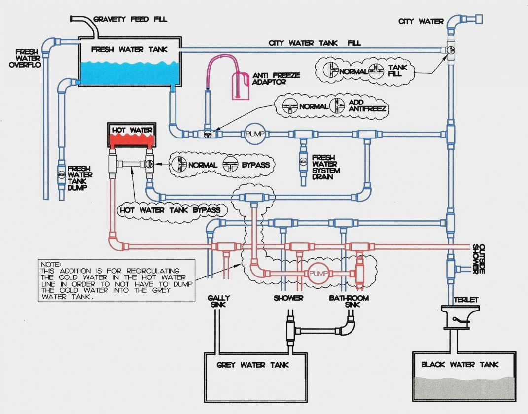
The rv holding tank are the storage tanks on your rv that hold the used shower and sink water as well as waste from the restroom. Once you install the new resisitor which has either 4 or 5 wires. Diagnosis guide for the kib monitor system no lights on panel when switch is pushed. All 3 tanks are wired the same. Once you have placed your sensors (according to the provided diagram) connect the wire extension to one of the three connectors on the split pigtail, corresponding to the tank you are measuring (grey wire goes to grey water tank, brown wire goes to black water tank, and blue water goes to fresh water tank).
![[MK_0960] Rv Holding Tank Sensor Wiring Wiring Diagram [MK_0960] Rv Holding Tank Sensor Wiring Wiring Diagram](https://static-cdn.imageservice.cloud/2703555/kib-m1379-micro-monitor-notes-forest-river-forums.jpg) Source: dogan.phae.mohammedshrine.org
Source: dogan.phae.mohammedshrine.org
Injunction of two wires is usually indicated by black dot in the intersection of 2 lines. As you can see the 1/4 light will be lit as soon as the tank is. There will be a white wire that goes to frame ground and is even with the bottom probe and is not part of the resistor pack. They suggested that a jumper wire be used to check the lights. A good ground connection to the vehicle frame, connected to the individual colored wires.
 Source: motorhome.com
Here are photos of the tank sensors. A traditional tank sensor completes the circuit in a simple low voltage electrical system. The rv holding tank are the storage tanks on your rv that hold the used shower and sink water as well as waste from the restroom. Kib tank sensor wiring diagram : Rv holding tank sensor wiring diagram.
 Source: loveyourrv.com
The sensors stick on the side of the tank. They suggested that a jumper wire be used to check the lights. Here are photos of the tank sensors. How do holding tank sensors for rvs work? It is supposed to help each of the average person in creating a correct method.
 Source: annawiringdiagram.com
Sensors may be permanent or removable. According to previous, the traces in a rv holding tank sensor wiring diagram signifies wires. Each sensor is wired to a light on a monitor, and each of those lights signifies a separate fill percentage: The following is based on an above ground pump and single phase motor and a basic mechanical pressure switch. Holding tank monitoring system wiring diagram.
 Source: mainetreasurechest.com
If not the arrangement will not work as it ought to be. Fresh, grey, and black tank levels. All of it depends on circuit that is being built. Visit howstuffworks to check out this brake light wiring diagram. Sometimes, the wires will cross.
This site is an open community for users to do submittion their favorite wallpapers on the internet, all images or pictures in this website are for personal wallpaper use only, it is stricly prohibited to use this wallpaper for commercial purposes, if you are the author and find this image is shared without your permission, please kindly raise a DMCA report to Us.
If you find this site helpful, please support us by sharing this posts to your preference social media accounts like Facebook, Instagram and so on or you can also bookmark this blog page with the title rv holding tank sensor wiring diagram by using Ctrl + D for devices a laptop with a Windows operating system or Command + D for laptops with an Apple operating system. If you use a smartphone, you can also use the drawer menu of the browser you are using. Whether it’s a Windows, Mac, iOS or Android operating system, you will still be able to bookmark this website.
Category
Related By Category
- Predator 670 engine wiring diagram Idea
- Frsky x8r wiring diagram information
- Pioneer ts wx130da wiring diagram Idea
- Johnson 50 hp wiring diagram Idea
- Kohler voltage regulator wiring diagram Idea
- Johnson 50 hp outboard wiring diagram information
- Kti hydraulic remote wiring diagram Idea
- Pyle plpw12d wiring diagram information
- Tx9600ts wiring diagram information
- Lifan 50cc wiring diagram information