Rs485 to ethernet wiring diagram Idea
Home » Trend » Rs485 to ethernet wiring diagram Idea
Your Rs485 to ethernet wiring diagram images are ready in this website. Rs485 to ethernet wiring diagram are a topic that is being searched for and liked by netizens now. You can Find and Download the Rs485 to ethernet wiring diagram files here. Download all free photos.
If you’re looking for rs485 to ethernet wiring diagram images information connected with to the rs485 to ethernet wiring diagram interest, you have pay a visit to the right blog. Our site frequently gives you suggestions for seeking the highest quality video and picture content, please kindly hunt and locate more enlightening video articles and images that match your interests.
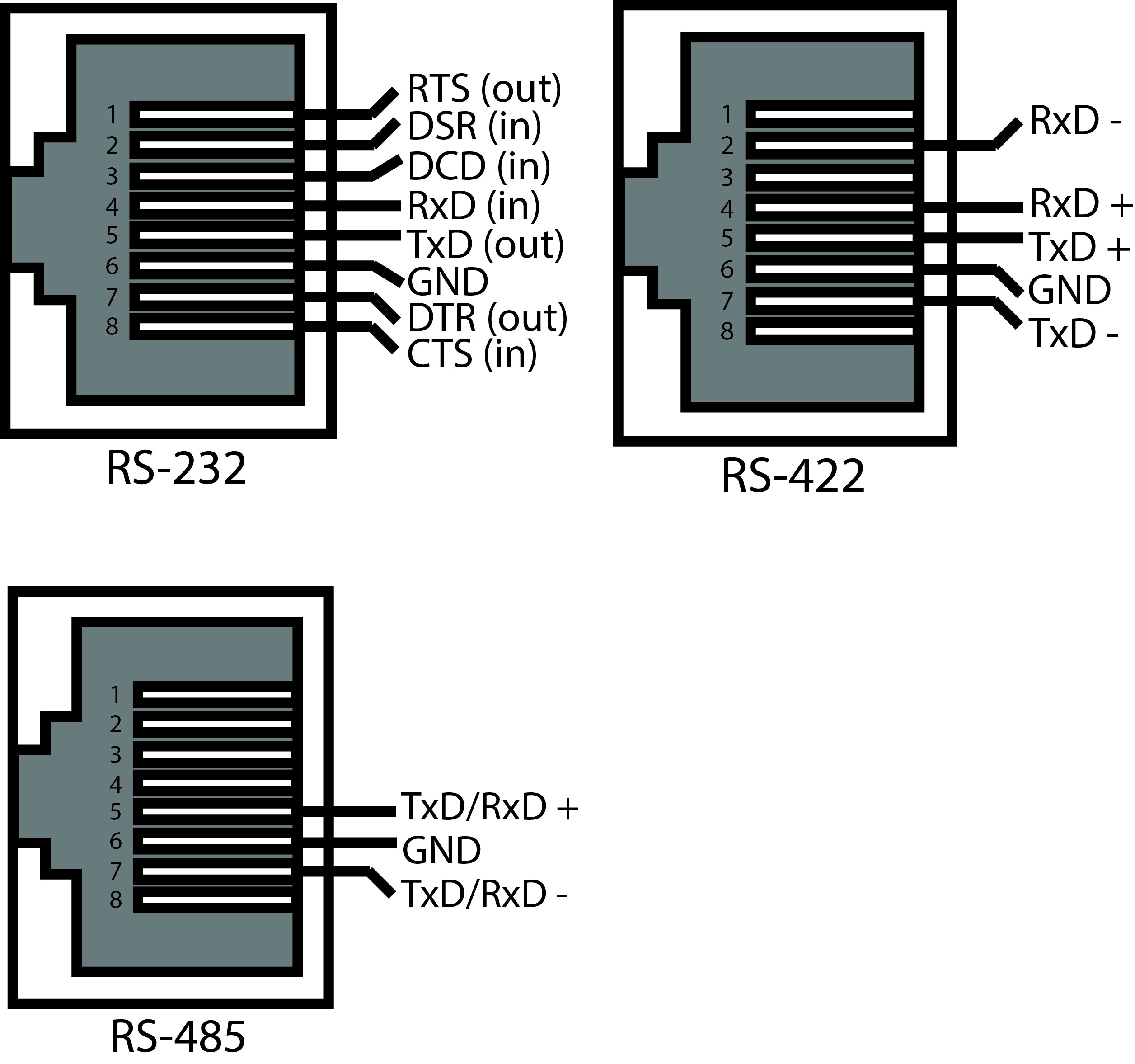
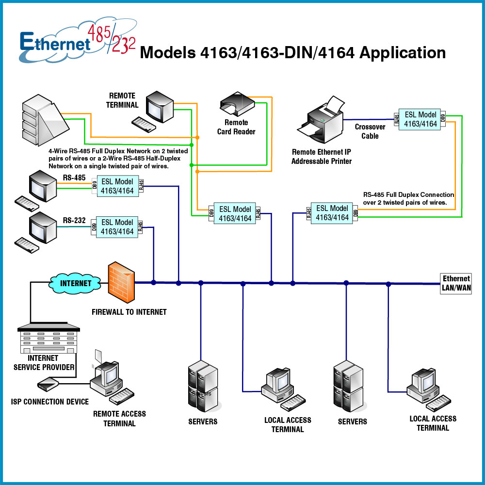
Rs485 To Ethernet Wiring Diagram. Pin 1 ← white and green wire → pin 3; Cat5 is slow and outdated, and rarely used anymore. Ace rs232 ports have three pin connectors. Rs485multiple driver communications rs485 is similar to rs422 upon which it is based.
 Rs485 To Rj45 Wiring Diagram New Charming, Null Modem From tonetastic.info
Occasionally, the cables will cross. The problem in point of fact is that all car is different. Shows how to properly wire the ig21 to a third party device over rs485 connection. Trim off any nylon strands or wire guides. It is recommended that the ground wire be connected to all stations to provide a common return. Rj45 connectors pin # signal name description 1 not used 2 not used 3 +tr + data line required for rs485 communication.
Rs 485 wiring diagram wiring diagram is a simplified enjoyable pictorial representation of an electrical circuit.
Rs485 to rj45 wiring diagram view and download allen bradley powerflex 4 user manual online adjustable frequency ac drive powerflex 4 controller pdf manual download, n t 8 0 9 0 4 2 0 1 5 5 a e d p a g 3 4 linterfaccia if2e011 in grado in modalit bridge di There will be primary lines that are represented by l1, l2, l3, and so on. Type of cable to use. Figure 4 is a pin diagram for both 25 pin rs485 pinout half duplex and full duplex pinout connectors. Each pair consists of a solid. Cat5 is slow and outdated, and rarely used anymore.
 Source: detoxicrecenze.com
Rs 485 wiring diagram wiring diagram is a simplified enjoyable pictorial representation of an electrical circuit. Rs232 rs422 rs485 standard db connector pinout opengear help desk connector network engineer standard. Rj45 connectors pin # signal name description 1 not used 2 not used 3 +tr + data line required for rs485 communication. Ace rs232 ports have three pin connectors. Pin 4 ← blue wire → pin 4;
 Source: usbwiringdiagram.com
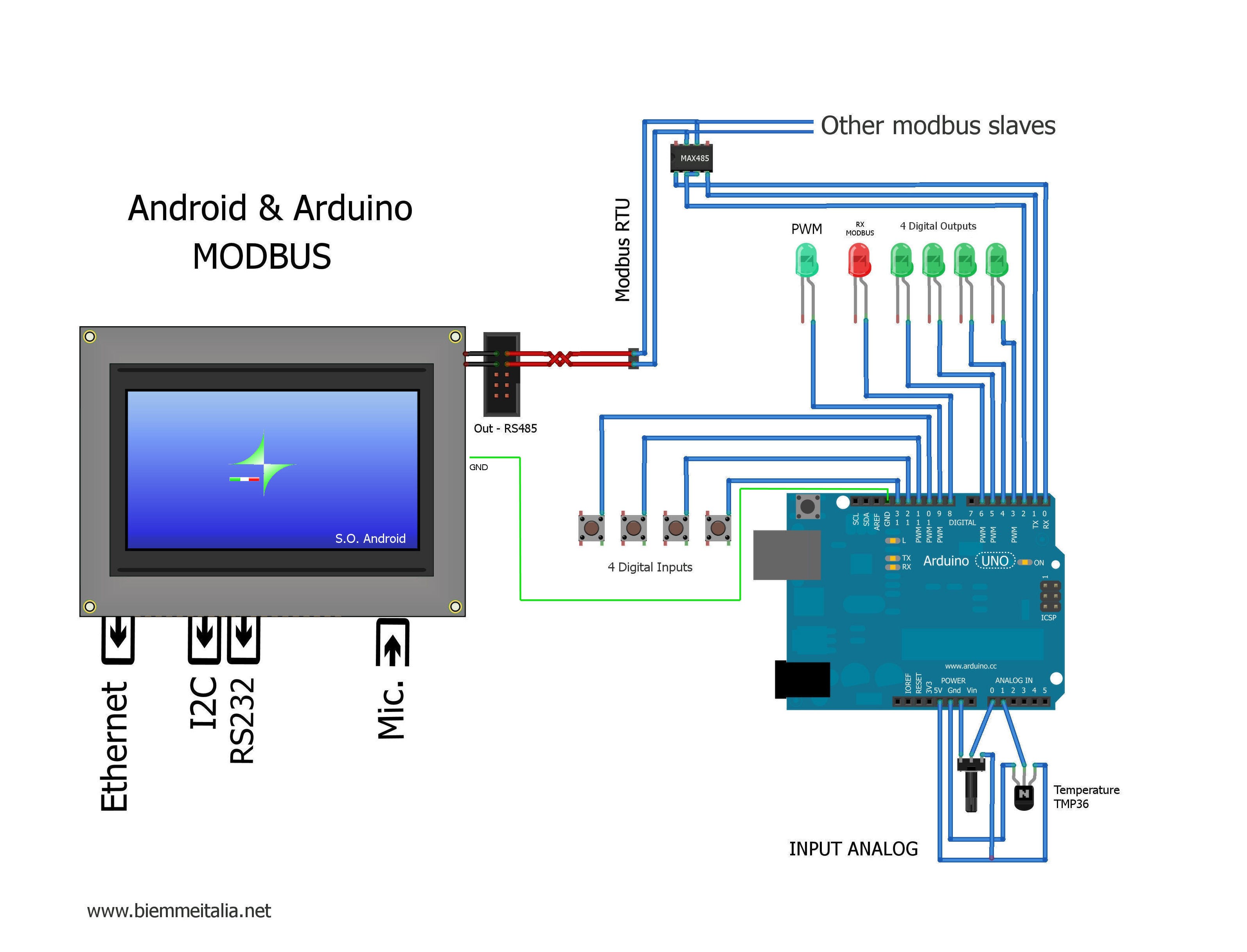
Cable trunk is commonly terminated with Figure 3 is an rs485 wiring diagram for rs485 pinout db9 connectors. Rs232 to rs485 cable pinout diagram module electronics lab com converter and adapter wiki how make a port check electronic template networking rut manual or proteus rs422 db9 db25 serial e sch rs 232 485 modbus star c3 wiring diagnosis main interface advantech converting signaling connections faq 2 wire pcb board for mb car datasheet psm. Rs485 (2) wiring type] to 1: Shows how to properly wire the ig21 to a third party device over rs485 connection.
 Source: detoxicrecenze.com
5 not used 6 rtn signal return common reference for logical signals. Rs485 wiring diagram the diagram below: Take off pin8 and pin9 connection, to choose rs232 channel, take off rs485 channel g t connection method 1: Pin 8 brown wire pin 8. The rs232 of pins de is mc power supply.
 Source: mikroelectron.com
Figure 4 is a pin diagram for both 25 pin rs485 pinout half duplex and full duplex pinout connectors. Pin 2 ← green wire → pin 6; Shows how to properly wire the ig21 to a third party device over rs485 connection. Pin 8 brown wire pin 8. Rj45 pinout diagram shows wiring for standard t568b t568a and crossover cable.
 Source: pinterest.com
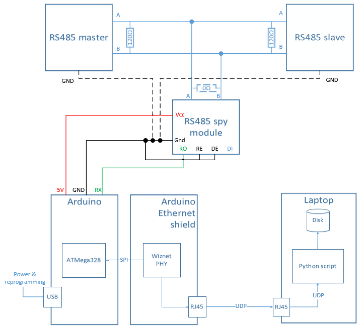
Pin 8 ← brown wire → pin 8; Shows how to properly wire the ig21 to a third party device over rs485 connection. Injunction of 2 wires is generally indicated by black dot to the intersection of 2 lines. Tia 568a diagram enthusiast wiring diagrams u2022 rh rasalibre co cat 5. Only the master is physically connected to the internet through the ethernet port.
 Source: tonetastic.info
Cable trunk is commonly terminated with Gone exasperating to remove, replace or repair the wiring in an automobile, having an accurate and detailed coolster mountopz 125cc. Only the master is physically connected to the internet through the ethernet port. Rs232 rs422 rs485 standard db connector pinout opengear help desk connector network engineer standard. Refer to the diagrams below for connection details.
 Source: aliexpress.com
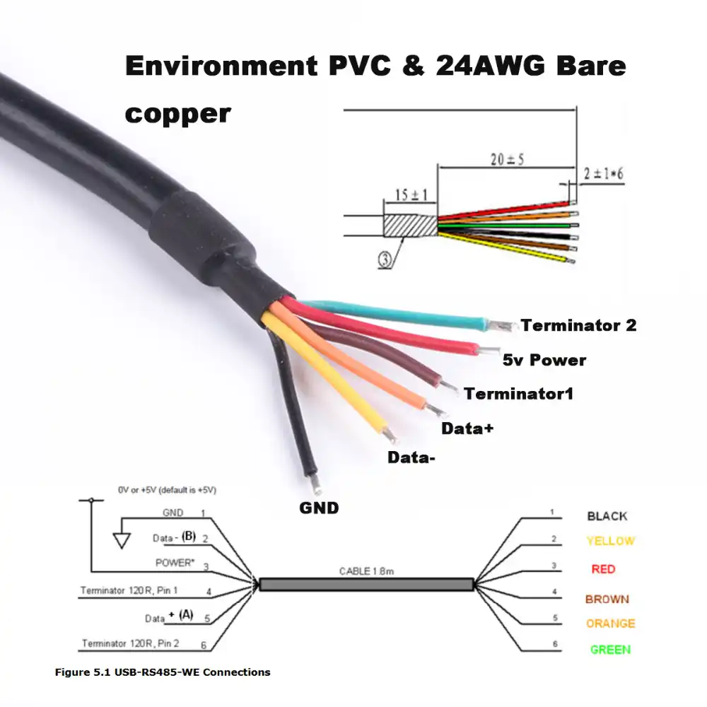
Pin 2 ← green wire → pin 6; Terminating resistors (rt) are connected across the ends of the a b wires. Pin 8 ← brown wire → pin 8; Gone exasperating to remove, replace or repair the wiring in an automobile, having an accurate and detailed coolster mountopz 125cc. Cat5 is slow and outdated, and rarely used anymore.
 Source: tonetastic.info
Ace rs232 ports have three pin connectors. The diagram below shows the general wiring layout for a net2 plus acu. Rs485 to rj45 wiring diagram view and download allen bradley powerflex 4 user manual online adjustable frequency ac drive powerflex 4 controller pdf manual download, n t 8 0 9 0 4 2 0 1 5 5 a e d p a g 3 4 linterfaccia if2e011 in grado in modalit bridge di Cat5 is slow and outdated, and rarely used anymore. The problem in point of fact is that all car is different.
 Source: wiringdiagramall.blogspot.com
5 not used 6 rtn signal return common reference for logical signals. Pin 5 ← white and blue wire → pin 5; Single phase energy hub inverter with prism technology. Solaredge wiring diagram wiring diagram is a simplified okay pictorial representation of an electrical circuit. 5 not used 6 rtn signal return common reference for logical signals.
 Source: untpikapps.com
It is not a ttl level (0 / 5 vdc) : Refer to the diagrams below for connection details. Each device has the ability to turn off its output drivers, so only the one device that is linking to the host outputs a signal on its tx lines. Multiple devices, rs485 bus, wired ethernet (lan) connection figure 8: The problem in point of fact is that all car is different.
 Source: shahyawala.blogspot.com
The problem in point of fact is that all car is different. Each device has the ability to turn off its output drivers, so only the one device that is linking to the host outputs a signal on its tx lines. Single phase energy hub inverter with prism technology. Multiple devices, rs485 bus, wired ethernet (lan) connection figure 8: Pin 2 ← green wire → pin 6;
 Source: pinterest.com
For rs 422 485 connect pins 5 to 20 and 7 to 22. Pin 4 ← blue wire → pin 4; Rs485 (2) wiring type] to 1: Dtech dt 9026 active rs232 to rs485 rs422 converter ethernet serial. 5 not used 6 rtn signal return common reference for logical signals.
 Source: shahyawala.blogspot.com
Our serial port is a true standard rs232/485. Rs485 (2) wiring type] to 1: Tia 568a diagram enthusiast wiring diagrams u2022 rh rasalibre co cat 5. Cat5 is slow and outdated, and rarely used anymore. Pin 5 ← white and blue wire → pin 5;
 Source: shahyawala.blogspot.com
Cable trunk is commonly terminated with Rs485 wiring diagram the diagram below: Rj45 pinout diagram shows wiring for standard t568b t568a and crossover cable. Each pair consists of a solid. Refer to the diagrams below for connection details.
 Source: tonetastic.info
Pin 8 brown wire pin 8. Wiring diagram rs 485 422 pinout png 800x714px area black and white brand doent. Our serial port is a true standard rs232/485. Solaredge wiring diagram wiring diagram is a simplified okay pictorial representation of an electrical circuit. Ace rs232 ports have three pin connectors.
 Source: sitzone.blogspot.com
The rs232 of pins de is mc power supply. The problem in point of fact is that all car is different. You can take a look at the security camera wire diagram below before. Only the master is physically connected to the internet through the ethernet port. Type of cable to use.
![[KLGH_4419] Rs 232 Db9 Wire Diagram Database Wire Diagram [KLGH_4419] Rs 232 Db9 Wire Diagram Database Wire Diagram](https://c.76.my/Malaysia/cisco-rs232-db9-female-serial-to-rj45-ethernet-adapter-console-cable-doinfinity-1707-08-doinfinity@2.jpg) Source: riannaa.produktutveckling.nu
Source: riannaa.produktutveckling.nu
Rs485/rs422 end transmission distance is 1200 meters, ethernet port transmission distance is 100 meters. Figure 3 is an rs485 wiring diagram for rs485 pinout db9 connectors. Pin 8 brown wire pin 8. Rs485 wiring diagram the diagram below: Rs232 rs422 rs485 standard db connector pinout opengear help desk connector network engineer standard.
 Source: tonetastic.info
Figure 3 is an rs485 wiring diagram for rs485 pinout db9 connectors. Rs485/rs422 end transmission distance is 1200 meters, ethernet port transmission distance is 100 meters. Rs485 wiring diagram the diagram below: The cable to be used is a shielded twisted pair telephone type. If you run a cat 5/6 ethernet cable of your security camera,.
This site is an open community for users to share their favorite wallpapers on the internet, all images or pictures in this website are for personal wallpaper use only, it is stricly prohibited to use this wallpaper for commercial purposes, if you are the author and find this image is shared without your permission, please kindly raise a DMCA report to Us.
If you find this site serviceableness, please support us by sharing this posts to your preference social media accounts like Facebook, Instagram and so on or you can also bookmark this blog page with the title rs485 to ethernet wiring diagram by using Ctrl + D for devices a laptop with a Windows operating system or Command + D for laptops with an Apple operating system. If you use a smartphone, you can also use the drawer menu of the browser you are using. Whether it’s a Windows, Mac, iOS or Android operating system, you will still be able to bookmark this website.
Category
Related By Category
- Predator 670 engine wiring diagram Idea
- Frsky x8r wiring diagram information
- Pioneer ts wx130da wiring diagram Idea
- Johnson 50 hp wiring diagram Idea
- Kohler voltage regulator wiring diagram Idea
- Johnson 50 hp outboard wiring diagram information
- Kti hydraulic remote wiring diagram Idea
- Pyle plpw12d wiring diagram information
- Tx9600ts wiring diagram information
- Lifan 50cc wiring diagram information