Rs232 to rj45 wiring diagram Idea
Home » Trending » Rs232 to rj45 wiring diagram Idea
Your Rs232 to rj45 wiring diagram images are available in this site. Rs232 to rj45 wiring diagram are a topic that is being searched for and liked by netizens now. You can Get the Rs232 to rj45 wiring diagram files here. Get all free vectors.
If you’re looking for rs232 to rj45 wiring diagram images information connected with to the rs232 to rj45 wiring diagram topic, you have pay a visit to the right blog. Our website frequently provides you with suggestions for seeking the maximum quality video and picture content, please kindly search and find more enlightening video content and images that fit your interests.
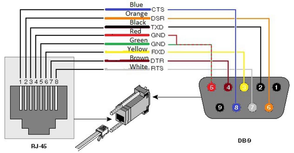
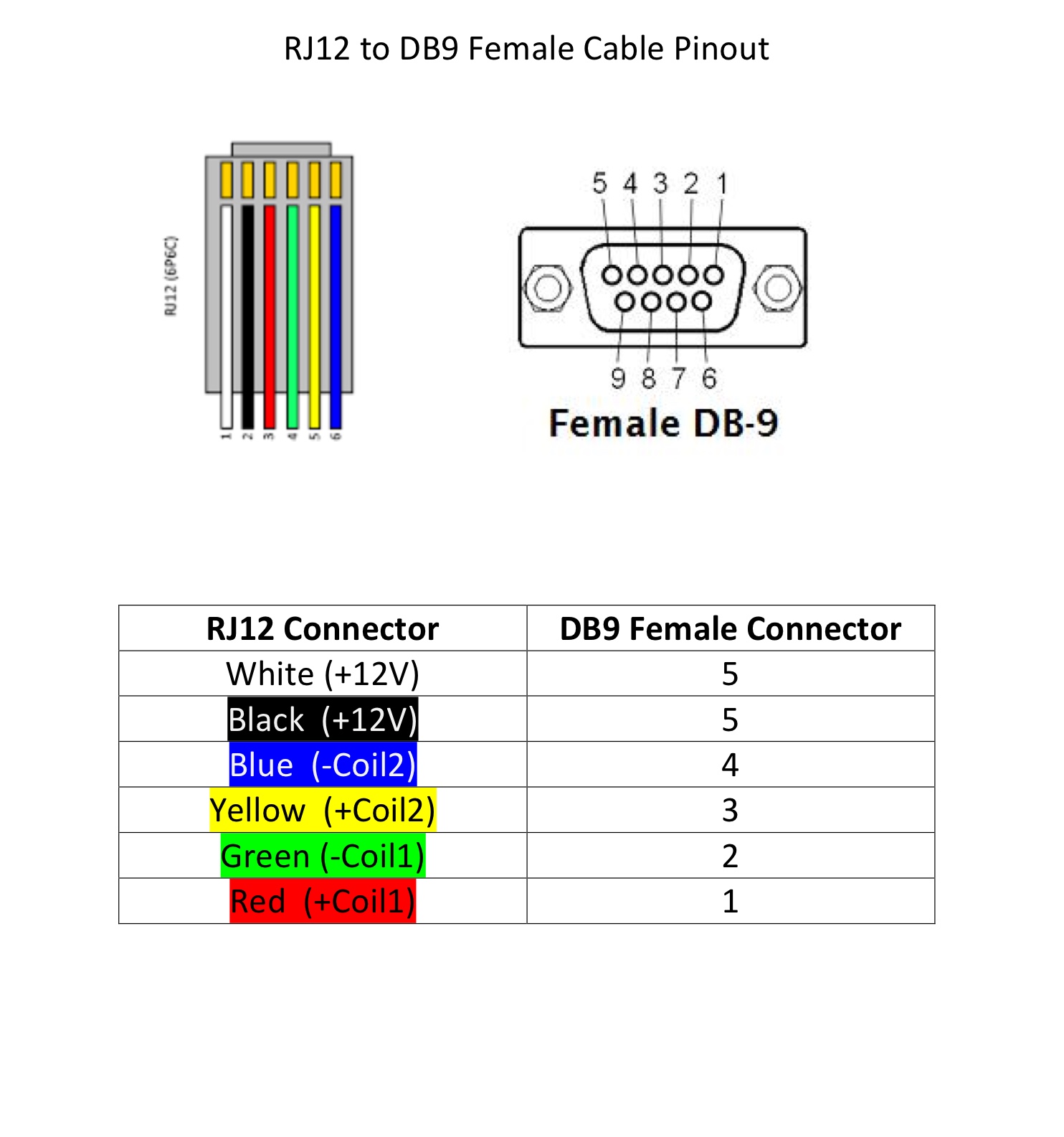
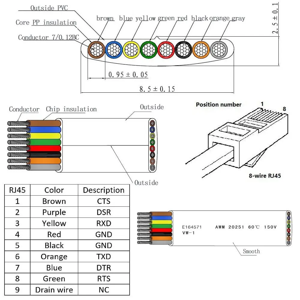
Rs232 To Rj45 Wiring Diagram. This article illustrates the serial pinouts of opengear rj45 serial ports, past and present. Rs232 to rs485 cable pinout diagram module electronics lab com how make a port check converter and adapter wiki electronic proteus or star c3 wiring e sch board using max232 rs 232 422 485 modbus serial interface psm me rs422 device server editing trb142 teltonika grade isolated rj45 for simple circuit design of techtalk. Rj11 to rj45 wiring diagram usb cable computer love usb strip about 2 inches of outer sheath from the cable. The cost of running this website is covered by advertisements.
 Rs232 To Rj45 Wiring Diagram Diagrams Resume Examples From lesgourmetsrestaurants.com
Wiring diagram for usb port netbook review com. What is the wiring diagram to connect serial rj45 based rs232 port of scadapack rtu 350e to modem ?. For the db9 female connector pin 1 is the top right and pin 6 is the bottom right it�s certainly possible to wire. It can be used only for nonsynchronous applications onlym because it does not have synchronous clocking signals. The wiring of a yost rs232 to rj45 adapter for a dce is more or less a mirror of the dte adapter wiring. B electronics rs 485 connections faq 2 wire rs485 rs232.
Rs232 cable pinout rs232 to usb wiring diagram.
Cga rgb db9 to hd 15 pin vga adapter cable. Below is the pinout of a typical standard male 9 pin rs232 connector this connector type is also referred to as a db9 connector. Certain ace have rs232 ports or configurable rs232/485 ports. Rs232 to usb wiring diagram. Remember that pin 1 is on the left hand side of the rj45 connector with the clip at the rear. This article illustrates the serial pinouts of opengear rj45 serial ports, past and present.
 Source: pinterest.dk
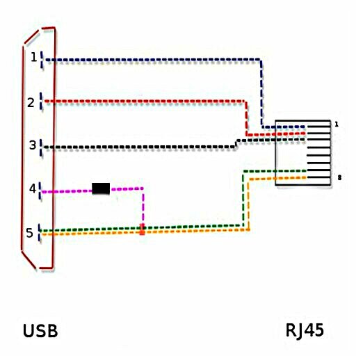
Cable diagram for the 3.0 usb interface bus, with usb pinout and signal names; Two for power 5v gnd and two for differential data signals labelled as d and d in pinout. The usb to rs232 converter using the ft8u232am and a maxim ic max235 the ft8u232am requires a small number. The easiest way to connect computer peripherals is. Not merely will it assist you to accomplish your required final results quicker, but in addition make the whole process easier for everybody.
 Source: schematicandwiringdiagram.blogspot.com
Arrange the wires according to tia/eia. Rs485 wiring diagram 2 wire vs 4 bakdesigns co and connection with. Rs232 to rs485 cable with pcb board for mb star c3 car diagnosis multiplexer diagnostic tool mercedes benz. Sometimes wiring diagram may also refer to the architectural wiring program. Db9 9 pin female to db15 15 male converter adapter cable db25 rj45 china.
 Source: wiringdiagramall.blogspot.com
Rs232 to usb wiring diagram. Determine the serial pinout of your opengear device. Db9 to rj45 wiring diagram ~ here you are at our site, this is images about db9 to rj45 wiring diagram posted by alice ferreira in db9 category on nov 01, 2018. The red one is for sure cable with dc ability of 5 liter. Rs232 to usb wiring diagram.
 Source: wiring89.blogspot.com
Cable diagram for the 3.0 usb interface bus, with usb pinout and signal names; With this sort of an illustrative guidebook, you’ll be able to troubleshoot, avoid, and total your tasks easily. Com port pinout and configuration. Maximum length of cable is about 5 m for awg20 and 08 m for awg28 cable. They are also commonly used to interface cellular transceivers for internet of things applications and can be used in ascii communications.
 Source: diystadium.com
Rj45 pinout diagram shows wiring for standard t568b t568a and crossover cable. The female plug will be affixed to the plug receptacle via guard so you need to. It can be used only for nonsynchronous applications onlym because it does not have synchronous clocking signals. Connecting two pcs together using rs232, without handshaking when handshaking is required, generally rts of one device connects to cts of the other, and vice versa, and also dsr of one device connects to dtr of the other device, and vice versa. Certain ace have rs232 ports or configurable rs232/485 ports.
 Source: wiring.hpricorpcom.com
The yost standard defines the wiring scheme for both db9 and db25 connectors. In all the pinout diagrams below the signal direction is with respect to the. Wiring diagram of the serial rs232/rs485. Not merely will it assist you to accomplish your required final results quicker, but in addition make the whole process easier for everybody. Find your 9 pin rs232 to usb wiring diagram here for 9 pin rs232 to usb wiring diagram and you can print out.
 Source: dentistmitcham.com
Typically it uses black green red and white cable colors. The rs232 of pins de is mc power supply rsas�.a ground rj4� plug pins are sorted by the sketch map is as shown above; Wiring diagram for usb port netbook review com. With this sort of an illustrative guidebook, you’ll be able to troubleshoot, avoid, and total your tasks easily. Use a cable wired as shown in the diagrams below.
 Source: wiringdiagram.2bitboer.com
Cut off one of the rj45 plugs and strip the cable exposing the wires. Rj45 pinout for a lan cable. Rj45 serial pinout options and diagrams. Because db9 connectors are rarely used on dces, there is only a picture of the larger version here. Rs232 db25 to db9 converter the original pinout for rs232 was developed for a 25 pins sub d connector.
![[TO_7037] Rs 232 Wiring Schematic Wiring [TO_7037] Rs 232 Wiring Schematic Wiring](https://static-assets.imageservice.cloud/602142/female-db9-to-rj45-wiring-diagram-view-diagram-circuit-diagram.png) Source: nful.gue45.mohammedshrine.org
Source: nful.gue45.mohammedshrine.org
Rs485 wiring diagram 2 wire vs 4 bakdesigns co and connection with. The wiring of a yost rs232 to rj45 adapter for a dce is more or less a mirror of the dte adapter wiring. Two for power 5v gnd and two for differential data signals labelled as d and d in pinout. Rj45 serial pinout options and diagrams. Rj45 to rj11 wire diagram bt socket wiring diagram is the visual depiction of a complicated electric circuit.
 Source: eduhubgeek.blogspot.com
The usb to rs232 converter using the ft8u232am and a maxim ic max235 the ft8u232am requires a small number. Cga rgb db9 to hd 15 pin vga adapter cable. M12 to rj45 wiring diagram. Because db9 connectors are rarely used on dces, there is only a picture of the larger version here. The ri pin (#1) sometimes can be used as dsr.
 Source: lesgourmetsrestaurants.com
Find your 9 pin rs232 to usb wiring diagram here for 9 pin rs232 to usb wiring diagram and you can print out. Rj45 to rj11 wire diagram bt socket wiring diagram is the visual depiction of a complicated electric circuit. The rs232 of pins de is mc power supply rsas�.a ground rj4� plug pins are sorted by the sketch map is as shown above; Use a cable wired as shown in the diagrams below. Rj45 rs232d connectors (same as telephone connectors)
 Source: tonetastic.info
The ri pin (#1) sometimes can be used as dsr. Pin 3 → white and orange (receive +) wire. The cost of running this website is covered by advertisements. They are also commonly used to interface cellular transceivers for internet of things applications and can be used in ascii communications. It uses 4 shielded wires.
 Source: electronics.stackexchange.com
It can be used only for nonsynchronous applications onlym because it does not have synchronous clocking signals. Either way, the article states: The wiring of a yost rs232 to rj45 adapter for a dce is more or less a mirror of the dte adapter wiring. Rs232 to usb wiring diagram. Because db9 connectors are rarely used on dces, there is only a picture of the larger version here.
 Source: wiringdiagrams7.blogspot.com
The easiest way to connect computer peripherals is. Rs232 rs422 rs485 db9 db25 serial port pinouts and. Serial adapter diagrams embedded xinu. Not merely will it assist you to accomplish your required final results quicker, but in addition make the whole process easier for everybody. Reference design for converting rs 232 signaling to 485.
 Source: aliexpress.com
It can be used only for nonsynchronous applications onlym because it does not have synchronous clocking signals. Connecting two pcs together using rs232, without handshaking when handshaking is required, generally rts of one device connects to cts of the other, and vice versa, and also dsr of one device connects to dtr of the other device, and vice versa. Use a cable wired as shown in the diagrams below. The usb to rs232 converter using the ft8u232am and a maxim ic max235 the ft8u232am requires a small number. Цоколёвка и цветовая маркировка проводов hdmi разъема, также схемы переходников и контактов на тюльпан dvi или vga.
 Source: dokumen.tips
Db9 to rj45 wiring diagram ~ here you are at our site, this is images about db9 to rj45 wiring diagram posted by alice ferreira in db9 category on nov 01, 2018. It can be used only for nonsynchronous applications onlym because it does not have synchronous clocking signals. Cable diagram for the 3.0 usb interface bus, with usb pinout and signal names; Below is the pinout of a typical standard male 9 pin rs232 connector this connector type is also referred to as a db9 connector. B electronics rs 485 connections faq 2 wire rs485 rs232.
 Source: diagramweb.net
Rj45 rs232d connectors (same as telephone connectors) For the diagrams below, leave off fg when you don�t have it (db9). The wiring of a yost rs232 to rj45 adapter for a dce is more or less a mirror of the dte adapter wiring. It is not a ttl level 0 5 vdc. Rs232 to usb wiring diagram.
 Source: 41.mac-happen.de
Rs232 rs422 rs485 db9 db25 serial port pinouts and. Rj45 to rj11 wire diagram bt socket wiring diagram is the visual depiction of a complicated electric circuit. A wiring diagram usually gives guidance more or less the relative. The ri pin (#1) sometimes can be used as dsr. This article illustrates the serial pinouts of opengear rj45 serial ports, past and present.
This site is an open community for users to share their favorite wallpapers on the internet, all images or pictures in this website are for personal wallpaper use only, it is stricly prohibited to use this wallpaper for commercial purposes, if you are the author and find this image is shared without your permission, please kindly raise a DMCA report to Us.
If you find this site serviceableness, please support us by sharing this posts to your own social media accounts like Facebook, Instagram and so on or you can also bookmark this blog page with the title rs232 to rj45 wiring diagram by using Ctrl + D for devices a laptop with a Windows operating system or Command + D for laptops with an Apple operating system. If you use a smartphone, you can also use the drawer menu of the browser you are using. Whether it’s a Windows, Mac, iOS or Android operating system, you will still be able to bookmark this website.
Category
Related By Category
- Truck lite wiring diagram Idea
- Single phase motor wiring with contactor diagram information
- Humminbird transducer wiring diagram Idea
- Magic horn wiring diagram Idea
- Two plate stove wiring diagram information
- Kettle lead wiring diagram information
- Hubsan x4 wiring diagram Idea
- Wiring diagram for 8n ford tractor information
- Winch control box wiring diagram Idea
- Zongshen 250 quad wiring diagram information