Ro filter wiring diagram Idea
Home » Trending » Ro filter wiring diagram Idea
Your Ro filter wiring diagram images are available. Ro filter wiring diagram are a topic that is being searched for and liked by netizens now. You can Find and Download the Ro filter wiring diagram files here. Get all royalty-free vectors.
If you’re searching for ro filter wiring diagram pictures information related to the ro filter wiring diagram keyword, you have pay a visit to the right blog. Our website always gives you hints for seeing the maximum quality video and picture content, please kindly hunt and locate more informative video content and graphics that fit your interests.
Ro Filter Wiring Diagram. If either the line or the phone connection is to be. Low pressure switch * these stages optional depends on your ro model ) What is a low pass filter tutorial on the basics of passive rc filters technical articles. A band pass filter is a circuit which allows only particular band of frequencies to pass through it.
 wiring diagram of ro water purifier Hindi part 2 YouTube From youtube.com
Using edrawmax to create your own wiring diagram. Purchase float switch click this link. Diagram 5 stage ro with uv and booster pump. Low pass rc active filter a and the frequency response scientific diagram. Click on the link diagram 5 stage ro+uv w/booster and you will be transferred to the diagram. The 3 stage, 4 stage and 5 stage reverse osmosis systems install exactly the same.
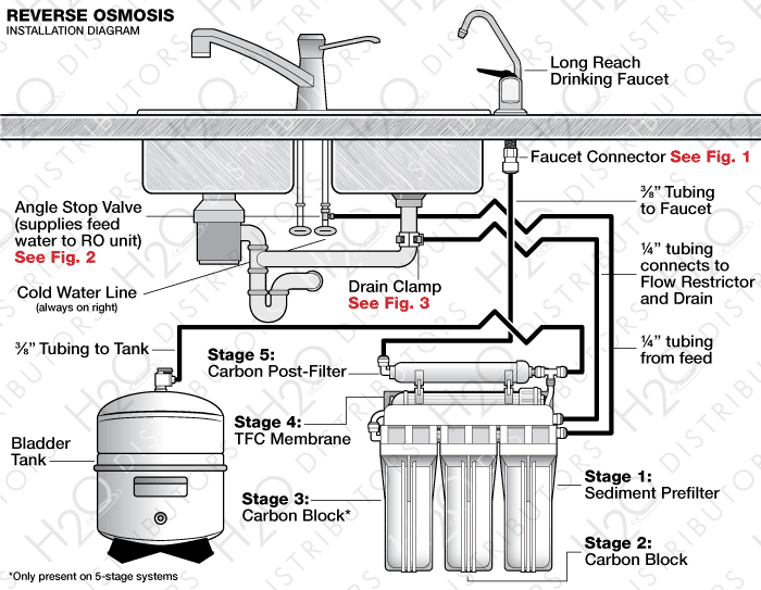
The 3 stage, 4 stage and 5 stage reverse osmosis systems install exactly the same.
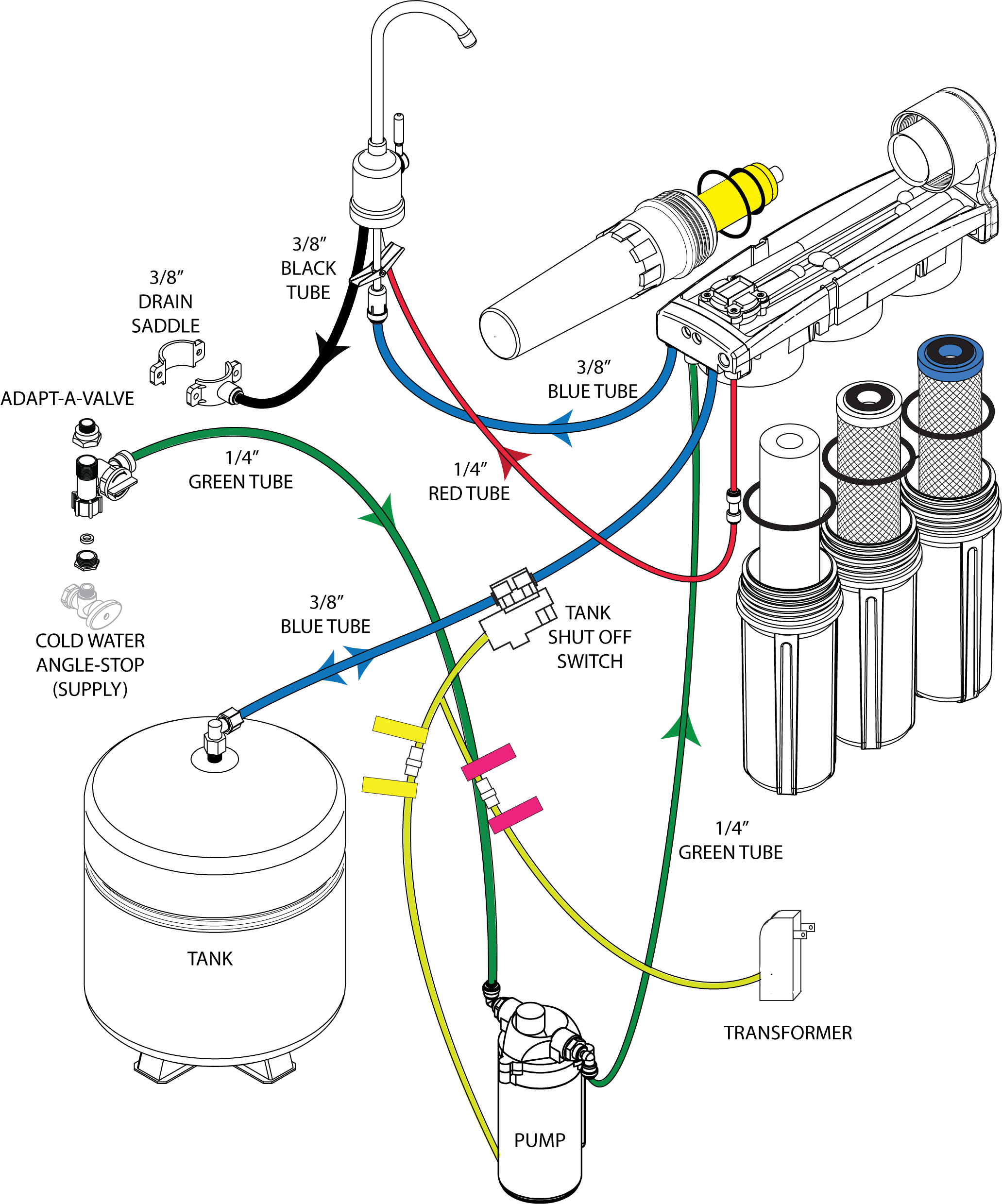
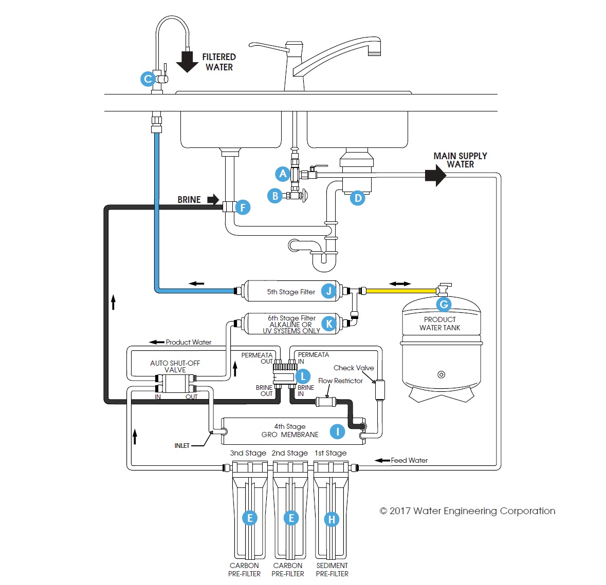
If either the line or the phone connection is to be. Click on the link * diagram 5 stage ro+uv w/booster * and you will be transferred to the diagram. diagram 5 stage ro+uv w/booster this is a diagram of a 5 stage reverse osmosis system with a uv light and a booster pump. Initials part qty factory order no completion date sch date operator sheet of revision description status date drawing no. For example, always a for battery. Refer to the appropriate float arrangement diagram for the correct terminal connections for your system.
Source: hanenhuusholli.blogspot.com
A band pass filter is a circuit which allows only particular band of frequencies to pass through it. Click on the link diagram 5 stage ro+uv w/booster and you will be transferred to the diagram. Refer to the panel wiring diagram for the correct terminal connections for your system. A comprehensive overview of the cost, installation process and maintenance of the rainsoft water treament systems specifically the ec4. Main disconnect provided by others.
 Source: mickygurlz.blogspot.com
It�s no fault of yours you do not know. 45 to 90hz hum filter circuit diagram: Within bs en 60204 there are references to other standards including bs en 60947. The 3 stage, 4 stage and 5 stage reverse osmosis systems install exactly the same. General purchase audio preamplifier based on pair of 2n2222 transistors:
 Source: wiringdiagrammechanic.blogspot.com
Reverse osmosisro control panel circuit diagram,astero control panel price,ro plant control panel wiring,ro controller,ro membrane manufacturers in india,chemical for ro plant,astero 13 panel price,wtp panel,astero control panel price,ro control panel cir. Initials part qty factory order no completion date sch date operator sheet of revision description status date drawing no. General purchase audio preamplifier based on pair of 2n2222 transistors: A band pass filter is a circuit which allows only particular band of frequencies to pass through it. Click on the link * diagram 5 stage ro+uv w/booster * and you will be transferred to the diagram.
 Source: pinterest.com
Drawn by scale issued date. Make sure the ro membrane is inserted correctly. Kia wiring diagrams free download for such models, as: Connect the wires coming from the floats to the terminals in the control panel. I just worry that you may stuff something up.
 Source: youtube.com
The diagram shows all you need. Wire nut to connect the neutral block of the pump with the controls neutral block and with the incoming neutral line. A well defined wiring diagram considerably reduces the wiring efforts and minimizes the possibilities of errors during the actual installation. For example, always a for battery. Initials part qty factory order no completion date sch date operator sheet of revision description status date drawing no.
 Source: kovodym.blogspot.com
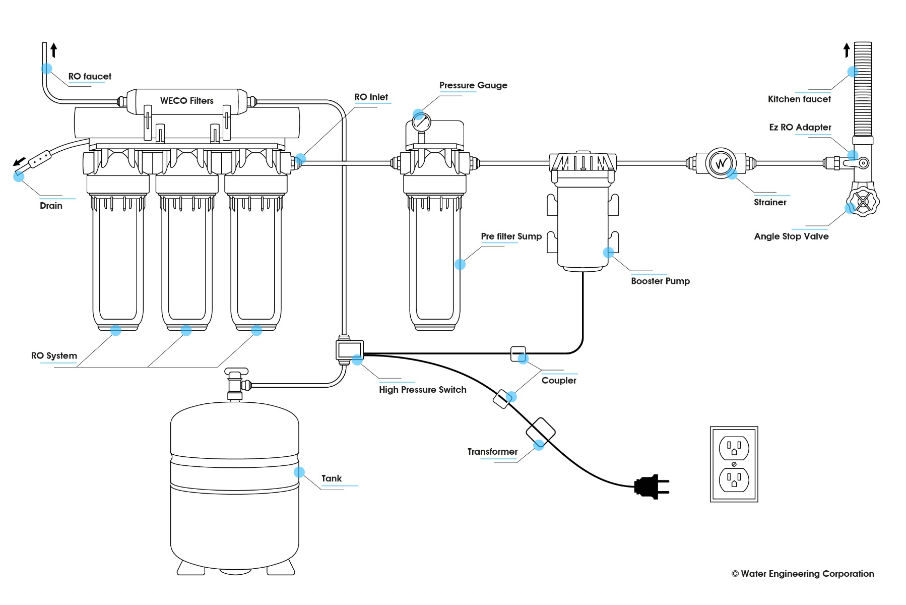
Within bs en 60204 there are references to other standards including bs en 60947. It�s no fault of yours you do not know. diagram 5 stage ro+uv w/booster this is a diagram of a 5 stage reverse osmosis system with a uv light and a booster pump. A bracket is provided so they can be mounted under the sink or in a basement. Angle stop valve the angle stop valve connects to the cold water line to supply water to the ro system and provides an easy ability to shut off the water supply.
 Source: wecofilters.com
Power wiring options terminal strip 00025 etm controls neutral ground green controls l1 note: A bracket is provided so they can be mounted under the sink or in a basement. The only difference is the addition of a carbon water filter before the membrane on the 4 stage ro system and two of. In all wiring diagrams the same component designation (code) is used for a particular component; Motors must have interal ov dp c for float arrangement diagram, see drawing no.
 Source: kovodym.blogspot.com
Diagram 5 stage ro with uv and booster pump. The only difference is the addition of a carbon water filter before the membrane on the 4 stage ro system and two of. 1 low pass filter a bode plot consisting of the amplitude frequency scientific diagram. I was not inferring that at all. The 3 stage, 4 stage and 5 stage reverse osmosis systems install exactly the same.
Source: skippingtheinbetween.blogspot.com
A comprehensive overview of the cost, installation process and maintenance of the rainsoft water treament systems specifically the ec4. A band pass filter is a circuit which allows only particular band of frequencies to pass through it. Initials part qty factory order no completion date sch date operator sheet of revision description status date drawing no. Navigate to [new]> [electrical engineering]> [basic electrical] step 3: The diagram shows all you need.
 Source: tianpinyt.blogspot.com
diagram 5 stage ro+uv w/booster this is a diagram of a 5 stage reverse osmosis system with a uv light and a booster pump. If either the line or the phone connection is to be. There is additional information about installation of a ro system on this web site. Low pressure switch * these stages optional depends on your ro model ) Sound alarm based on lm741 opamp and lm386 amplifier:
 Source: greenbuildermedia.com
Diagram 5 stage ro with uv and booster pump. The diagram shows all you need. Drawn by scale issued date. I just worry that you may stuff something up. A wiring diagram is a simple visual representation of the physical connections and physical layout of an electrical system or circuit.
 Source: atkinsjewelry.blogspot.com
If either the line or the phone connection is to be. Refer to the appropriate float arrangement diagram for the correct terminal connections for your system. Connect the wires coming from the floats to the terminals in the control panel. Purchase float switch click this link. There is additional information about installation of a ro system on this web site.
 Source: kovodym.blogspot.com
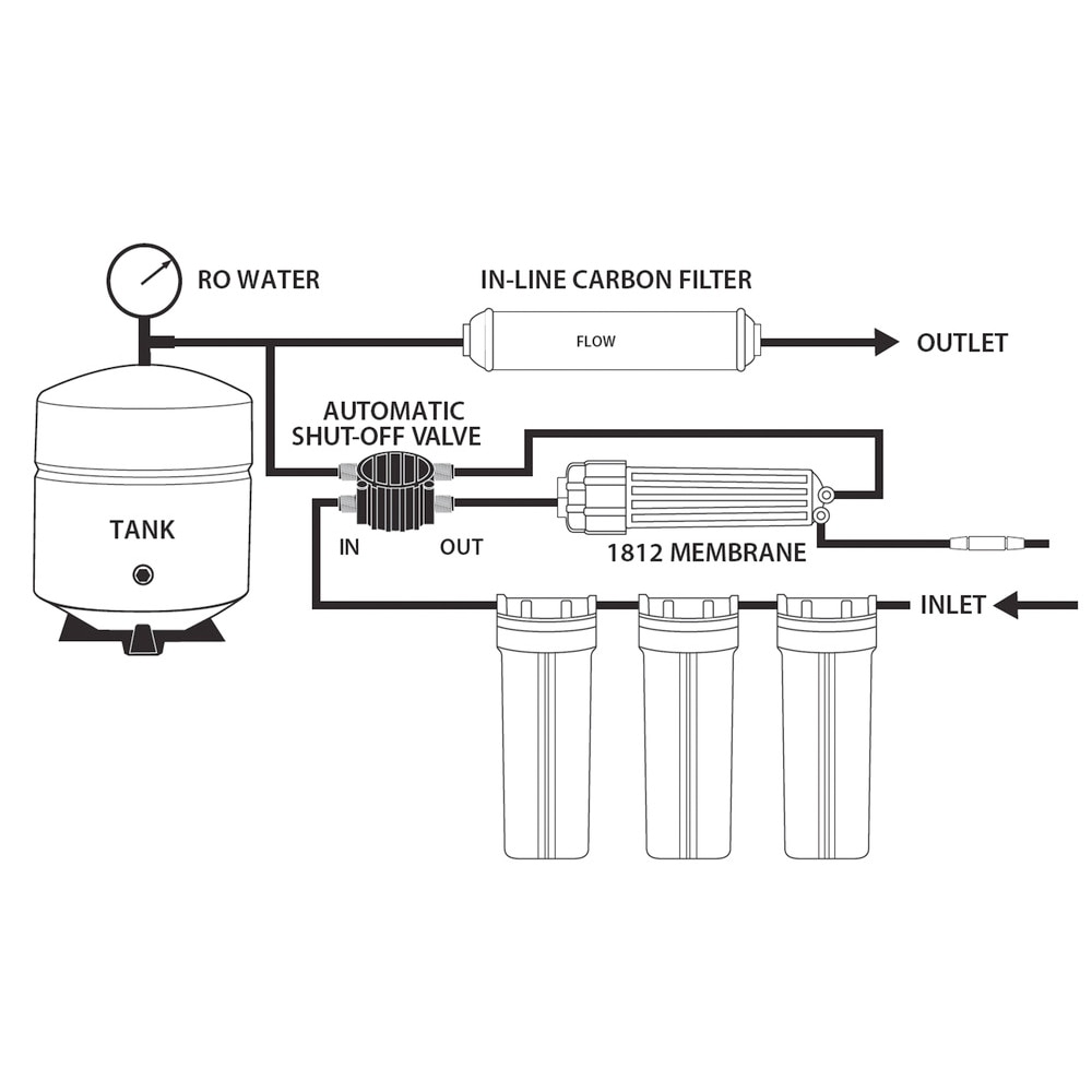
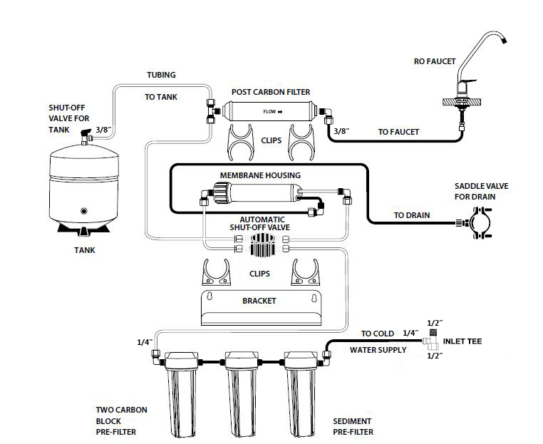
Main disconnect provided by others. Reverse osmosisro control panel circuit diagram,astero control panel price,ro plant control panel wiring,ro controller,ro membrane manufacturers in india,chemical for ro plant,astero 13 panel price,wtp panel,astero control panel price,ro control panel cir. Uv purifier / post active carbon filter: Navigate to [new]> [electrical engineering]> [basic electrical] step 3: Installation diagram of 4 stage reverse osmosis systems.
 Source: galvinconanstuart.blogspot.com
General purchase audio preamplifier based on pair of 2n2222 transistors: It�s no fault of yours you do not know. Motors must have interal ov dp c for float arrangement diagram, see drawing no. Refer to the panel wiring diagram for the correct terminal connections for your system. Commercial reverse osmosis system diagram engineered in usa by pure aqua, inc.
 Source: aquatekpro.com
Navigate to [new]> [electrical engineering]> [basic electrical] step 3: Commercial reverse osmosis system diagram engineered in usa by pure aqua, inc. There is additional information about installation of a. I was not inferring that at all. Purchase water filter use smps power supply click this link.
![]() Source: flixwater.com
Source: flixwater.com
- insert membrane into housing in the wrong direction. Main disconnect provided by others. Ro pump motor purchase click this link. There is additional information about installation of a ro system on this web site. Purchase float switch click this link.
 Source: skippingtheinbetween.blogspot.com
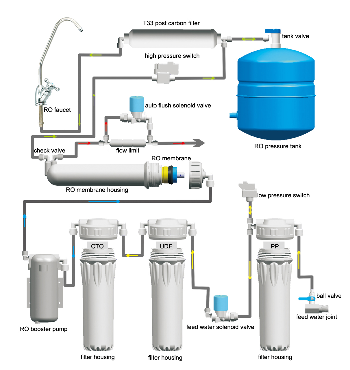
The following photos, circuit diagram and text try to describe how adsl filter sold by elexi (product number adsl puhelinsovitin usa/usa gp4c) works. diagram 5 stage ro+uv w/booster this is a diagram of a 5 stage reverse osmosis system with a uv light and a booster pump. Initials part qty factory order no completion date sch date operator sheet of revision description status date drawing no. For example, always a for battery. Reverse osmosisro control panel circuit diagram,astero control panel price,ro plant control panel wiring,ro controller,ro membrane manufacturers in india,chemical for ro plant,astero 13 panel price,wtp panel,astero control panel price,ro control panel cir.
 Source: skippingtheinbetween.blogspot.com
For example, always a for battery. Initials part qty factory order no completion date sch date operator sheet of revision description status date drawing no. What is a low pass filter tutorial on the basics of passive rc filters technical articles. When reading wiring diagrams, a technician doesn’t get to see the internal diagrams for control units and so we don’t concern ourselves with their workings. It�s no fault of yours you do not know.
This site is an open community for users to submit their favorite wallpapers on the internet, all images or pictures in this website are for personal wallpaper use only, it is stricly prohibited to use this wallpaper for commercial purposes, if you are the author and find this image is shared without your permission, please kindly raise a DMCA report to Us.
If you find this site convienient, please support us by sharing this posts to your favorite social media accounts like Facebook, Instagram and so on or you can also save this blog page with the title ro filter wiring diagram by using Ctrl + D for devices a laptop with a Windows operating system or Command + D for laptops with an Apple operating system. If you use a smartphone, you can also use the drawer menu of the browser you are using. Whether it’s a Windows, Mac, iOS or Android operating system, you will still be able to bookmark this website.
Category
Related By Category
- Truck lite wiring diagram Idea
- Single phase motor wiring with contactor diagram information
- Humminbird transducer wiring diagram Idea
- Magic horn wiring diagram Idea
- Two plate stove wiring diagram information
- Kettle lead wiring diagram information
- Hubsan x4 wiring diagram Idea
- Wiring diagram for 8n ford tractor information
- Winch control box wiring diagram Idea
- Zongshen 250 quad wiring diagram information