Rgb led wiring diagram information
Home » Trend » Rgb led wiring diagram information
Your Rgb led wiring diagram images are available. Rgb led wiring diagram are a topic that is being searched for and liked by netizens today. You can Find and Download the Rgb led wiring diagram files here. Download all royalty-free photos.
If you’re searching for rgb led wiring diagram images information linked to the rgb led wiring diagram interest, you have pay a visit to the right blog. Our website frequently gives you suggestions for refferencing the highest quality video and image content, please kindly surf and locate more enlightening video articles and images that fit your interests.
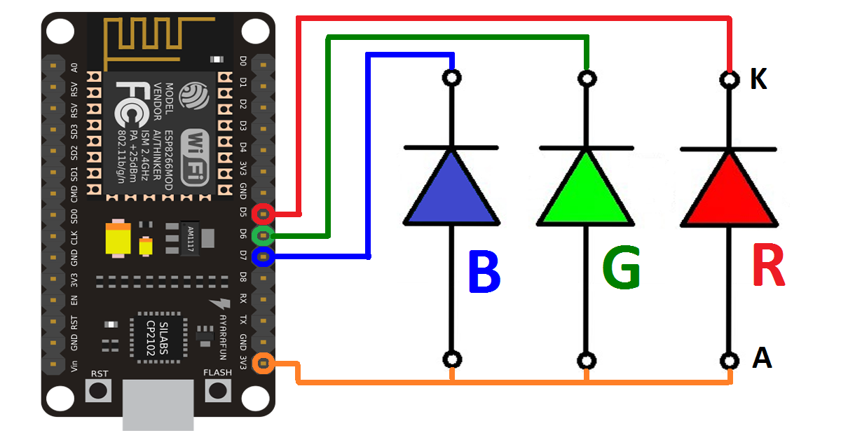
Rgb Led Wiring Diagram. Wiring 3 color rgb smd common cathode led. Wiring diagram includes several comprehensive illustrations that present the connection of various items. This grounds all of the led grounds. Rgbw led strip wiring diagram.
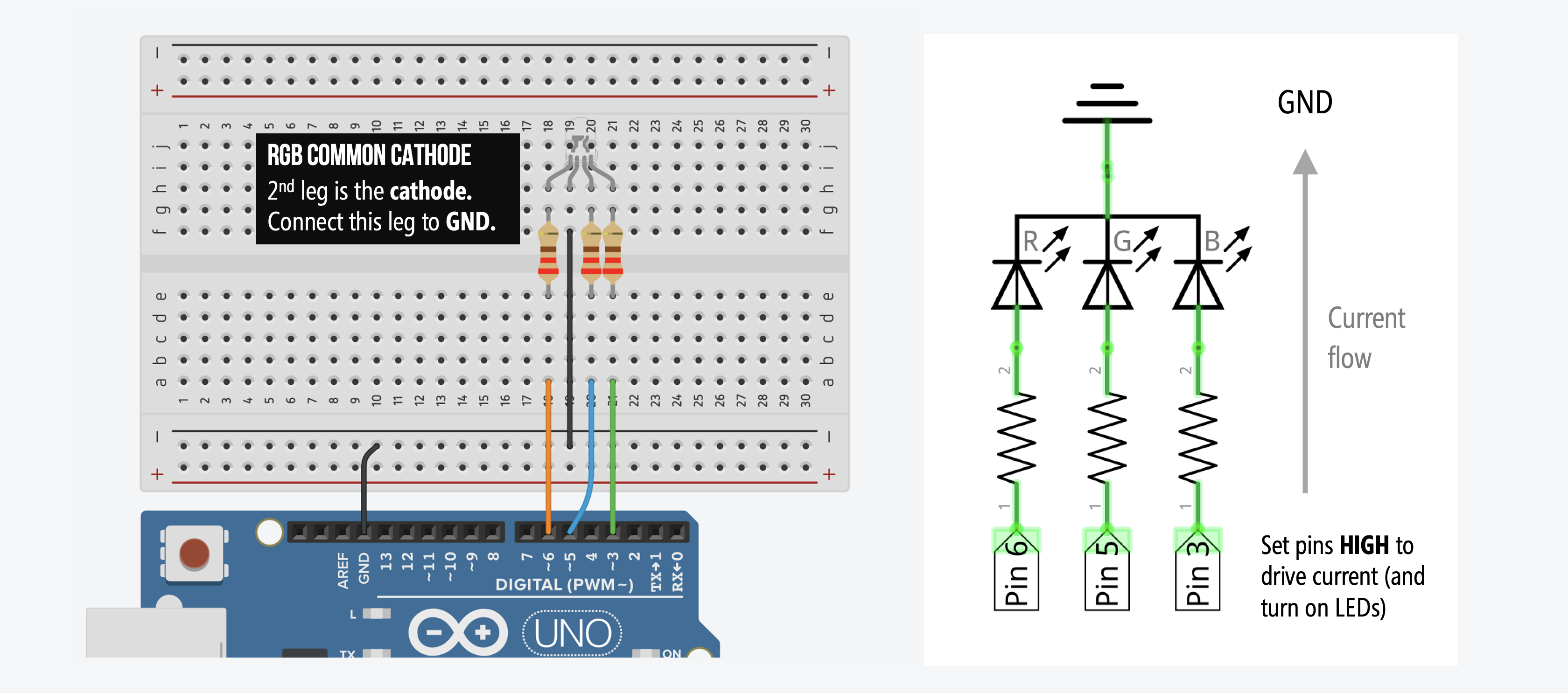 L6 Crossfading RGB LEDs Physical Computing From makeabilitylab.github.io
Rgb fan wiring diagram wiring diagram line wiring diagram. It is a context for learning fundamentals of computer programming and prototyping with electronics within the context of the electronic arts. Rgb led cooling fan 12cm cooler with remote controller u7h4 silen c2g0 v0u6 gaming r4x4 n9t0 sho polska. Wiring 3 color rgb smd common cathode led. Otherwise, the structure won’t function as it ought to be. Cut away the waterproof overmolding at one end of the strip.
Red green and blue wires are the grounds for the led that is the same color as the wire.
To fan rpm ecosystems guides and tutorials linus tech tips single connection confusion techpowerup forums gzdl 3 6 pcs led multi couleur computer case pc cooling avec télécommande acheter à prix bas livraison gratuite avis. Wiring 3 color rgb smd common cathode led. Scrape away the rubber to expose the copper pads. View 37 argb fan problem chassis tt community. It is a context for learning fundamentals of computer programming and prototyping with electronics within the context of the electronic arts. Please use the included wiring guide for that product.
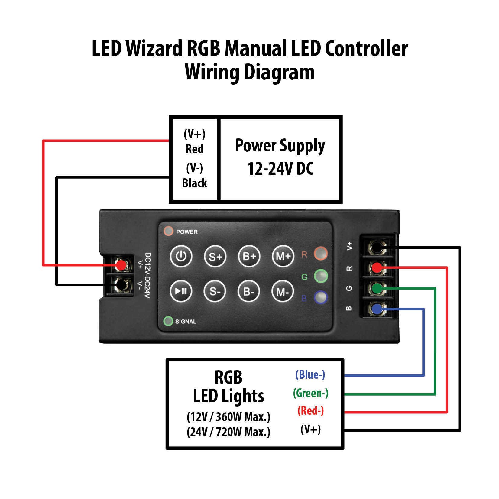 Source: solidapollo.com
View 37 argb fan problem chassis tt community. Insert as far as possible. Rgb led cooling fan 12cm cooler with remote controller u7h4 silen c2g0 v0u6 gaming r4x4 n9t0 sho polska. And then we connect all of the toggle switches to positive voltage and ground, so that we can turn off or on whichever led. Dim cct rgbw rgb 4 in 1 constant voltage zigbee led controller sr zg1029 5c.

But [paul stoffregen] has an thrilling answer. And then we connect all of the toggle switches to positive voltage and ground, so that we can turn off or on whichever led. Connecting an rgb strip and a white led strip. Wiring diagram includes several comprehensive illustrations that present the connection of various items. But they�re almost the same.
 Source: diykeyboards.com
T8 led wiring diagram 4 bulb ballast wiring diagram gallery electrical wiring diagram rh metroroomph t12 to t8 ballast wiring t8 ballast wiring. Learn how to use rgb led with arduino, how to connect rgb led to arduino, how to code for rgb led, how to program arduino step by step. And then we connect all of the toggle switches to positive voltage and ground, so that we can turn off or on whichever led. By facybulka posted on december 9, 2015 24 views. Wiring diagram includes several comprehensive illustrations that present the connection of various items.
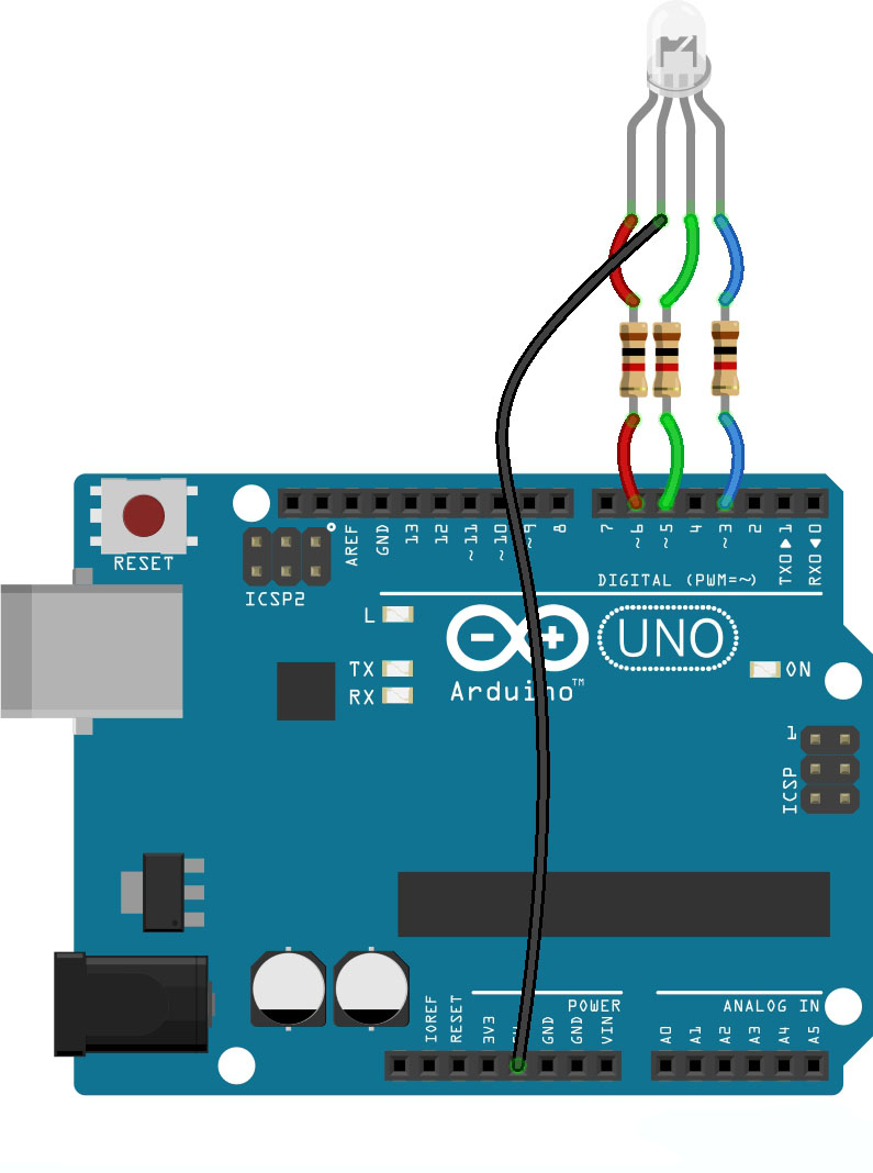 Source: teachmemicro.com
Cut away the waterproof overmolding at one end of the strip. Wiring diagram includes several comprehensive illustrations that present the connection of various items. To fan rpm ecosystems guides and tutorials linus tech tips single connection confusion techpowerup forums gzdl 3 6 pcs led multi couleur computer case pc cooling avec télécommande acheter à prix bas livraison gratuite avis. Please use the included wiring guide for that product. Erik dörnenburg an arduino digital led.
 Source: microcontrollerkits.blogspot.com
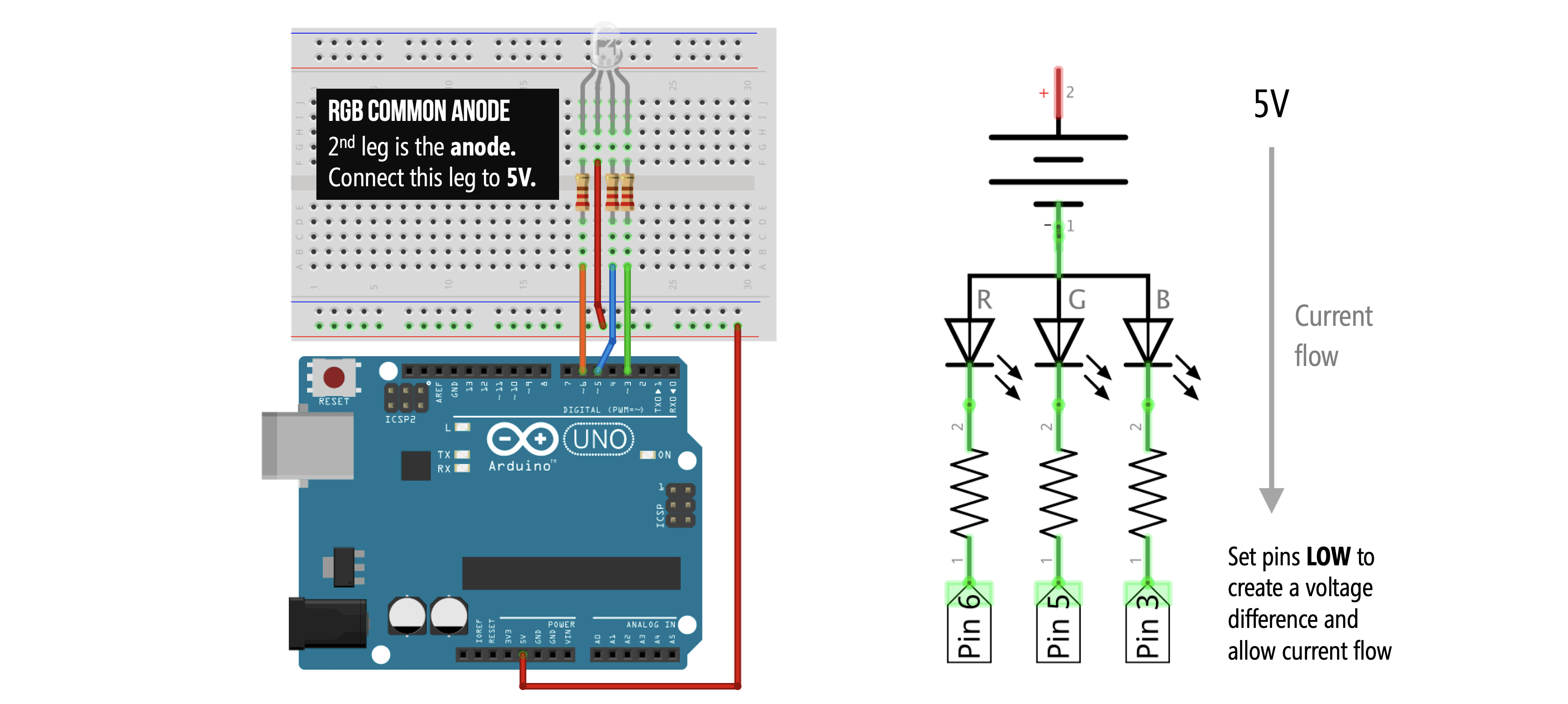
Insert as far as possible. This wiring diagram shows you how to connect an rgb led to the arduino board. Rgb lights junction box (supplied by other) 4c/16 cable (supplied by other) rgb lights #1 rgb lights #2 rgb lights patch cable (supplied with light) tape plug end pic #6: Building rgb led displays is one of the most thrilling. The guide incorporates a great deal of.
 Source: makeabilitylab.github.io
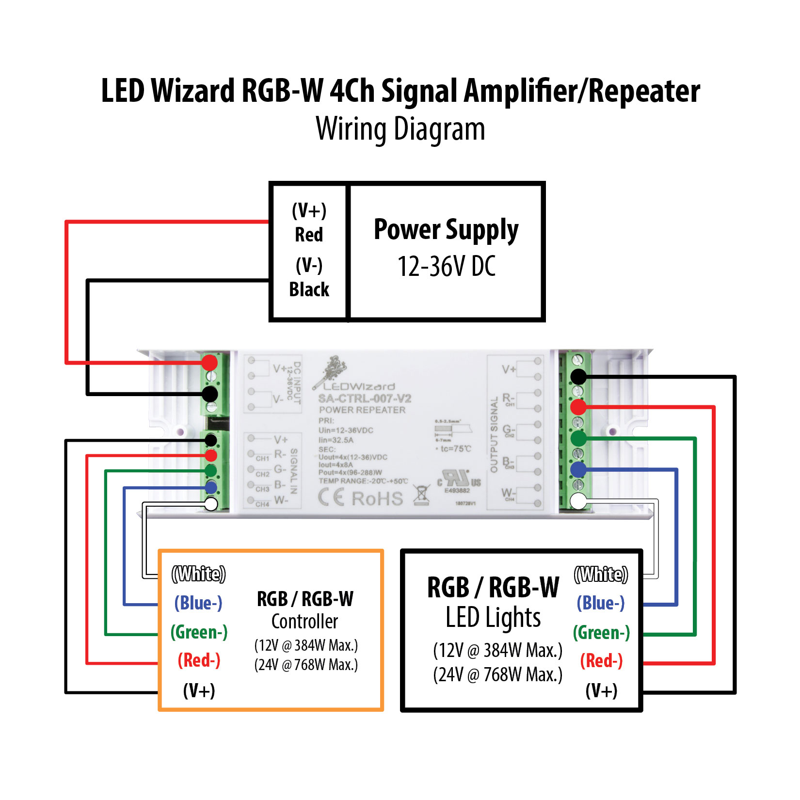
Insert rgb strip into connector opening, being careful to match wire color with color labels on the flex strip. Schematic rgb led strips adafruit learning system non addressable strip guide learn sparkfun com light controller circuits homemade circuit projects internal and voltage information waveform lighting diagram neopixel bracelet with arduino under repository 21018 next gr controlling circuitlab smartphone operated build a homekit enabled wifi blake drayson ironic. Rgb led wiring diagram 5050 rgb led strip wiring diagram lumenier rgb led wiring diagram rgb led light strip wiring diagram every electrical arrangement is made up of various different parts. Please use the included wiring guide for that product. My immediate thoughts are as shown in the attached schematic.
 Source: solidapollo.com
The three coloured wires should correspond with the r, g and b ports on. Otherwise, the structure won’t function as it ought to be. It is a context for learning fundamentals of computer programming and prototyping with electronics within the context of the electronic arts. Rgb led wiring diagram 5050 rgb led strip wiring diagram lumenier rgb led wiring diagram rgb led light strip wiring diagram every electrical arrangement is made up of various different parts. Wiring diagram includes several comprehensive illustrations that present the connection of various items.
 Source: untpikapps.com
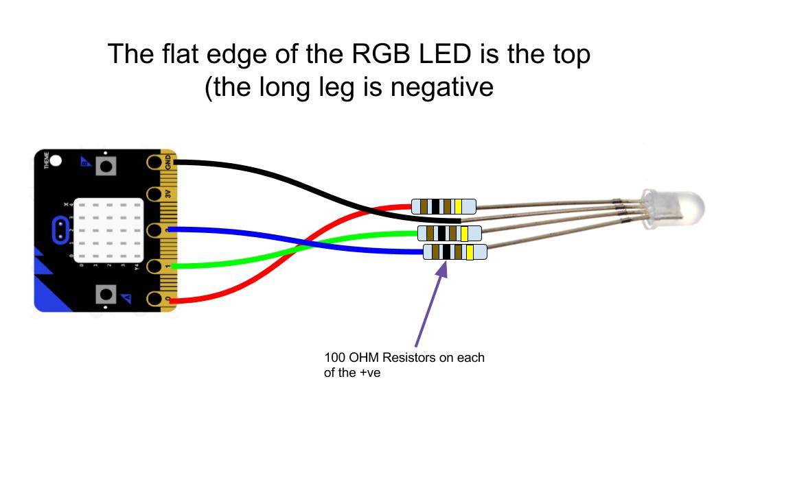
Cut away the waterproof overmolding at one end of the strip. Wiring diagram includes several comprehensive illustrations that present the connection of various items. In our example, we are using the wiring for the common cathode rgb led. The only difference is that the second lead of the rgb led from the left is connected to the 5v pin of the arduino uno for the common anode while for the common cathode, the second lead is connected to gnd. The diagram at the following link shows the internal layout of the rgb led:
 Source: learnlearn.uk
Rgb led remote controller 22 modes with color wheel 12 24v input dimming sd 288w rf control works up to 50ft away. And then we connect all of the toggle switches to positive voltage and ground, so that we can turn off or on whichever led. Learn how to use rgb led with arduino, how to connect rgb led to arduino, how to code for rgb led, how to program arduino step by step. Well, we have the answer: Demonstrates the use of pwm pins (analog output) to change the color of an rgb led.
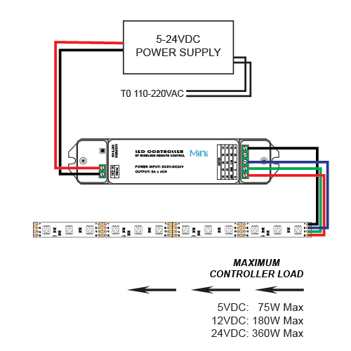 Source: hudafukuda.blogspot.com
The bottom of the flex strip should be touching the black piece. Gelid solutions stella daisy chain. The overall effect produced by this project is a glowing sequence of lights changing slowly from one colour to the next. Rgb fan wiring diagram wiring diagram line wiring diagram. The bottom of the flex strip should be touching the black piece.
 Source: schematron.org
Building rgb led displays is one of the most thrilling. Be sure the relay power capacity exceeds the amperage of your light bar’s maximum current draw. Dim cct rgbw rgb 4 in 1 constant voltage zigbee led controller sr zg1029 5c. The only difference is that the second lead of the rgb led from the left is connected to the 5v pin of the arduino uno for the common anode while for the common cathode, the second lead is connected to gnd. This is the smd rgb led common cathode module, these module has 3 separate leds the red, green and blue which can be individually driven by applying a voltage to the appropriate module pin this example code is uses the arduino analogwrite (pwm) function to cycle through the full possible output colors.
 Source: pinterest.com
Insert rgb strip into connector opening, being careful to match wire color with color labels on the flex strip. But [paul stoffregen] has an thrilling answer. Each component ought to be placed and connected with other parts in particular way. Rgbw led strip wiring diagram. Note that this is a common cathode led, in which the longer pin is connected to ground, further ahead i’ll explain what common cathode means.
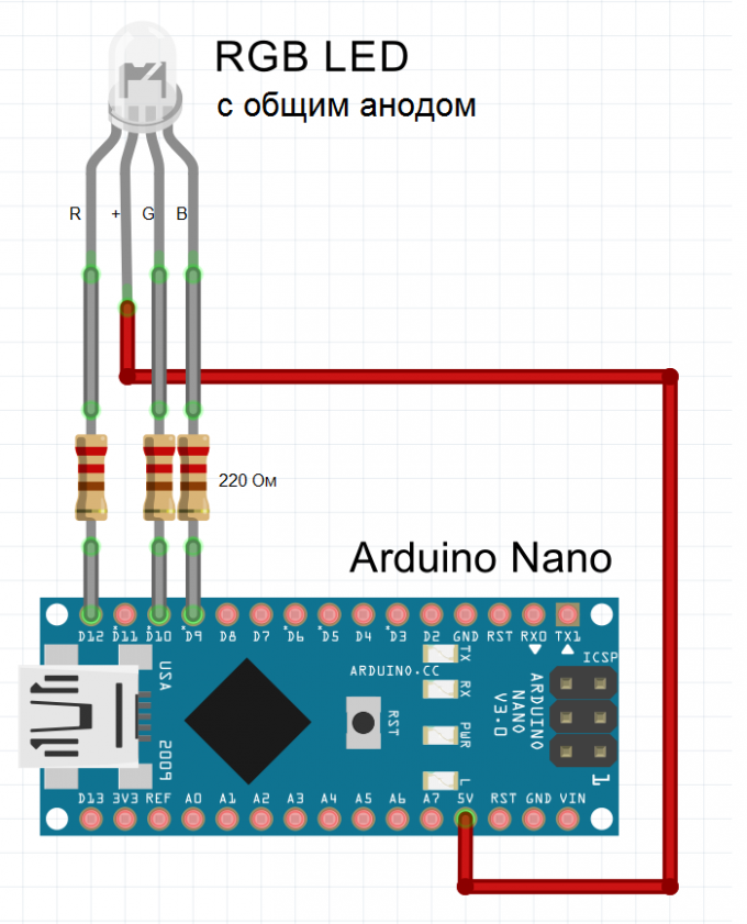 Source: eng.kakprosto.ru
Rgbw led strip wiring diagram. By facybulka posted on december 9, 2015 24 views. 3 pin and 4 fan wire diagrams cooler master faq. Otherwise, the structure won’t function as it ought to be. Rgb fan wiring diagram wiring diagram line wiring diagram.
 Source: arduinogetstarted.com
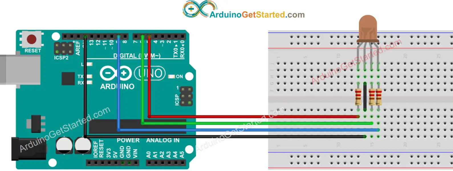
This wiring diagram shows you how to connect an rgb led to the arduino board. Rgb lights junction box (supplied by other) 4c/16 cable (supplied by other) rgb lights #1 rgb lights #2 rgb lights patch cable (supplied with light) tape plug end pic #6: Erik dörnenburg an arduino digital led. Find this and other arduino tutorials on arduinogetstarted.com. Wiring diagram custom billet ons.
 Source: makeabilitylab.github.io
Otherwise, the structure won’t function as it ought to be. So with common cathode rgb leds, we connect pin 2 to ground. This is the smd rgb led common cathode module, these module has 3 separate leds the red, green and blue which can be individually driven by applying a voltage to the appropriate module pin this example code is uses the arduino analogwrite (pwm) function to cycle through the full possible output colors. Internal diagram of a common cathode rgb. On wiring v1 boards the pwm.
 Source: electronics.stackexchange.com
Sure there are rgb leds and those are fun too but what comes after that? This wiring guide covers most products that rgbhalokits sells. This wiring diagram is the answer! 3 cutting rgb flexible led strip step 2. By facybulka posted on december 9, 2015 24 views.
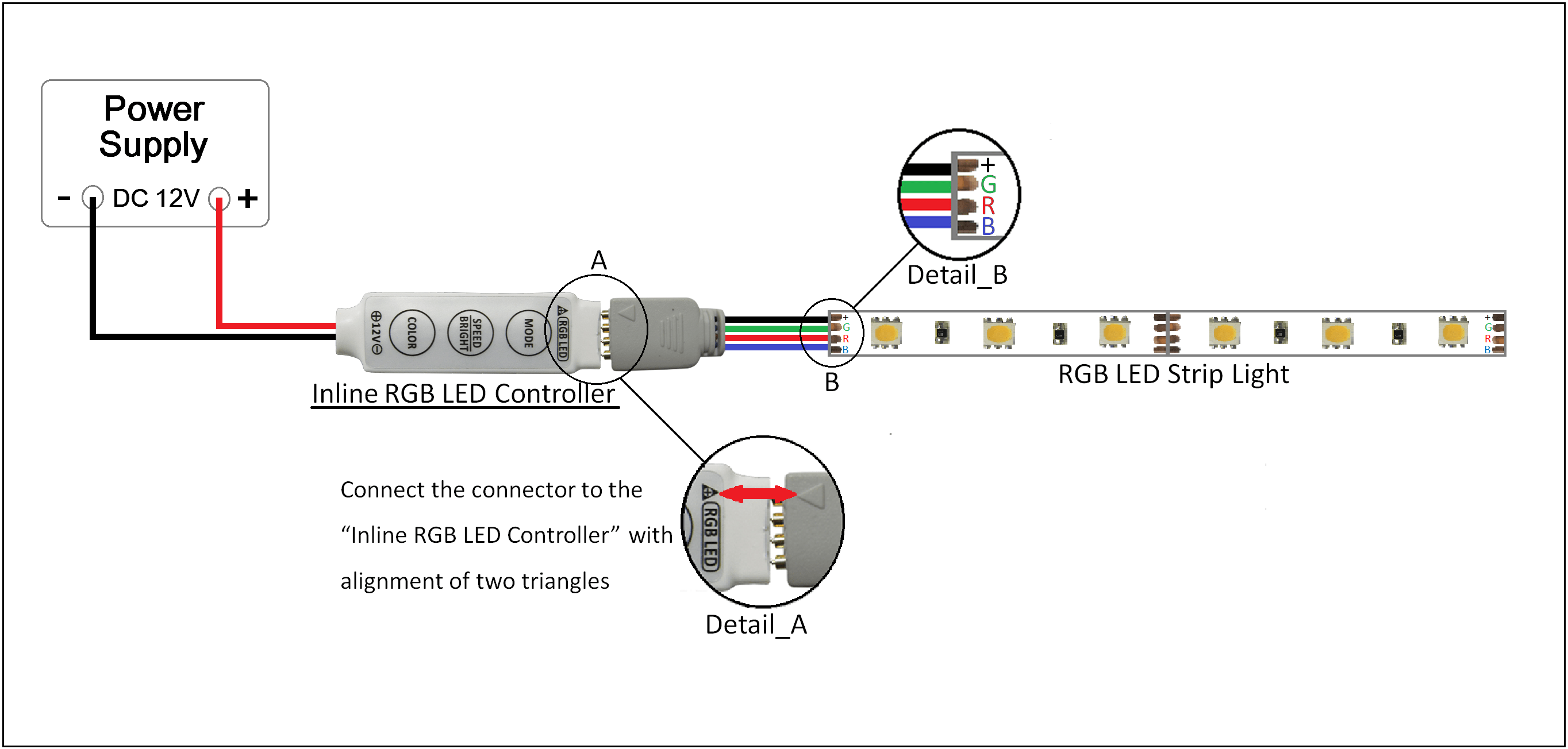 Source: oznium.com
Here s a picture of the completed rainbow led. But [paul stoffregen] has an thrilling answer. Rgb fan wiring diagram wiring diagram line wiring diagram. It contains instructions and diagrams for various types of wiring strategies and other things like lights, home windows, and so on. These are flexible circuit boards with full color leds soldered on.
 Source: untpikapps.com
The bottom of the flex strip should be touching the black piece. The overall effect produced by this project is a glowing sequence of lights changing slowly from one colour to the next. So with common cathode rgb leds, we connect pin 2 to ground. In imitation of aggravating to remove, replace or fix the wiring in an automobile, having an accurate and detailed rgb led strip wiring diagram is. Demonstrates the use of pwm pins (analog output) to change the color of an rgb led.
This site is an open community for users to do submittion their favorite wallpapers on the internet, all images or pictures in this website are for personal wallpaper use only, it is stricly prohibited to use this wallpaper for commercial purposes, if you are the author and find this image is shared without your permission, please kindly raise a DMCA report to Us.
If you find this site adventageous, please support us by sharing this posts to your own social media accounts like Facebook, Instagram and so on or you can also save this blog page with the title rgb led wiring diagram by using Ctrl + D for devices a laptop with a Windows operating system or Command + D for laptops with an Apple operating system. If you use a smartphone, you can also use the drawer menu of the browser you are using. Whether it’s a Windows, Mac, iOS or Android operating system, you will still be able to bookmark this website.
Category
Related By Category
- Predator 670 engine wiring diagram Idea
- Frsky x8r wiring diagram information
- Pioneer ts wx130da wiring diagram Idea
- Johnson 50 hp wiring diagram Idea
- Kohler voltage regulator wiring diagram Idea
- Johnson 50 hp outboard wiring diagram information
- Kti hydraulic remote wiring diagram Idea
- Pyle plpw12d wiring diagram information
- Tx9600ts wiring diagram information
- Lifan 50cc wiring diagram information