Retic solenoid wiring diagram Idea
Home » Trending » Retic solenoid wiring diagram Idea
Your Retic solenoid wiring diagram images are available. Retic solenoid wiring diagram are a topic that is being searched for and liked by netizens today. You can Get the Retic solenoid wiring diagram files here. Get all free vectors.
If you’re searching for retic solenoid wiring diagram pictures information linked to the retic solenoid wiring diagram interest, you have visit the ideal site. Our website frequently provides you with hints for viewing the highest quality video and image content, please kindly hunt and locate more informative video content and images that fit your interests.
Retic Solenoid Wiring Diagram. This connects the valve directly to 24vac. These starters come in different sizes depending on the model of your vehicle. The master or pump port will send a signal activating the master solenoid if your system runs off the mains water supply or will activate your water bore pump via a low voltage relay. Run a single wire from the p/mv terminal on the controller to the other yellow wire on the pump start relay.
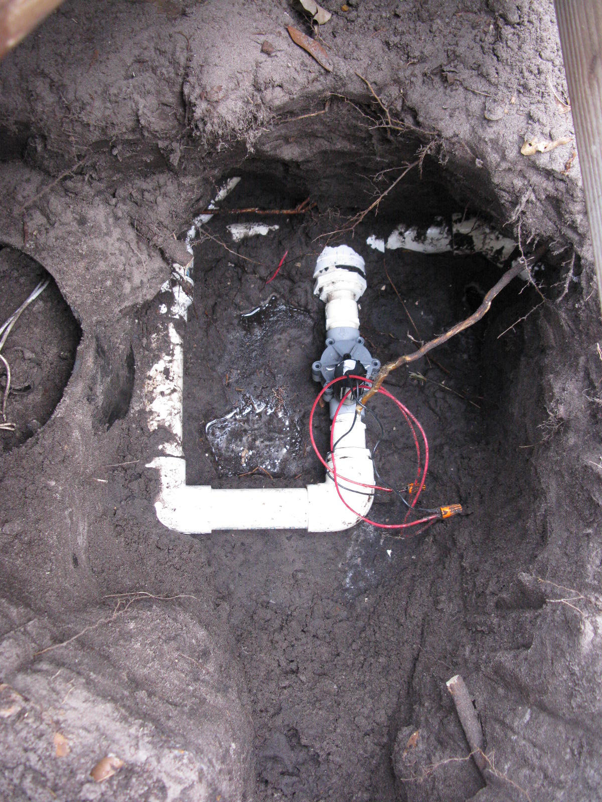 Retic Solenoid Wiring Diagram INHERENTLYROMANTIC From inherentlyromantic.blogspot.com
Pin 2 intake air control valve solenoid. Don’t connect wires into terminals that will not be used. The mainline of a retic system is the pipes that go downstream from the now disconnected master solenoid valve near the water meter all the way to any of the individual solenoid valves that operate any of the stations (zones). Route wire through the conduit or one of the openings on the bottom of the cabinet. Get your solution here, right now! So when you set your controller make note of which function you are operating in the dial and just set the one start time.
Get your solution here, right now!
So when you set your controller make note of which function you are operating in the dial and just set the one start time. Wire the solenoid valves and pump / master valve (if used) as per the wiring diagram. • permanent memory for the retention of all programmed information. Most perth retic systems have the solenoid valves in groups. Put the joiner onto the pvc pipe and screw the solenoid onto the joiner. Every irrigation has a common wire that connects all of the solenoids together and in most cases it is a black wire, as this is the colour most commonly used.
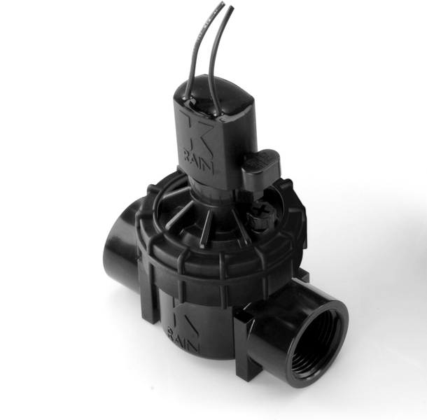 Source: brightonreticulation.com
Also double check the fuse on the board, and the breaker box to make sure ac is valid. One of them is that the fault with your car starter could be some issues with the terminals or the wires that connect your solenoid. All wire connections should be done using waterproof connectors. Try touching the common wire to the left terminal while you touch the vavle wire to the right one as you did before. Check all connections to ensure they are wired correctly and are secure.
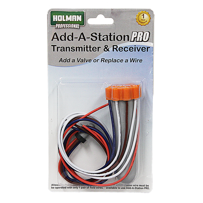 Source: reticcontrollerman.com
6 tape and screw your first thread join to the pressure point At the master valve, attach the common wire to either solenoid wire of the valve. At valves, attach a common wire to either solenoid wire on all valves. Control box joondalup retic and turf perth reticulation retic and turf north of perth retic repairs perth reticulation installation. Route wire through the conduit or one of the openings on the bottom of the cabinet.
 Source: youtube.com
One group or manifold for the front yard and one for the back. Attach a separate control wire to the remaining wire of each valve. At the master valve, attach the common wire to either solenoid wire of the valve. All wire connections should be done using waterproof connectors. • weather resistant controller with 240vac power lead and plug.
 Source: virginbores.com.au
If a common wire gets cut then all of the solenoids that it connects together will be out of action. This can scratch the nozzle. Most perth retic systems have the solenoid valves in groups. Attach a separate control wire to the remaining solenoid wire. These starters come in different sizes depending on the model of your vehicle.
 Source: waterboretroubleshootersperth.com
Sometimes the solenoids are spaced separately along the main line front to rear as in the plan shown. Have an irrigation question or problem? You only need 1 start time! Wiring sensors is quite simple. Check all connections to ensure they are wired correctly and are secure.
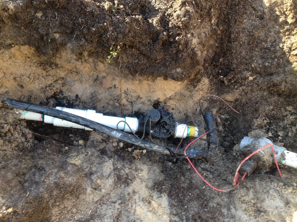 Source: propertycareguys.com.au
This main piping is never under pressure. The other wire coming from the master valve should be attached to the p terminal inside the controller. Alternatively, we have some additional links that also may help. These starters come in different sizes depending on the model of your vehicle. This occurs even if a backup 9v battery is not fitted.
 Source: brightonreticulation.com
Do not use wire or a screwdriver! This can scratch the nozzle. 6 tape and screw your first thread join to the pressure point Pin 2 intake air control valve solenoid. At valves, attach a common wire to either solenoid wire on all valves.
 Source: forum.gardenexpress.com.au
The bore water can be connected in (“tee’d” in) to the existing reticulation system anywhere on the mainline. Wire the 24v and common into the terminals as per the wiring diagram. Normally these will be on the same side of the property as the water meter. Get your solution here, right now! The common wire is found in the ‘c’ terminal and is vital to the systems operation.
 Source: support.hydrawise.com
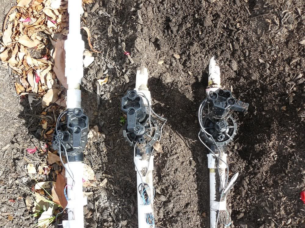
This diagram shows how to wire a rain sensor device. The solenoid has two wires connected to its internal coil. Use wire nuts to make the connections and verify they are secure. This is most commonly a white colored wire. Applying 24vac on the two wires energizes the coil, and causes the rod to contract into the solenoid.
 Source: virginbores.com.au
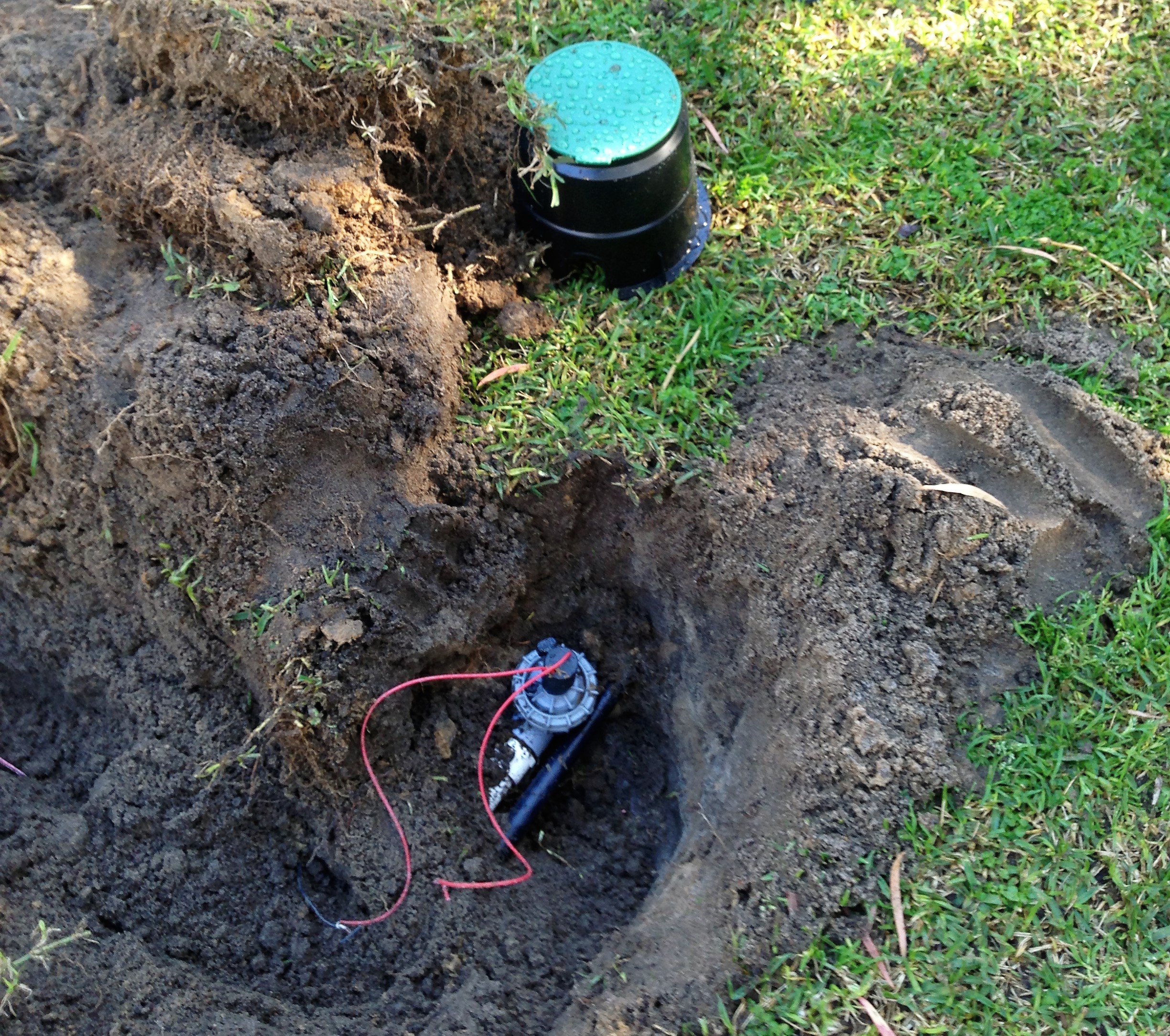
Wiring sensors is quite simple. Applying 24vac on the two wires energizes the coil, and causes the rod to contract into the solenoid. When a solenoid is turned on via the reticulation controller the master solenoid also turns on sending the water down the main supply pipe to the appropriate solenoid which in turn, passes it through itself to the. So when you set your controller make note of which function you are operating in the dial and just set the one start time. Use wire nuts to make the connections and verify they are secure.
 Source: virginbores.com.au
6 tape and screw your first thread join to the pressure point 6 tape and screw your first thread join to the pressure point Place your common wire onto the common terminal. Install pump start relay cover plate and four screws. When a solenoid is turned on via the reticulation controller the master solenoid also turns on sending the water down the main supply pipe to the appropriate solenoid which in turn, passes it through itself to the.

This can scratch the nozzle. When a solenoid is turned on via the reticulation controller the master solenoid also turns on sending the water down the main supply pipe to the appropriate solenoid which in turn, passes it through itself to the. If using an idrate transformer, install it by removing the mounting bracket and installing the transformer as shown below. This can scratch the nozzle. The piping to all the other solenoids is then attached to the other end of the master solenoid and runs to all the solenoid valves.
 Source: virginbores.com.au
Alternatively, we have some additional links that also may help. Close and lock the cabinet door. Have an irrigation question or problem? Route wire through the conduit or one of the openings on the bottom of the cabinet. One group or manifold for the front yard and one for the back.
 Source: youtube.com
(rain check) *this splice should be between the controller. Normally these will be on the same side of the property as the water meter. Most perth retic systems have the solenoid valves in groups. Attach a separate control wire to the remaining wire of each valve. Often people get ‘start times’ and ‘run times’ mixed up.
 Source: youtube.com
Wiring sensors is quite simple. At the solenoid valves, pull back the outer sheathing exposing the individual wires. At the master valve, attach the common wire to either solenoid wire of the valve. Check all connections to ensure they are wired correctly and are secure. One of them is that the fault with your car starter could be some issues with the terminals or the wires that connect your solenoid.
 Source: virginbores.com.au
Applying 24vac on the two wires energizes the coil, and causes the rod to contract into the solenoid. Place your common wire onto the common terminal. It comes with the spring in the “a. These starters come in different sizes depending on the model of your vehicle. Mike briley from access irrigation demonstrates how to wire a 24v irrigation solenoid valve into a mains powered irrigation watering controller using low vol.
 Source: inherentlyromantic.blogspot.com
Try touching the common wire to the left terminal while you touch the vavle wire to the right one as you did before. Often people get ‘start times’ and ‘run times’ mixed up. This is most commonly a white colored wire. Every irrigation has a common wire that connects all of the solenoids together and in most cases it is a black wire, as this is the colour most commonly used. The mainline of a retic system is the pipes that go downstream from the now disconnected master solenoid valve near the water meter all the way to any of the individual solenoid valves that operate any of the stations (zones).
 Source: virginbores.com.au
The piping to all the other solenoids is then attached to the other end of the master solenoid and runs to all the solenoid valves. Put the joiner onto the pvc pipe and screw the solenoid onto the joiner. All wire connections should be done using waterproof connectors. One of them is that the fault with your car starter could be some issues with the terminals or the wires that connect your solenoid. This completes the dry run of the piping.
This site is an open community for users to share their favorite wallpapers on the internet, all images or pictures in this website are for personal wallpaper use only, it is stricly prohibited to use this wallpaper for commercial purposes, if you are the author and find this image is shared without your permission, please kindly raise a DMCA report to Us.
If you find this site beneficial, please support us by sharing this posts to your preference social media accounts like Facebook, Instagram and so on or you can also bookmark this blog page with the title retic solenoid wiring diagram by using Ctrl + D for devices a laptop with a Windows operating system or Command + D for laptops with an Apple operating system. If you use a smartphone, you can also use the drawer menu of the browser you are using. Whether it’s a Windows, Mac, iOS or Android operating system, you will still be able to bookmark this website.
Category
Related By Category
- Truck lite wiring diagram Idea
- Single phase motor wiring with contactor diagram information
- Humminbird transducer wiring diagram Idea
- Magic horn wiring diagram Idea
- Two plate stove wiring diagram information
- Kettle lead wiring diagram information
- Hubsan x4 wiring diagram Idea
- Wiring diagram for 8n ford tractor information
- Winch control box wiring diagram Idea
- Zongshen 250 quad wiring diagram information