Relay panel wiring diagram information
Home » Trending » Relay panel wiring diagram information
Your Relay panel wiring diagram images are available. Relay panel wiring diagram are a topic that is being searched for and liked by netizens today. You can Find and Download the Relay panel wiring diagram files here. Download all royalty-free photos and vectors.
If you’re searching for relay panel wiring diagram pictures information connected with to the relay panel wiring diagram topic, you have visit the right site. Our website frequently provides you with hints for seeing the highest quality video and image content, please kindly search and locate more informative video content and images that match your interests.
Relay Panel Wiring Diagram. Fuse box template wiring diagram sheet inside breaker box label template 10 professional templates ideas 10 professio label templates fuse box fuse panel. Wiring diagram comes with a number of easy to follow wiring diagram guidelines. They permit a small circuit to control a far ahead flow circuit using an electromagnet to rule the flow of electricity inside the circuit. 80 amp automotive relay control panel mgi speedware.
 Plc Panel Wiring Diagram, http//bookingritzcarlton.info From pinterest.com
From the functional devices website you can download rib relays data sheets wiring diagrams autocad drawings and visio drawings all in one place. E300 overload relay wiring diagram wiring view and schematics diagram from www.wiringview.co. Spst 0 30vdc 100a dc solid state relay. It really is meant to assist all the common person in creating a correct system. Electrical wiring installation photovoltaic photovoltaic cell pv solar & pv cell solar panel solar panel installation. The electrical wiring diagram above contains an example of a safety circuit one may find in an industrial environment.
The purpose is to explain different solutions to this design problem good and bad.
Wiring diagram book a1 15 b1 b2 16 18 b3 a2 b1 b3 15 supply voltage 16 18 l m h 2 levels b2 l1 f u 1 460 v f u 2 l2 l3 gnd h1 h3 h2 h4 f u 3 x1a f u. Dual headlamp relay wiring diagram. 12v fuse panel wiring diagram. An example of a wiring diagram for a motor controller is shown in figure 1. Relay and contactor wiring diagram.single pole contactor relay wiring diagram 240v single pole means that it can only control a single circuit and single throw means that there are only two positions the switch can be in one on and one off state mechanical relays do not the esd5 series is an accurate solid state delayed interval timer it offers a 1a steady 10a inrush. Spst 0 30vdc 100a dc solid state relay.
 Source: pinterest.com.au
Diagram 40 amp relay wiring diagram full version hd quality wiring diagram diagramland andreapendibene it. There are different kinds of relays for different purposes. Freightliner truck fl60 wiring diagram free picture freightliner trucks sterling trucks freightliner Conventions parameter names are shown in italic typeface. The three phases are then connected to a power interrupter.
 Source: pinterest.com
12v fuse panel wiring diagram. Print the electrical wiring diagram off in. It is not isolated by using the 12v panel switch. They permit a small circuit to control a far ahead flow circuit using an electromagnet to rule the flow of electricity inside the circuit. The following components are shown here:
 Source: wholefoodsonabudget.com
Relay and contactor wiring diagram. Wiring diagram contactor and overload wiring diagram technic contactor relay wiring wiring diagram datasource. Dashed lines indicate a single purchased component. Overload relay 1ct m m motor 3ct to 120 v separate control * ot is a switch that opens when an overtemperature condition exists (type mfo and mgo only) t1 t3 motor 3 2 l2 t2 l3 t3 t2. Electrical wiring installation photovoltaic photovoltaic cell pv solar & pv cell solar panel solar panel installation.
![[View 21+] Nlight Relay Panel Wiring Diagram [View 21+] Nlight Relay Panel Wiring Diagram](https://ezgiresortotel.netlify.app/img/placeholder.svg)
E300 overload relay wiring diagram wiring view and schematics diagram from www.wiringview.co. The three phases are then connected to a power interrupter. The msr304 is an allen bradley safety relay. Wiring diagram for 5 pin relay 5 pin relay wiring diagram. † e3 plus overload relay when features and/or functions apply specifically to it.
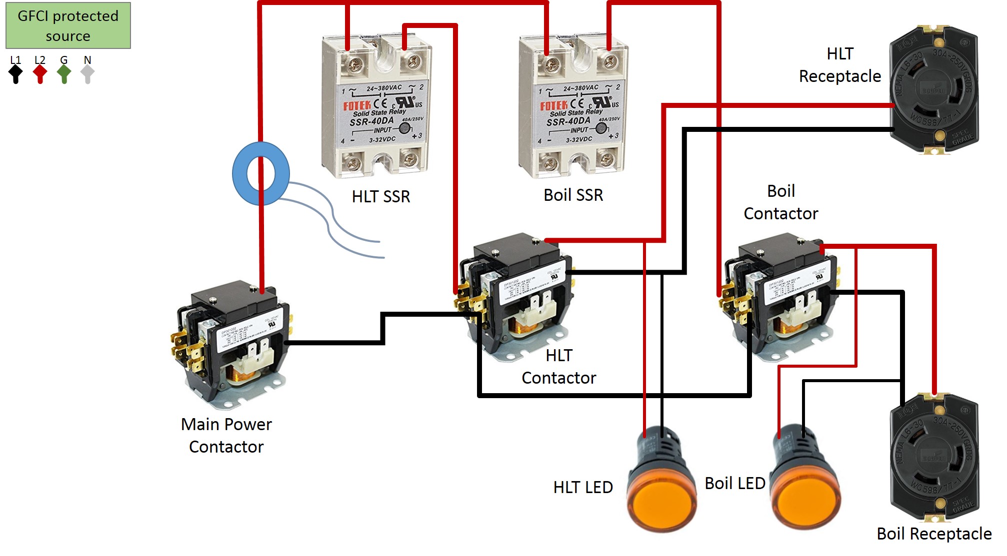
 Source: homebrewtalk.com
Basics 19 instrument loop diagram. An example of a wiring diagram for a motor controller is shown in figure 1. It really is meant to assist all the common person in creating a correct system. These directions will be easy to understand and implement. The diagram above is the 5 pin relay wiring diagram.
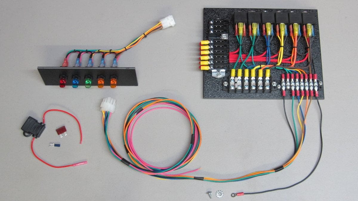
 Source: mgispeedware.com
12v relay wiring diagram 5 pin relay fuse box diagram. The starter relay is another switch that is used to control the starting circuit. If the coil is not activated, 30 will always be connected to 87a. Sample wiring diagrams for a normally open relay example 1. Dashed lines indicate a single purchased component.
 Source: jeepforum.com
The starter relay is another switch that is used to control the starting circuit. Print the electrical wiring diagram off in. Fuse box template wiring diagram sheet inside breaker box label template 10 professional templates ideas 10 professio label templates fuse box fuse panel. Pdf lightsync dmx driver (wd0611) wiring diagrams : An example of a wiring diagram for a motor controller is shown in figure 1.
 Source: mgispeedware.com
Basics 19 instrument loop diagram. Overload relay 1ct m m motor 3ct to 120 v separate control * ot is a switch that opens when an overtemperature condition exists (type mfo and mgo only) t1 t3 motor 3 2 l2 t2 l3 t3 t2. 5 pin is compromised of 3 main. Sample wiring diagrams for a normally open relay example 1. 10x relays and 10x relay socket 4 wire 15cm.
 Source: tops-stars.com
A wiring diagram is a simplified standard photographic depiction of an electrical circuit. These lines far exceed the 120 volts ac standard in most homes. The following components are shown here: The wiring diagram is given below to help you wire it properly. From the functional devices website you can download rib relays data sheets wiring diagrams autocad drawings and visio drawings all in one place.
 Source: ceautoelectricsupply.com
They permit a small circuit to control a far ahead flow circuit using an electromagnet to rule the flow of electricity inside the circuit. If the coil is not activated, 30 will always be connected to 87a. It is not isolated by using the 12v panel switch. Print the electrical wiring diagram off in. These lines far exceed the 120 volts ac standard in most homes.
 Source: izni-radz.blogspot.com
Electrical diagrams chevy only page 2 (with images. Dual headlamp relay wiring diagram. The msr304 is an allen bradley safety relay. Overload relay 1ct m m motor 3ct to 120 v separate control * ot is a switch that opens when an overtemperature condition exists (type mfo and mgo only) t1 t3 motor 3 2 l2 t2 l3 t3 t2. Identify the terminal block and relay numbering for the do signal as per instrument wiring interconnection drawing and electrical schematic wiring drawing.
 Source: pinterest.com
Basic car 3040 amp relay. Wiring diagram for 5 pin relay 5 pin relay wiring diagram. Wiring diagram comes with a number of easy to follow wiring diagram guidelines. These lines far exceed the 120 volts ac standard in most homes. Relay can be the best option to control electrical devices automatically.
 Source: mgispeedware.com
Variety of rib relay in a box wiring diagram. Sample wiring diagrams for a normally open relay example 1. The diagram above is the 5 pin relay wiring diagram. They permit a small circuit to control a far ahead flow circuit using an electromagnet to rule the flow of electricity inside the circuit. (see the lighting diagram below.) tip:
Source: hearth.com
Note that symbols are discussed in detail later). Fuse box template wiring diagram sheet inside breaker box label template 10 professional templates ideas 10 professio label templates fuse box fuse panel. These tags can be found in the panel as well. Relay and contactor wiring diagram.single pole contactor relay wiring diagram 240v single pole means that it can only control a single circuit and single throw means that there are only two positions the switch can be in one on and one off state mechanical relays do not the esd5 series is an accurate solid state delayed interval timer it offers a 1a steady 10a inrush. The following components are shown here:
 Source: pinterest.com.au
5 pin is compromised of 3 main. Variety of rib relay in a box wiring diagram. We have actually accumulated lots of pictures ideally this picture works for you as well as assist you in discovering the response you are seeking. Expanded description of l&g’s em1210 to include the amj. If the coil is not activated, 30 will always be connected to 87a.
 Source: mgispeedware.com
This system uses 3 phase ac power (l1, l2 and l3) connected to the terminals. Sample wiring diagrams for a normally open relay example 1. Electrical wiring installation photovoltaic photovoltaic cell pv solar & pv cell solar panel solar panel installation. They permit a small circuit to control a far ahead flow circuit using an electromagnet to rule the flow of electricity inside the circuit. Dual headlamp relay wiring diagram.
![[View 21+] Nlight Relay Panel Wiring Diagram [View 21+] Nlight Relay Panel Wiring Diagram](https://img.acuitybrands.com/public-assets/catalog/664533/arp-nlt-enclosure-right-facing-interior.jpg?abl_version=08%2F10%2F2020+19:57:06) Source: image379.blogspot.com
Source: image379.blogspot.com
Here is a picture gallery about 12v relay switch wiring diagram complete with the description of the. 4 pin (normally open) relay with the switch on the positive side of the control circuit. These directions will be easy to understand and implement. Expanded description of l&g’s em1210 to include the amj. (see the lighting diagram below.) tip:

Relay and contactor wiring diagram.single pole contactor relay wiring diagram 240v single pole means that it can only control a single circuit and single throw means that there are only two positions the switch can be in one on and one off state mechanical relays do not the esd5 series is an accurate solid state delayed interval timer it offers a 1a steady 10a inrush. Basics 19 instrument loop diagram. E300 overload relay wiring diagram wiring view and schematics diagram from www.wiringview.co. Expanded description of l&g’s em1210 to include the amj. Power windows toyota camry se 2007 system wiring diagrams for cars.
This site is an open community for users to do sharing their favorite wallpapers on the internet, all images or pictures in this website are for personal wallpaper use only, it is stricly prohibited to use this wallpaper for commercial purposes, if you are the author and find this image is shared without your permission, please kindly raise a DMCA report to Us.
If you find this site serviceableness, please support us by sharing this posts to your own social media accounts like Facebook, Instagram and so on or you can also bookmark this blog page with the title relay panel wiring diagram by using Ctrl + D for devices a laptop with a Windows operating system or Command + D for laptops with an Apple operating system. If you use a smartphone, you can also use the drawer menu of the browser you are using. Whether it’s a Windows, Mac, iOS or Android operating system, you will still be able to bookmark this website.
Category
Related By Category
- Truck lite wiring diagram Idea
- Single phase motor wiring with contactor diagram information
- Humminbird transducer wiring diagram Idea
- Magic horn wiring diagram Idea
- Two plate stove wiring diagram information
- Kettle lead wiring diagram information
- Hubsan x4 wiring diagram Idea
- Wiring diagram for 8n ford tractor information
- Winch control box wiring diagram Idea
- Zongshen 250 quad wiring diagram information