Rectifier diagram wiring Idea
Home » Trend » Rectifier diagram wiring Idea
Your Rectifier diagram wiring images are available in this site. Rectifier diagram wiring are a topic that is being searched for and liked by netizens today. You can Find and Download the Rectifier diagram wiring files here. Find and Download all free photos.
If you’re searching for rectifier diagram wiring pictures information connected with to the rectifier diagram wiring interest, you have come to the right site. Our site always provides you with suggestions for viewing the maximum quality video and image content, please kindly search and find more enlightening video articles and images that match your interests.
Rectifier Diagram Wiring. 11 full wave bridge rectifier diagram. Studying the wiring diagram a bit more, i can see that elec start sleds. Each component ought to be set and linked to different parts in particular manner. Sample motorcycle wiring diagram included in this shipment and dictionary of automotive terms a teacherweb.
 Fast Active Rectifier Circuit Diagram From circuit-diagramz.com
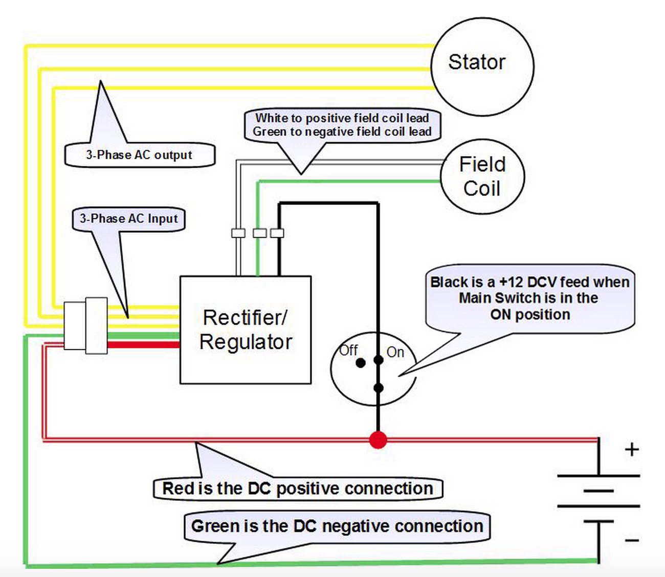
5 pin rectifier wiring diagram wiring diagram is a simplified agreeable pictorial representation of an electrical circuit it shows the components of the circuit as simplified shapes and the. Motorcycle regulator rectifier wiring diagram. Don t miss our motorcycle regulator rectifier data library. Battery positive cable voltage sensing wire and ignition wire. In the manner of grating to remove, replace or repair the wiring in an automobile, having an accurate and detailed 5 wire regulator rectifier. Puch wiring mopedwiki motorcycle wiring puch electrical diagram.
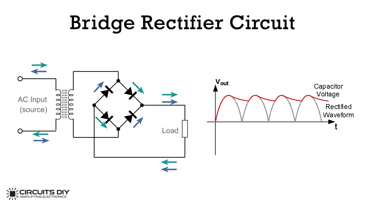
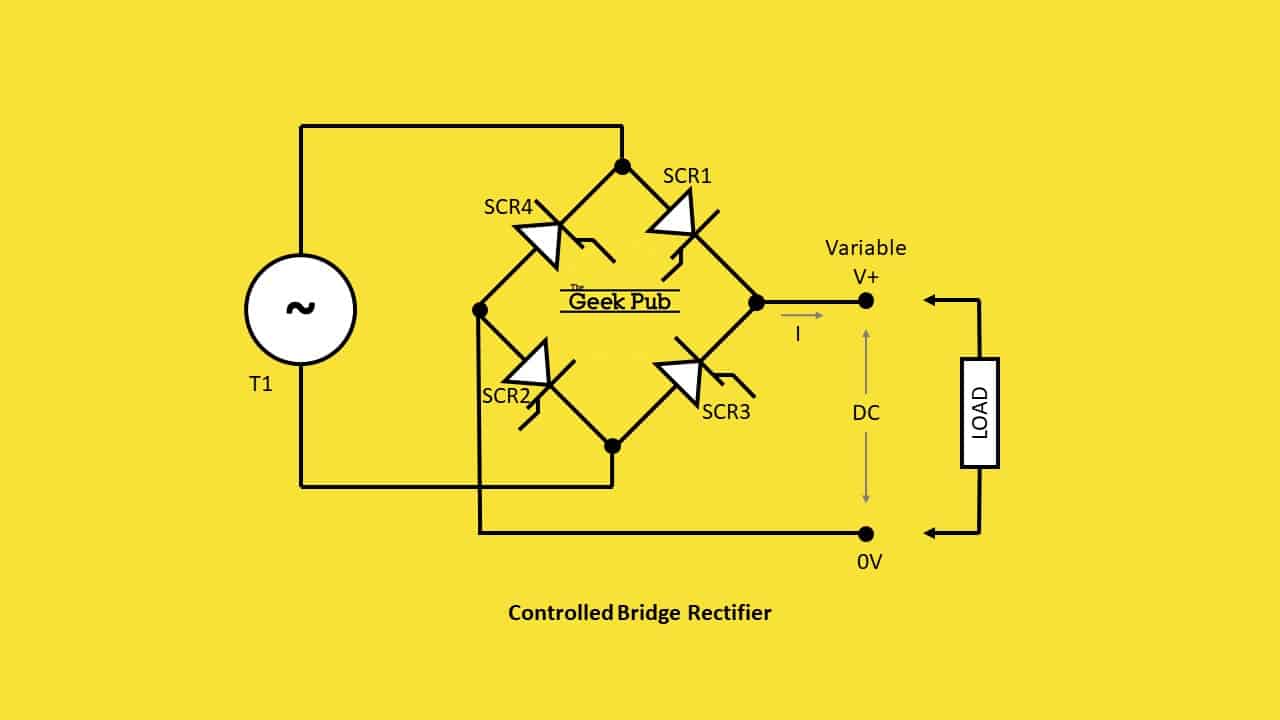
Bridge rectifiers are used to convert alternating current (ac) to direct current (dc).
However, it doesn’t mean link between the cables. Chinese 5 wire 1 plug voltage regulator rectifier for gy6 50cc 125cc 150cc scooters atvs. 4 pin rectifier wiring diagram. A wiring diagram is a schematic type that uses abstract illustrated symbols to show all of the components of a system. 5 pin rectifier wiring diagram. The kbpc5010 is one massive bridge rectifier.
 Source: circuit-diagramz.com
Part of lamberts bikes online library of pdf motorcycle manuals wiring diagrams and technical guides. Voltage regulator voltage regulator rectifier fit for gy6 125cc 150cc 6. Bridge rectifiers are used to convert alternating current (ac) to direct current (dc). By lynwood nastasia | june 26, 2021. Figure 1 shows such a bridge rectifier composed of four diodes d 1 d 2 d 3 and d 4 in which the input is supplied across two terminals a and b in the figure while the output is collected across the load resistor r l connected between the terminals c and d.
 Source: schematron.org
We know the 3 yellow are aligned together under the other 2. This is designed to plug into the stock wiring harness. The rectifier which consists of four diodes and are connected in the form of bridge is called as a bridge rectifier. Wiring diagram consists of numerous comprehensive illustrations that show the link of varied things. 5 pin rectifier wiring diagram wiring diagram is a simplified agreeable pictorial representation of an electrical circuit it shows the components of the circuit as simplified shapes and the.
 Source: circuits-diy.com
Following diagrams is fairly simple, but making use of it inside the scope of how the device operates is a new different matter. The best advice is not necessarily only look from the diagram, yet understand how the components operate when in use. In the manner of grating to remove, replace or repair the wiring in an automobile, having an accurate and detailed 5 wire regulator rectifier. Like all good motorcycle engineers lamberts bikes have produced part specific electrical wiring schematics. Motorcycle regulator rectifier wiring diagram.
 Source: engineersgarage.com
5 pin rectifier wiring diagram wiring diagram is a simplified agreeable pictorial representation of an electrical circuit it shows the components of the circuit as simplified shapes and the. Tvs apache wiring diagram dolgular com at in tvs apache wiring diagram house wiring electrical panel wiring electrical panel. Simply plug the connector onto the 5 pins row and make sure that the pin assignments and wire assignments are matched correctly. 2 phase 5 wire motorcycle regulator rectifier wiring diagram pdf. Occasionally, the cables will cross.
 Source: circuit-diagramz.com
Battery positive cable voltage sensing wire and ignition wire. 1980 vespa p200 witth a battery wiring diagram modern vespa. Motorcycle regulator rectifier wiring diagram. Wiring diagram 4 pin regulator rectifier wiring diagram by vallery masson on april 26, 2021 many rick s motorsport electrics rectifier regulators eliminate what is commonly referred to as a signal wire on oe pieces. The red wire from the rr connects to the red wire in the wiring harness.
 Source: dentistmitcham.com
M 3 2 2 2 phase 5 wire. They are constructed from at least 4 diodes and are a major component of most basic ac. Simply plug the connector onto the 5 pins row and make sure that the pin assignments and wire assignments are matched correctly. The red wire from the rr connects to the red wire in the wiring harness. 5 pin rectifier regulator wiring diagram.
 Source: wiringforums.com
There’ll be principal lines which are represented by l1, l2, l3, and so on. Don t miss our motorcycle regulator rectifier data library. The suffering in reality is that every car is different. As stated earlier, the lines at a rectifier regulator wiring diagram signifies wires. قاعدة البيانات تسويق تفهم 6 pin voltage regulator wiring diagram mauketivi net.
 Source: thegeekpub.com
It contains instructions and diagrams for different kinds of wiring strategies as well as other things like lights, windows, and so on. 4 pin rectifier wiring diagram. As stated earlier the lines at a rectifier regulator wiring diagram signifies wires. Mercury mariner 6 wire 815279 3 universal 12 volt regulator rectifier wiring new to indiana 650 voltage upgrade 815279t bdx 8 and 11 pole stator installation 883072t for suitable wires pin help why are there six on my diy ribnet forums motorcycle tester b6200hst needed diagram rick s phase 12v. This is the ultimate guide to the humble motorcycle regulator rectifier.
 Source: dentistmitcham.com
5 pin rectifier wiring diagram. Each diagram includes the part and associated parts all in one wiring diagram. Provided below is an online pdf document for lamberts bikes 3 phase 6 wire regulator rectifier wiring diagram. Following diagrams is fairly simple, but making use of it inside the scope of how the device operates is a new different matter. However, it doesn’t mean link between the cables.
 Source: untpikapps.com
Voltage regulator voltage regulator rectifier fit for gy6 125cc 150cc 6. Puch wiring mopedwiki motorcycle wiring puch electrical diagram. Provided below is an online pdf document for lamberts bikes 3 phase 6 wire regulator rectifier wiring diagram. قاعدة البيانات تسويق تفهم 6 pin voltage regulator wiring diagram mauketivi net. The red wire from the rr connects to the red wire in the wiring harness.
 Source: diyaudio.com
The kbpc5010 is one massive bridge rectifier. 5 pin regulator rectifier wiring diagram august 15, 2021. By facybulka posted on august 5, 2018 114 views. By lynwood nastasia | june 26, 2021. Puch wiring mopedwiki motorcycle wiring puch electrical diagram.
Source: forums.windynation.com
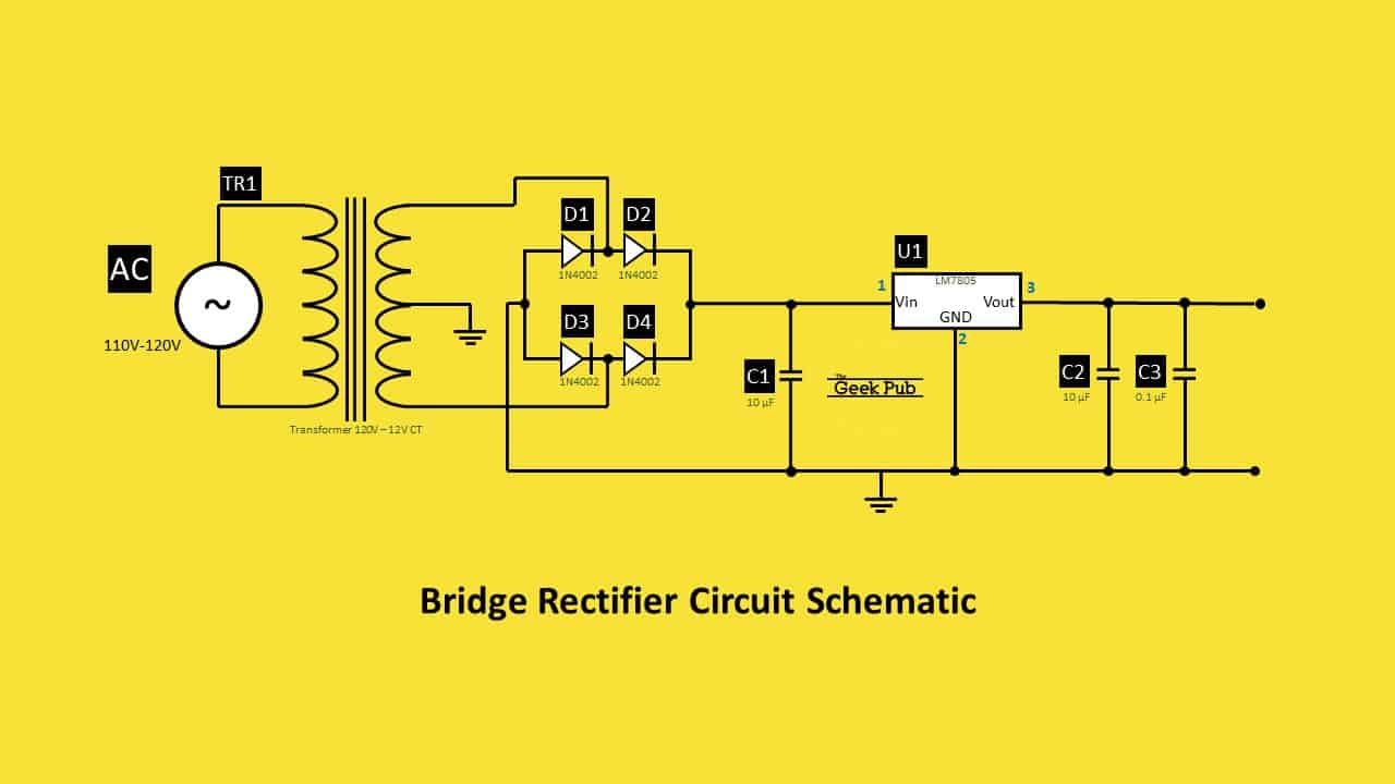
Battery positive cable voltage sensing wire and ignition wire. Sample motorcycle wiring diagram included in this shipment and dictionary of automotive terms a teacherweb. Provided below is an online pdf document for lamberts bikes 3 phase 6 wire regulator rectifier wiring diagram. Ripple factor in a bridge rectifier is half than that of a half wave rectifier. Here are a couple of photos of the carter 150cc gy6 rectifier.
 Source: thegeekpub.com
A filtration capacitor can be used for smooth output. This is the ultimate guide to the humble motorcycle regulator rectifier. It contains instructions and diagrams for different kinds of wiring strategies as well as other things like lights, windows, and so on. Here are a couple of photos of the carter 150cc gy6 rectifier. 2 phase 5 wire motorcycle regulator rectifier wiring diagram pdf.
 Source: diyaudio.com
Similar to frustrating to remove, replace or repair the wiring in an automobile, having an accurate and detailed 6 wire regulator. 2 phase 5 wire motorcycle regulator rectifier wiring diagram pdf. 5 pin regulator rectifier wiring diagram august 15, 2021. The kbpc5010 is one massive bridge rectifier. Wiring diagram consists of numerous comprehensive illustrations that show the link of varied things.
 Source: schematron.org
Adding a regulator rectifier to an outboard motor so you can charge a battery is a relatively simple job. Each diagram includes the part and associated parts all in one wiring diagram. The red wire from the rr connects to the red wire in the wiring harness. 11 full wave bridge rectifier diagram. Ripple factor in a bridge rectifier.
 Source: wiringall.com
It contains instructions and diagrams for different kinds of wiring strategies as well as other things like lights, windows, and so on. Provided below is an online pdf document for lamberts bikes 3 phase 6 wire regulator rectifier wiring diagram. Simply plug the connector onto the 5 pins row and make sure that the pin assignments and wire assignments are matched correctly. Following diagrams is fairly simple, but making use of it inside the scope of how the device operates is a new different matter. Chinese voltage regulator wired up to honda gx clone with charge coils.
 Source: britishmotorcycleparts.co.nz
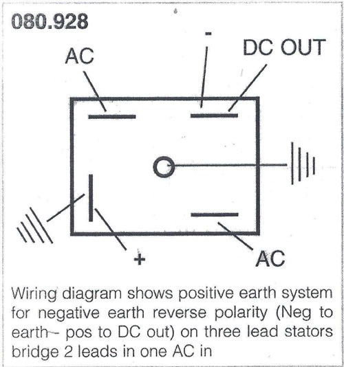
5 pin rectifier wiring diagram wiring diagram is a simplified agreeable pictorial representation of an electrical circuit it shows the components of the circuit as simplified shapes and the. The 10 100 rectifier plugs into the harness at the same location as the oe rectifier. Mercury mariner 6 wire 815279 3 universal 12 volt regulator rectifier wiring new to indiana 650 voltage upgrade 815279t bdx 8 and 11 pole stator installation 883072t for suitable wires pin help why are there six on my diy ribnet forums motorcycle tester b6200hst needed diagram rick s phase 12v. Therell be principal lines which are represented by l1 l2 l3 and so on. Ripple factor in a bridge rectifier.
 Source: diagramweb.net
Regulator rectifier 7003 rr150 tech support. Each component ought to be set and linked to different parts in particular manner. Simply plug the connector onto the 5 pins row and make sure that the pin assignments and wire assignments are matched correctly. This is designed to plug into the stock wiring harness. Each diagram includes the part and associated parts all in one wiring diagram.
This site is an open community for users to do submittion their favorite wallpapers on the internet, all images or pictures in this website are for personal wallpaper use only, it is stricly prohibited to use this wallpaper for commercial purposes, if you are the author and find this image is shared without your permission, please kindly raise a DMCA report to Us.
If you find this site serviceableness, please support us by sharing this posts to your preference social media accounts like Facebook, Instagram and so on or you can also bookmark this blog page with the title rectifier diagram wiring by using Ctrl + D for devices a laptop with a Windows operating system or Command + D for laptops with an Apple operating system. If you use a smartphone, you can also use the drawer menu of the browser you are using. Whether it’s a Windows, Mac, iOS or Android operating system, you will still be able to bookmark this website.
Category
Related By Category
- Predator 670 engine wiring diagram Idea
- Frsky x8r wiring diagram information
- Pioneer ts wx130da wiring diagram Idea
- Johnson 50 hp wiring diagram Idea
- Kohler voltage regulator wiring diagram Idea
- Johnson 50 hp outboard wiring diagram information
- Kti hydraulic remote wiring diagram Idea
- Pyle plpw12d wiring diagram information
- Tx9600ts wiring diagram information
- Lifan 50cc wiring diagram information