Racing drone wiring diagram information
Home » Trending » Racing drone wiring diagram information
Your Racing drone wiring diagram images are available in this site. Racing drone wiring diagram are a topic that is being searched for and liked by netizens today. You can Get the Racing drone wiring diagram files here. Get all free photos.
If you’re looking for racing drone wiring diagram pictures information connected with to the racing drone wiring diagram keyword, you have visit the right site. Our website frequently gives you hints for refferencing the maximum quality video and image content, please kindly hunt and locate more enlightening video content and graphics that match your interests.
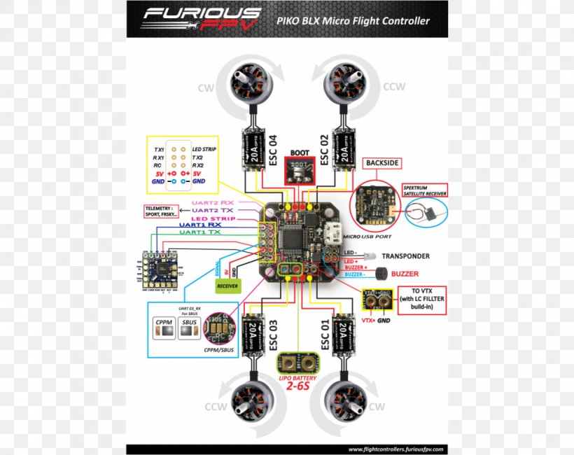
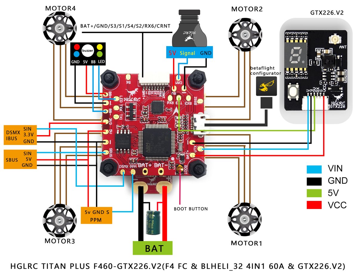
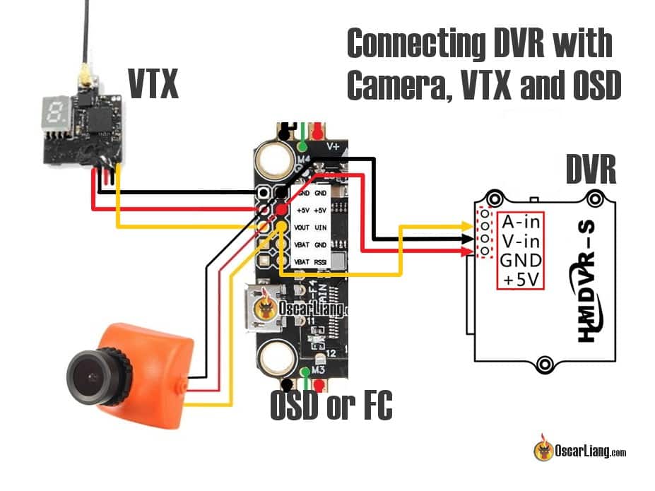
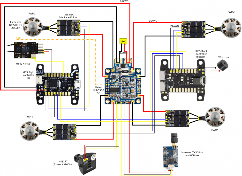
Racing Drone Wiring Diagram. I’ve searched the web for any clues, but can’t find the answer. Eachine aurora 90 mini fpv racer spare part v1.1 spacer blocks 4 pieces. The diagram above shows a schematic of the quad and will hopefully aid through the building process. Darwinfpv stack for fpv drone racing and freestyle sold by pyrodrone.
 AeroQuadUVicWiring.png 937×1,037 pixeles Ingenieria From pinterest.com.mx
Omnibusf4fw (in betaflight) / fireworks v2 (in inav). Previous article quadcopter wiring diagram guide. 08025 brushless motor with durable ball bearing for increase flight and low maintenance durable polypropylene plastic frame with propeller guards. 5.if you like to make this board work with other radio transmitter,please check our. Naze32 wiring setup with bec 5v drone drones concept drone design. Wiring diagram.connection diagram) i hope there’s a connection diagram for this flight controller related products.
The battery wire should be the thickest fpv drone wire as it handles up to or over 150a of current.
4 × 3 pin esc pin layout. 25.5*25.5mm/φ3mm, with micro usb connector; Wiring diagram drone racing simulator quadcopter is an android education app developed by aduhai wallpaper and published on the google play store. Before wiring up your camera and video. Make sure to set the drone on a flat surface and make it face away from you, again very important. Your assembled racing drone frame (see part 2 of this series).
 Source: favpng.com
4 × 3 pin esc pin layout. Drone wiring diagram very detailed to show you that how to connect them. The team black sheep crossfire nano rx is the best most versatile option, it�s capable of flying nearly 10 miles away in some cases and has the power to penetrate Flight controller connection wiring diagram; Naze32 wiring setup with bec 5v drone drones concept drone design.
 Source: circuitdiagramimages.blogspot.com
The xsr has 5 wires, one being a white wire. 4 × 3 pin esc pin layout. Now connect the drone to the usb and betaflight like before and stay on the first page that opens which is the one showing a drone model. This is the central hub from which booms radiate like spokes on a wheel. Rekon3 fpv racing drone manual package included hglrc rekon3 fpv racing drone1 accessory package1 product specifications product parameters model rekon3 vtx fpv racing drone frame kit rekon3 frame kit flight controller zeus5 aio flight controller vtx zeus nano 350mw motor 1202.5 motor 1s kv11600 support neceiver sbus.dsmx.crsf input voltage.
 Source: pinterest.com
Make sure to set the drone on a flat surface and make it face away from you, again very important. This article explains how to connect the escs, motors and propellers for pixhawk and use the diagram for your frame type, and wire the motors as shown. The team black sheep crossfire nano rx is the best most versatile option, it�s capable of flying nearly 10 miles away in some cases and has the power to penetrate Flight controller connection wiring diagram; Racerstar 20a 4in1 wiring diagram.
 Source: oscarliang.com
4 × 3 pin esc pin layout. Previous article quadcopter wiring diagram guide. Cg02 gb 3axis brushless camera/ gimbal. Flight controller connection wiring diagram; Find your tinyhawk after a crash.
 Source: rcdronegood.com
Wiring diagram.connection diagram) i hope there’s a connection diagram for this flight controller related products. Before wiring up your camera and video. Make sure to set the drone on a flat surface and make it face away from you, again very important. We can split the base drone wiring diagram into multiple parts as below: Your assembled racing drone frame (see part 2 of this series).
 Source: myfpvstore.com
We are experts at drones for all professional and consumer applications. Before we start, it is good to layout the components to make sure that there is enough space for them in the chassis. Drone wiring diagram very detailed to show you that how to connect them. 25.5*25.5mm/φ3mm, with micro usb connector; Circuit diagram of drone with arduino.
 Source: rcdronegood.com
It houses battery, main boards, processors avionics, cameras, and sensors. The xsr has 5 wires, one being a white wire. Omnibusf4fw (in betaflight) / fireworks v2 (in inav). In this article, you will need the following parts: By electrcsh33p colibri race powercube flight controller replacement by jeff qq190 tank v3 racing drone frame kit set includes motors, plastics, and camera.
 Source: schematron.org
Flight controller connection wiring diagram; Phantom 3 standard gimbal wiring diagram. The recommended motor fpv wire size is 20awg to 18awg. By electrcsh33p colibri race powercube flight controller replacement by jeff qq190 tank v3 racing drone frame kit set includes motors, plastics, and camera. Flight controller connection wiring diagram;
 Source: circuitdiagramimages.blogspot.com
Simply connects the vifly finder 2 to your flight controller (racing drone) or receiver (rc airplane) via 3 wires, and it’s ready to enjoy your flight. The diagram above shows a schematic of the quad and will hopefully aid through the building process. Eachine aurora 90 mini fpv racer spare part v1.1 spacer blocks 4 pieces. Dji phantom 3 contains many interesting technical solutions. Posted on may 23, 2017.
 Source: pinterest.com
By electrcsh33p colibri race powercube flight controller replacement by jeff qq190 tank v3 racing drone frame kit set includes motors, plastics, and camera. We can split the base drone wiring diagram into multiple parts as below: Before wiring up your camera and video. Your assembled racing drone frame (see part 2 of this series). The recommended motor fpv wire size is 20awg to 18awg.
 Source: blog.dronetrest.com
The team black sheep crossfire nano rx is the best most versatile option, it�s capable of flying nearly 10 miles away in some cases and has the power to penetrate Your assembled racing drone frame (see part 2 of this series). Wiring diagram.connection diagram) i hope there’s a connection diagram for this flight controller related products. Plug in usb while the drone is facing away. 08025 brushless motor with durable ball bearing for increase flight and low maintenance durable polypropylene plastic frame with propeller guards.
Source: circuitdiagramimages.blogspot.com
Cg02 gb 3axis brushless camera/ gimbal. If you�re not ultra concerned with latency (cough cough. Dronevibes is a community of drones enthusiasts. A 4in1 esc is more convenient to use as there is less messy wiring as the powering of each esc is done internally on the board. A hard landing may not break the body of the drone but the shock could damage.
 Source: flyingtech.co.uk
I’ve searched the web for any clues, but can’t find the answer. 4 × 3 pin esc pin layout. It has gained around 1000 installs so far, with an average rating of 3.0 out of 5 in the play store. 11.03.2019 11.03.2019 2 comments on drone esc wiring diagram. Cg02 gb 3axis brushless camera/ gimbal.
 Source: dronepic.blogspot.com
2.plug and play for dji hd fpv system, no need to solder tiny wires; Flight controller connection wiring diagram; As you see above the base of drone wiring diagram, there are so many components are need to connected with each others. I can get a wiring diagram but t. Connect the esc for motor 1 to the pdb pins marked m1 motor 6s esc to the pins marked m6 etc.
 Source: pinterest.com
It houses battery, main boards, processors avionics, cameras, and sensors. The diagram below is a typical connection for a fpv racing quadcopter. It has gained around 1000 installs so far, with an average rating of 3.0 out of 5 in the play store. Make sure to set the drone on a flat surface and make it face away from you, again very important. Wiring diagram.connection diagram) i hope there’s a connection diagram for this flight controller related products.

The diagram above shows a schematic of the quad and will hopefully aid through the building process. It has gained around 1000 installs so far, with an average rating of 3.0 out of 5 in the play store. Plug in usb while the drone is facing away. In this article, you will need the following parts: If you�re not ultra concerned with latency (cough cough.
 Source: pinterest.com.mx
Find your tinyhawk after a crash. However, i’m confused with the wiring diagram for the omnibus f4 aio and frsky xsr. 11.03.2019 11.03.2019 2 comments on drone esc wiring diagram. The xsr has 5 wires, one being a white wire. Rekon3 fpv racing drone manual package included hglrc rekon3 fpv racing drone1 accessory package1 product specifications product parameters model rekon3 vtx fpv racing drone frame kit rekon3 frame kit flight controller zeus5 aio flight controller vtx zeus nano 350mw motor 1202.5 motor 1s kv11600 support neceiver sbus.dsmx.crsf input voltage.
 Source: pinterest.com
As you see above the base of drone wiring diagram, there are so many components are need to connected with each others. Max tiny hawk 75mm indoor racing stem drone. Rekon3 fpv racing drone manual package included hglrc rekon3 fpv racing drone1 accessory package1 product specifications product parameters model rekon3 vtx fpv racing drone frame kit rekon3 frame kit flight controller zeus5 aio flight controller vtx zeus nano 350mw motor 1202.5 motor 1s kv11600 support neceiver sbus.dsmx.crsf input voltage. Drone wiring diagram very detailed to show you that how to connect them. Connect the esc for motor 1 to the pdb pins marked m1 motor 6 s esc to the pins marked m6 etc.
This site is an open community for users to do sharing their favorite wallpapers on the internet, all images or pictures in this website are for personal wallpaper use only, it is stricly prohibited to use this wallpaper for commercial purposes, if you are the author and find this image is shared without your permission, please kindly raise a DMCA report to Us.
If you find this site beneficial, please support us by sharing this posts to your own social media accounts like Facebook, Instagram and so on or you can also bookmark this blog page with the title racing drone wiring diagram by using Ctrl + D for devices a laptop with a Windows operating system or Command + D for laptops with an Apple operating system. If you use a smartphone, you can also use the drawer menu of the browser you are using. Whether it’s a Windows, Mac, iOS or Android operating system, you will still be able to bookmark this website.
Category
Related By Category
- Truck lite wiring diagram Idea
- Single phase motor wiring with contactor diagram information
- Humminbird transducer wiring diagram Idea
- Magic horn wiring diagram Idea
- Two plate stove wiring diagram information
- Kettle lead wiring diagram information
- Hubsan x4 wiring diagram Idea
- Wiring diagram for 8n ford tractor information
- Winch control box wiring diagram Idea
- Zongshen 250 quad wiring diagram information