Racepak dash wiring diagram information
Home » Trend » Racepak dash wiring diagram information
Your Racepak dash wiring diagram images are available. Racepak dash wiring diagram are a topic that is being searched for and liked by netizens today. You can Download the Racepak dash wiring diagram files here. Download all free vectors.
If you’re looking for racepak dash wiring diagram pictures information related to the racepak dash wiring diagram topic, you have visit the right blog. Our site frequently provides you with suggestions for downloading the highest quality video and image content, please kindly surf and find more enlightening video articles and graphics that match your interests.
Racepak Dash Wiring Diagram. With maddening to remove, replace or fix the wiring in an automobile, having an accurate and detailed gm 4l60e transmission. It reveals the parts of the circuit as streamlined shapes, as well as the power and also signal links in between the devices. You will need to connect the 4 wires from the racepak iq3 dash to the provided 8 pin can connector. Button wiring diagram chassis ground or.
 Racepak Wiring Diagram From diagramweb.net
This cable is connected to the 5 pin vnet port on the rear of the dash. Optimized for the racer who needs to view vital functions quickly and easily, the iq3 display dash can display up to 28 inputs on four pages. It can be used as a standalone unit or. The first wiring diagram states: Button wiring diagram chassis ground or. The replay dash kit includes a wire loom and sensors for engine rpm, water temperature, oil pressure, and battery voltage.
A wiring diagram is a simplified standard photographic representation of an electric circuit.
Sensors for monitoring other function must be purchased as options. A wiring diagram usually gives information virtually the relative viewpoint and concord of devices and. External programming button and fan output wiring diagram. Following infuriating to remove, replace or repair the wiring in an automobile, having an accurate and detailed racepak dash wiring diagram is vital. Racepak llc was founded in 1985 by spencer eisenbarth and ron armstrong, originally as racepak and its parent company, competition systems, incorporated (csi). The replay dash kit includes a wire loom and sensors for engine rpm, water temperature, oil pressure, and battery voltage.
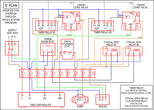 Source: schematron.org
No sensor wiring harness is required. Variety of racepak iq3 wiring diagram. This design provides the ability to transmit all sensor data through a single cable. Connect pc to vsd / sportsman unit with serial cable (9 pin on one end and stereo end on the other. The first wiring diagram states:
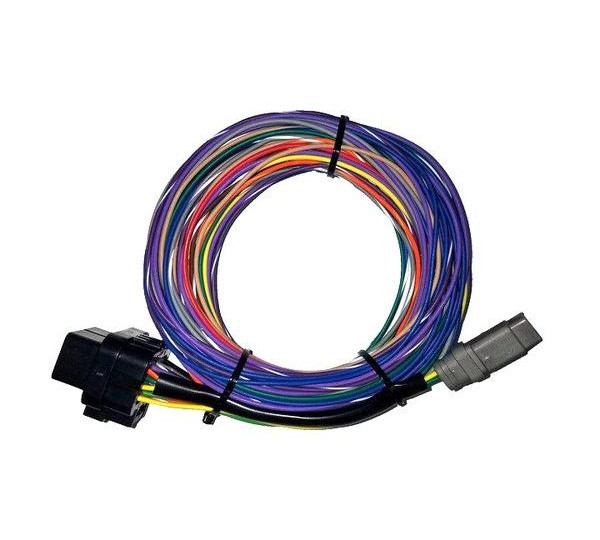 Source: faceitsalon.com
The haltech iq3 street dash is a fully programmable lcd digital display dash that displays information to the user. This warranty is in lieu of any other expressed or implied warranties, including any implied It reveals the parts of the circuit as streamlined shapes, as well as the power and also signal links in between the devices. This design provides the ability to transmit all sensor data through a single cable. Iq3 street dash installation manual iq3 street dash wiring pinout connector pinout description.
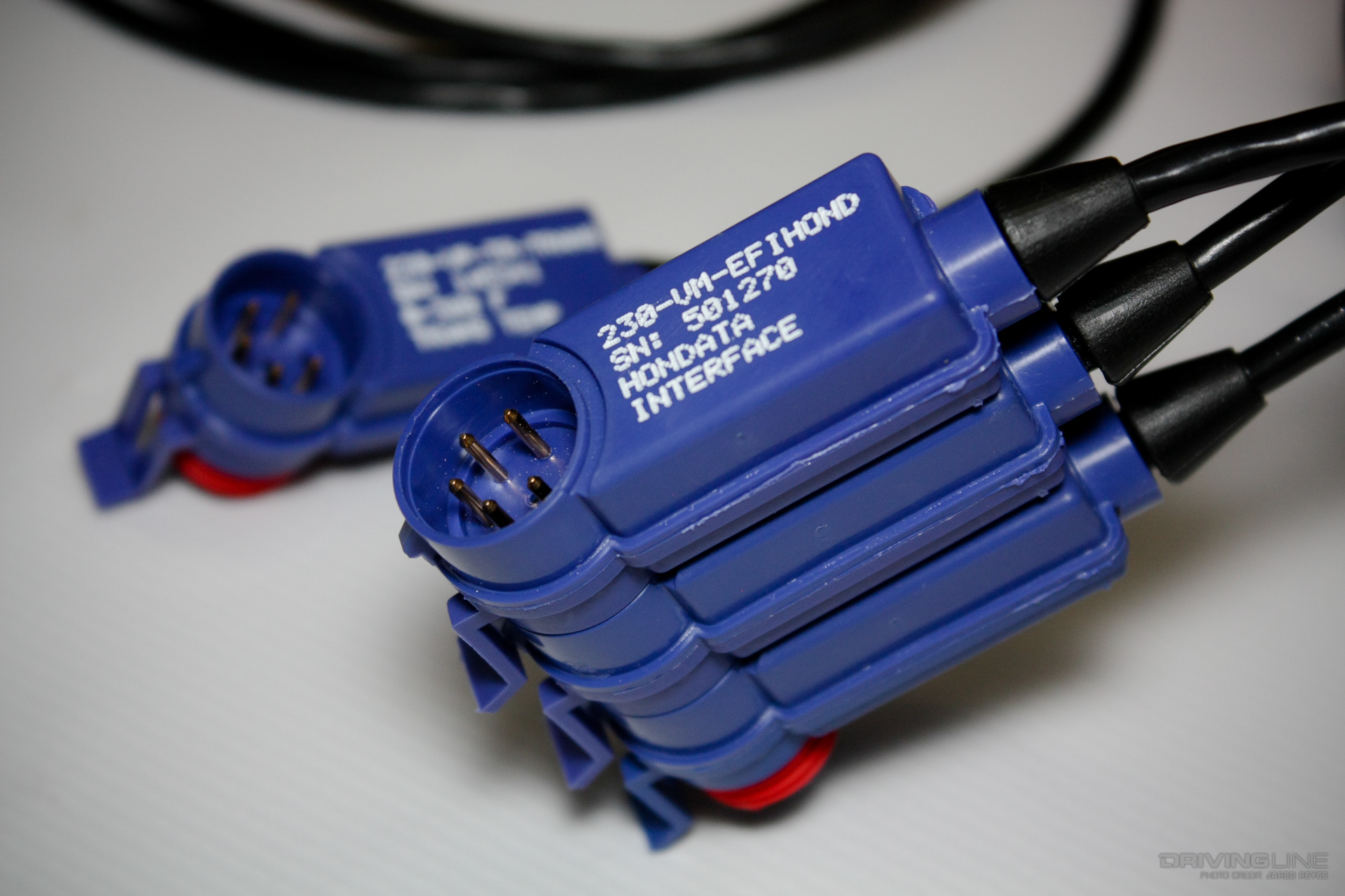 Source: drivingline.com
It reveals the parts of the circuit as streamlined shapes, as well as the power and also signal links in between the devices. Both men were engineers with strong backgrounds in electrical and mechanical applications, and both had an interest in motor sports. The haltech iq3 street dash is a fully programmable lcd digital display dash that displays information to the user. You will need to connect the 4 wires from the racepak iq3 dash to the provided 8 pin can connector. Racepak llc reserves the right to revise this installation and user manual at any time, without obligation to notify any person of revisions.
 Source: ricardolevinsmorales.com
Variety of racepak iq3 wiring diagram. A wiring diagram is a simplified standard photographic representation of an electric circuit. To tim or any iq3/motec ecu user�s, i just recieved my new iq3 logger dash from the states and aswell the motec can bus interface module cable/ v net cable, the paper work that come with the v net cable. Racepak llc reserves the right to revise this installation and user manual at any time, without obligation to notify any person of revisions. Racepak llc is not liable for any errors contained within or for incidental or consequential damages in connection with the supply, performance or use of the hardware and software or this manual.
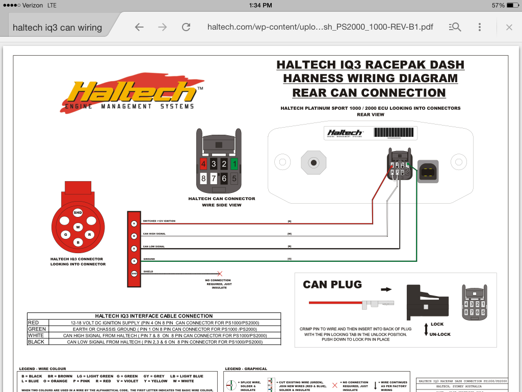 Source: rx7club.com
Quicksilver 3000 control box diagram (1) racepak iq3 display dash wiring diagram (1) racepak iq3 drag dash wiring diagram (1) racepak iq3 wiring diagram (1) saas+boost+gauge+wiring+diagram (1) shunt trip breaker wiring diagram (1) siemens shunt trip breaker wiring diagram (1) speaker wiring diagram ohms (1) tfi wiring diagram ford (1) It shows the components of the circuit as simplified shapes, and the skill and signal links between the devices. A wiring diagram usually gives information virtually the relative viewpoint and concord of devices and. A wiring diagram is a simplified standard photographic representation of an electric circuit. Iq3 street dash installation manual iq3 street dash wiring pinout connector pinout description.
 Source: faceitsalon.com
States to refer to your motec user manual for the can bus connection information. The only factory installed wires in the port a connector are the ones required for power and ground. Sensors for monitoring other function must be purchased as options. The first wiring diagram states: It shows the components of the circuit as simplified shapes, and the skill and signal links between the devices.
 Source: wiringdiagram.2bitboer.com
This connector provides connection to the external program button inputs and external warning or shift light output. All other wires are provided with t he pins crimped and ready to. It shows the components of the circuit as simplified shapes, and the skill and signal links between the devices. Both men were engineers with strong backgrounds in electrical and mechanical applications, and both had an interest in motor sports. Button wiring diagram chassis ground or.
 Source: diyautotune.com
Racepak llc was founded in 1985 by spencer eisenbarth and ron armstrong, originally as racepak and its parent company, competition systems, incorporated (csi). Racepak llc is not liable for any errors contained within or for incidental or consequential damages in connection with the supply, performance or use of the hardware and software or this manual. The only factory installed wires in the port a connector are the ones required for power and ground. Final addition was the racepak iq3 dash to display all the data from the haltech ecu. Vsd firmware v57 ( kb)* for units with version 50 & higher.
 Source: drivingline.com
Quicksilver 3000 control box diagram (1) racepak iq3 display dash wiring diagram (1) racepak iq3 drag dash wiring diagram (1) racepak iq3 wiring diagram (1) saas+boost+gauge+wiring+diagram (1) shunt trip breaker wiring diagram (1) siemens shunt trip breaker wiring diagram (1) speaker wiring diagram ohms (1) tfi wiring diagram ford (1) Racepak llc was founded in 1985 by spencer eisenbarth and ron armstrong, originally as racepak and its parent company, competition systems, incorporated (csi). To tim or any iq3/motec ecu user�s, i just recieved my new iq3 logger dash from the states and aswell the motec can bus interface module cable/ v net cable, the paper work that come with the v net cable. Optimized for the racer who needs to view vital functions quickly and easily, the iq3 display dash can display up to 28 inputs on four pages. This design provides the ability to transmit all sensor data through a single cable.
 Source: ricardolevinsmorales.com
Variety of racepak iq3 wiring diagram. No sensor wiring harness is required. Ultra dash installation 3 port a wiring port a uses the 15 position connector. The haltech iq3 street dash is a fully programmable lcd digital display dash that displays information to the user. All other wires are provided with t he pins crimped and ready to.
 Source: ricardolevinsmorales.com
Quicksilver 3000 control box diagram (1) racepak iq3 display dash wiring diagram (1) racepak iq3 drag dash wiring diagram (1) racepak iq3 wiring diagram (1) saas+boost+gauge+wiring+diagram (1) shunt trip breaker wiring diagram (1) siemens shunt trip breaker wiring diagram (1) speaker wiring diagram ohms (1) tfi wiring diagram ford (1) A wiring diagram is a simplified standard photographic representation of an electric circuit. This cable is connected to the 5 pin vnet port on the rear of the dash. All other wires are provided with t he pins crimped and ready to. The only factory installed wires in the port a connector are the ones required for power and ground.
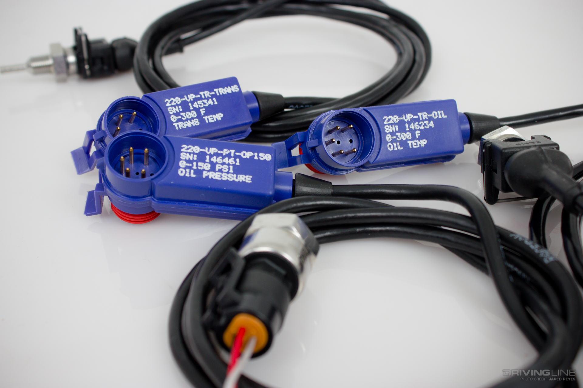 Source: drivingline.com
Through an earlier joint effort aimed at obtaining. Quicksilver 3000 control box diagram (1) racepak iq3 display dash wiring diagram (1) racepak iq3 drag dash wiring diagram (1) racepak iq3 wiring diagram (1) saas+boost+gauge+wiring+diagram (1) shunt trip breaker wiring diagram (1) siemens shunt trip breaker wiring diagram (1) speaker wiring diagram ohms (1) tfi wiring diagram ford (1) Ultra dash installation 3 port a wiring port a uses the 15 position connector. This eliminates the need for an external. Vsd firmware v57 ( kb)* for units with version 50 & higher.
 Source: manualzz.com
The only factory installed wires in the port a connector are the ones required for power and ground. You will need to connect the 4 wires from the racepak iq3 dash to the provided 8 pin can connector. Racepak llc is not liable for any errors contained within or for incidental or consequential damages in connection with the supply, performance or use of the hardware and software or this manual. This design provides the ability to transmit all sensor data through a single cable. The only factory installed wires in the port a connector are the ones required for power and ground.
 Source: diagramweb.net
Racepak llc was founded in 1985 by spencer eisenbarth and ron armstrong, originally as racepak and its parent company, competition systems, incorporated (csi). Vsd firmware v57 ( kb)* for units with version 50 & higher. This warranty is in lieu of any other expressed or implied warranties, including any implied Iq3 street dash installation manual iq3 street dash wiring pinout connector pinout description. No sensor wiring harness is required.
 Source: forums.haltech.com
Through an earlier joint effort aimed at obtaining. Variety of racepak iq3 wiring diagram. Sensors for monitoring other function must be purchased as options. Iq3 / motec interface module wiring diagram for m8 ecu. The iq3 logger dash utilizes racepak’s vnet (canbus) sensor input.
 Source: ricardolevinsmorales.com
A wiring diagram usually gives information virtually the relative viewpoint and concord of devices and. Variety of racepak iq3 wiring diagram. Button wiring diagram chassis ground or. Racepak llc is not liable for any errors contained within or for incidental or consequential damages in connection with the supply, performance or use of the hardware and software or this manual. It reveals the parts of the circuit as streamlined shapes, as well as the power and also signal links in between the devices.
 Source: drivingline.com
It can be used as a standalone unit or. Both men were engineers with strong backgrounds in electrical and mechanical applications, and both had an interest in motor sports. Racepak llc reserves the right to revise this installation and user manual at any time, without obligation to notify any person of revisions. States to refer to your motec user manual for the can bus connection information. This eliminates the need for an external.
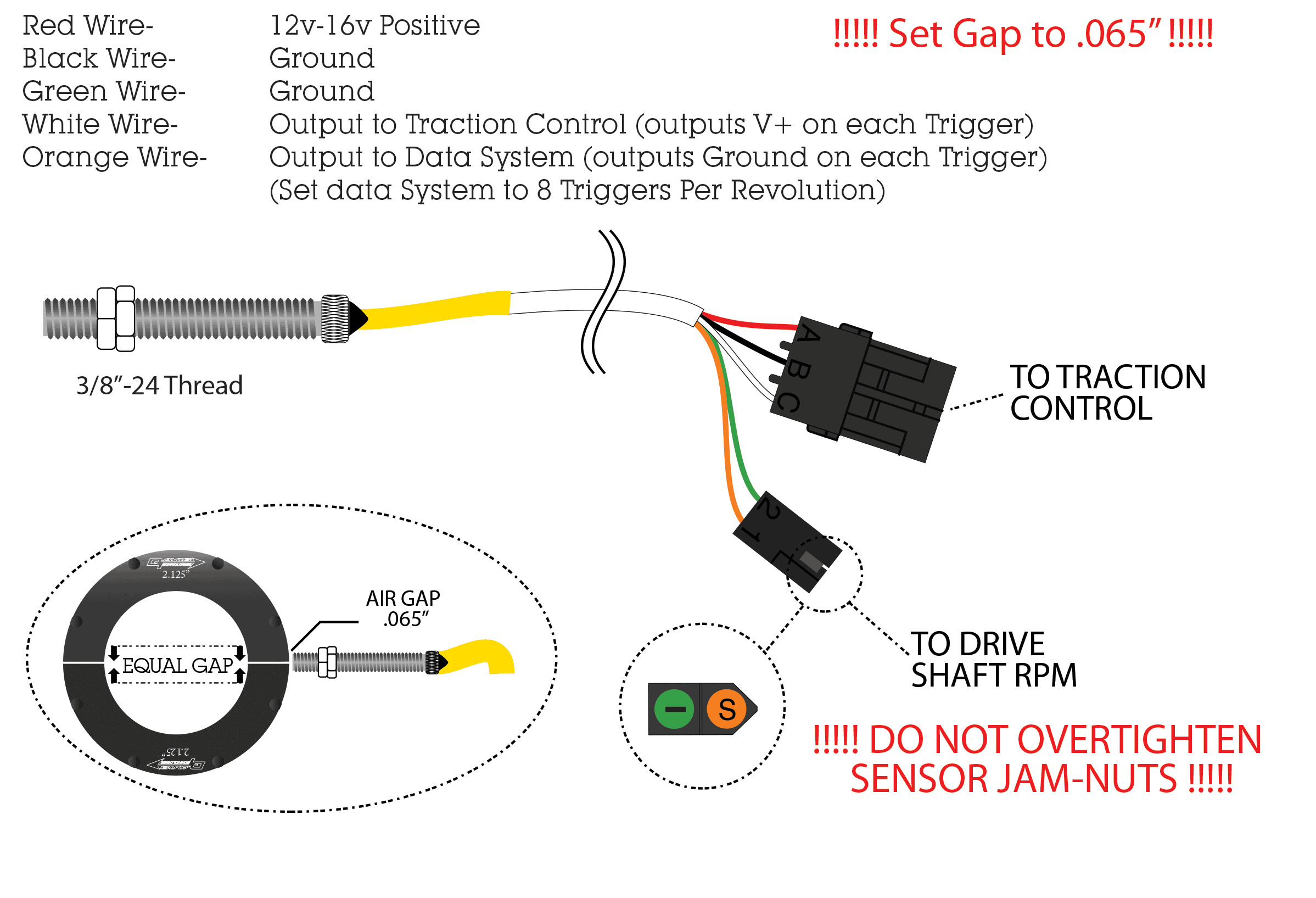 Source: moretraction.com
You will need to connect the 4 wires from the racepak iq3 dash to the provided 8 pin can connector. You will need to connect the 4 wires from the racepak iq3 dash to the provided 8 pin can connector. Iq3 / motec interface module wiring diagram for m8 ecu. All other wires are provided with t he pins crimped and ready to. Button wiring diagram chassis ground or.
This site is an open community for users to share their favorite wallpapers on the internet, all images or pictures in this website are for personal wallpaper use only, it is stricly prohibited to use this wallpaper for commercial purposes, if you are the author and find this image is shared without your permission, please kindly raise a DMCA report to Us.
If you find this site convienient, please support us by sharing this posts to your own social media accounts like Facebook, Instagram and so on or you can also bookmark this blog page with the title racepak dash wiring diagram by using Ctrl + D for devices a laptop with a Windows operating system or Command + D for laptops with an Apple operating system. If you use a smartphone, you can also use the drawer menu of the browser you are using. Whether it’s a Windows, Mac, iOS or Android operating system, you will still be able to bookmark this website.
Category
Related By Category
- Predator 670 engine wiring diagram Idea
- Frsky x8r wiring diagram information
- Pioneer ts wx130da wiring diagram Idea
- Johnson 50 hp wiring diagram Idea
- Kohler voltage regulator wiring diagram Idea
- Johnson 50 hp outboard wiring diagram information
- Kti hydraulic remote wiring diagram Idea
- Pyle plpw12d wiring diagram information
- Tx9600ts wiring diagram information
- Lifan 50cc wiring diagram information