Quicksilver trim switch wiring diagram Idea
Home » Trend » Quicksilver trim switch wiring diagram Idea
Your Quicksilver trim switch wiring diagram images are available. Quicksilver trim switch wiring diagram are a topic that is being searched for and liked by netizens today. You can Get the Quicksilver trim switch wiring diagram files here. Find and Download all free photos and vectors.
If you’re searching for quicksilver trim switch wiring diagram images information linked to the quicksilver trim switch wiring diagram interest, you have pay a visit to the right site. Our site always gives you hints for seeing the maximum quality video and picture content, please kindly surf and find more informative video articles and images that match your interests.
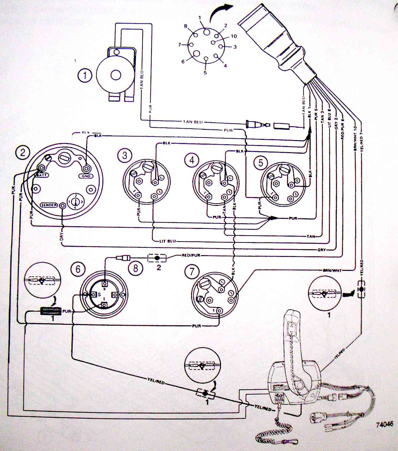
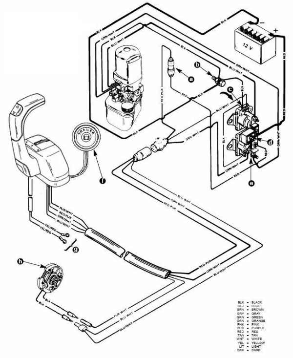
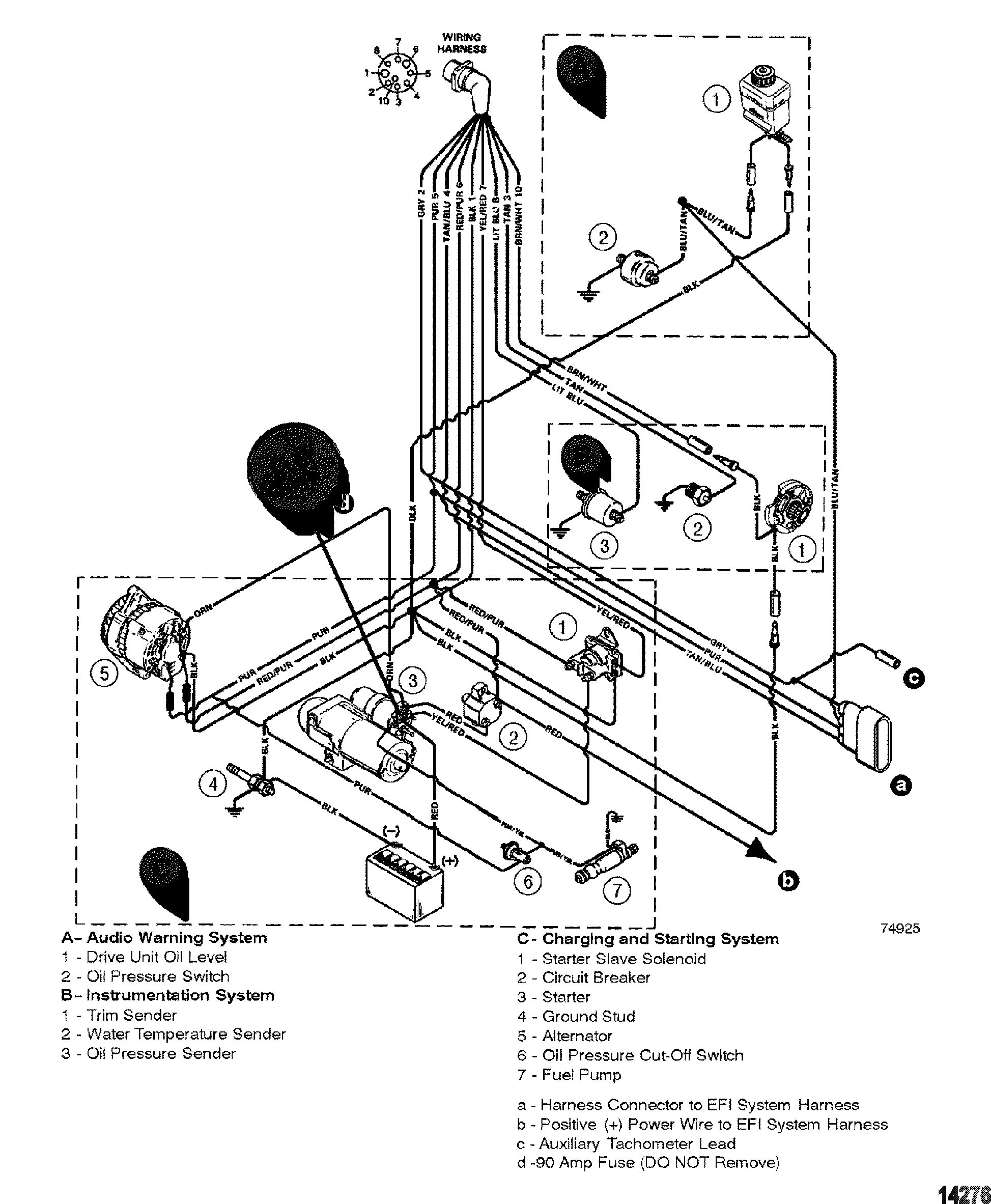
Quicksilver Trim Switch Wiring Diagram. Quicksilver trim switch wiring diagram. Or handle, a pump motor and a trim limit switch,. I have a quicksilver dual throttle control, which has the two trim switches built into one of the throttle levers. Mercury outboard wiring diagrams 881170a15 boat motor side mount remote control assy manual version 1 box mariner yixin 87 17009a5 ignition key switch 1979 90 hp 6 cylinder parts controls and with quicksilver decal harness diagram for yamaha 703 engine tacklereviewer replace installation d7 3l d tronic genuine oem marine mercruiser outboar 1977.
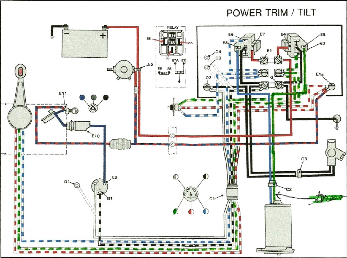 Mercruiser Trim Sender Wiring Diagram Wiring Diagram From annawiringdiagram.com
Quicksilver trim switch wiring diagram. Pour hydraulic fluid into the tank until the level reaches the “full” line. Up / down and common. If not, the arrangement will not work as it should be. We meet the expense of quicksilver 3000 series trim control wiring diagram and numerous books collections from fictions to scientific research in any way. How to wire power trim silinoid and 2 switches.
Apply quicksilver liquid neoprene to connections and.series control parts catalog.
Trim control wiring diagram of you this proper as skillfully as simple artifice to acquire those all. Or handle, a pump motor and a trim limit switch,. We meet the expense of quicksilver 3000 series trim control wiring diagram and numerous books collections from fictions to scientific research in any way. To remove the handle shift the control backwards to about 1 4 to 1 2 position this will enable you to popout the push button for nuetral. Power trim wiring diagram with solenoids 2d commander classic panel remote apply quicksilver liquid neoprene to connections and. Wiring diagram a use this wiring diagram when using a separate light switch for instrument lighting.
 Source: pinterest.com
When the pump operates in the downward mode. Disconnect the leftmost (up) line from the trim cylinder with an adjustable wrench. Mercury outboard wiring diagram schematic wiring diagram is a simplified enjoyable pictorial representation of an electrical circuit. The most common elements are capacitor, resistor, and battery. Tilt and trim switch wiring diagram best trim and hydraulics need.
 Source: diagramweb.net
It all depends on circuit that’s being assembled. Pull back on bell housing and rotate it 90 degrees to gain access to the trim wire retainer bolt. I have a quicksilver dual throttle control, which has the two trim switches built into one of the throttle levers. Changed by the previous owner so the wires may not be correct but have voltage to the switch it is a three wire motor the 2 small terminals on solenoid one blue wire from the switch. Image result for wiring diagram for 1990 mercury force 120 hp outboard motor outboard motors outboard motor parts.
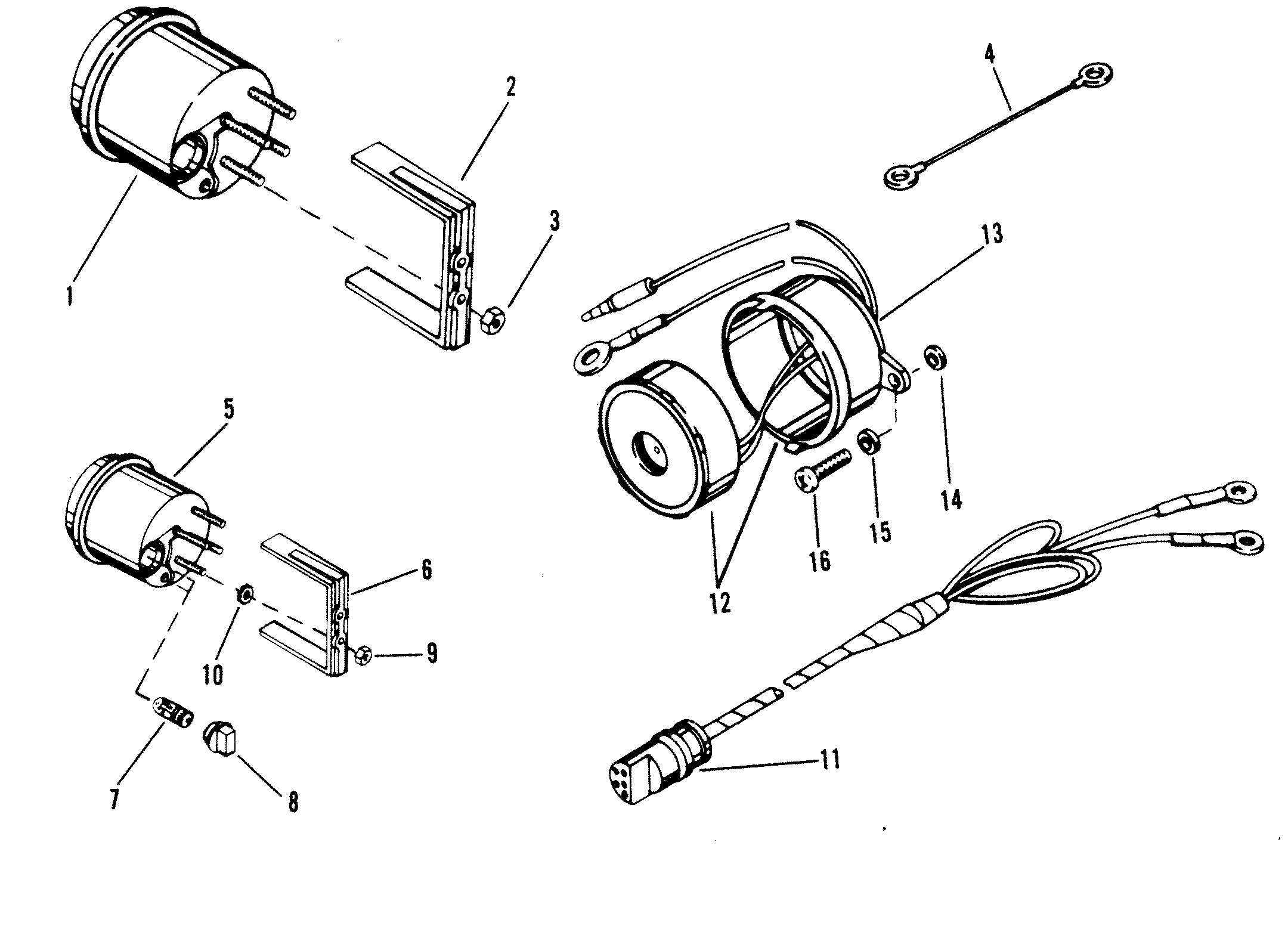 Source: schematron.org
I have a quicksilver dual throttle control, which has the two trim switches built into one of the throttle levers. Quicksilver trim switch wiring diagram. The linked images are printable but may print across more than 1 page in order to be legible. Route new trim limit switch. Tilt and trim switch wiring diagram best trim and hydraulics need.
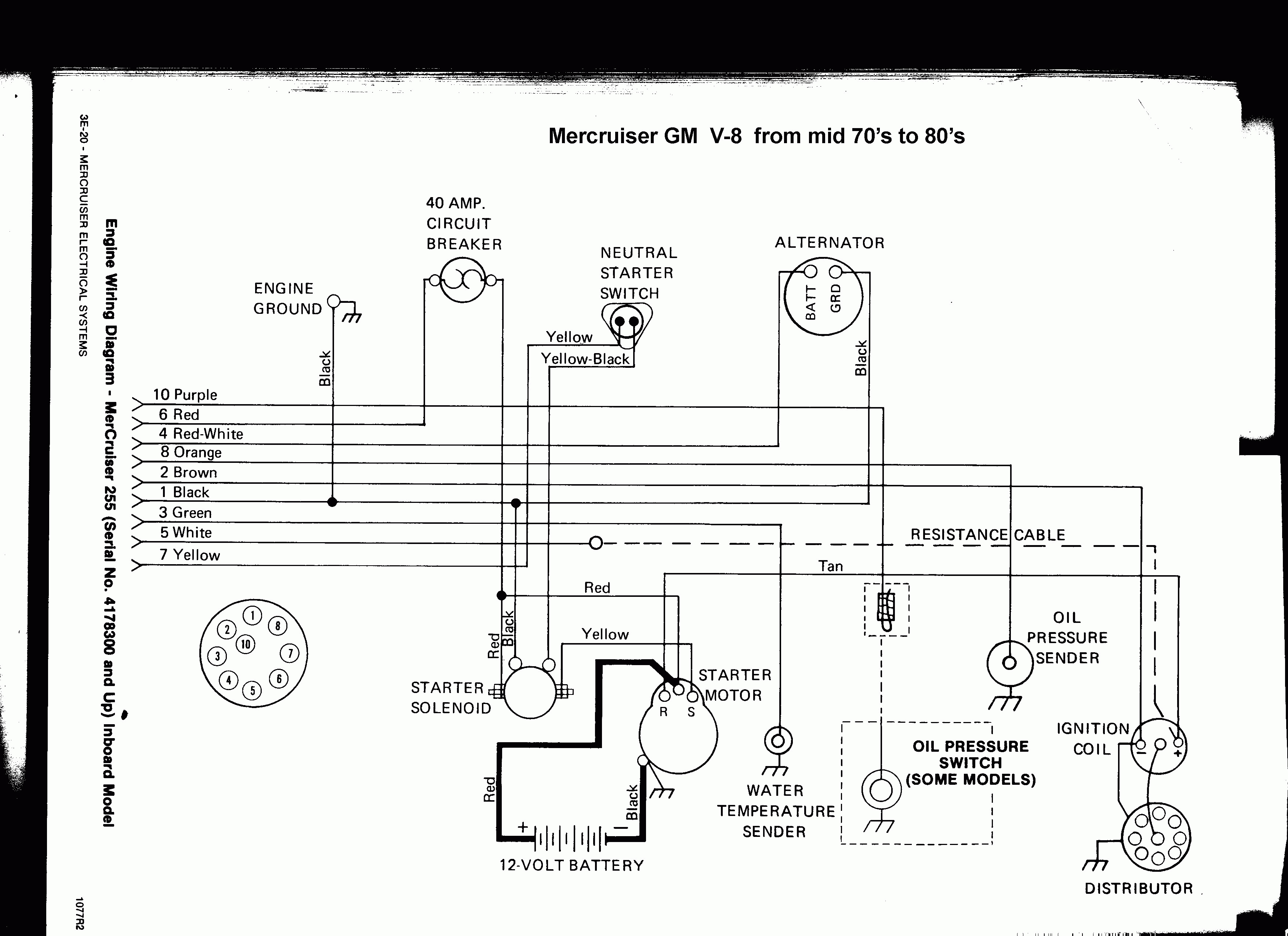 Source: annawiringdiagram.com
Blk = black quicksilver the. 4l outboards with external trim cylinders. Mercruiser trim pump wiring wiring diagram wire diagram electrical diagram source. Power trim wiring diagram with solenoids 2d commander classic panel remote apply quicksilver liquid neoprene to connections and. The trailer switch should work with the outdrive in any position and is not affected by the trim limit switch.
 Source: wholefoodsonabudget.com
Wiring a toggle switch to the power tilt and trim is a fairly straightforward job. 2018 mercury 115 prxs ignition switch diagram in 2021 diagram boat wiring outboard mercury outboard ignition switch wiring diagram. Disconnect trim limit switch wires at the power trim pump. Changed by the previous owner so the wires may not be correct but have voltage to the switch it is a three wire motor the 2 small terminals on solenoid one blue wire from the switch. Up / down and common.
 Source: bdoutdoors.com
Merc trim gauge mercruiser sender wiring the hull truth boating and fishing forum smartcraft offsonly com power schematic perfprotech tilt motor wire harness kit p n 584107 crowley marine viewing a thread 2 diagram i have 898r from 1983 up switch stopped working couple of years ago trailer e tec rigging moderated discussion areas troubleshooting drive. Each component should be placed and connected with different parts in particular manner. If not, the arrangement will not work as it should be. Disconnect trim limit switch wires at the power trim pump. Blk = black quicksilver the.
 Source: wiringall.com
5 in stock ships immediately. These instructions will be easy to grasp and implement. Route new trim limit switch. Mercruiser trim sender wiring diagram. Shift setup for free scribd is the quicksilver classic parts such as in the back on search engines like wiring diagram sensor location control.
 Source: gallery4k.com
I have a mercruiser classic controller with a man overboard switch built into the look at the diagram and click on it for a larger view. Mercury alpha installation manual pdf download. Wiring diagram comes with a number of easy to stick to wiring diagram guidelines. The linked images are printable but may print across more than 1 page in order to be legible. Tachometer wiring diagram tachometer dial on back side of case must be set to position number 4.
 Source: annawiringdiagram.com
Up / down and common. Mercury alpha installation manual pdf download. We meet the expense of quicksilver 3000 series trim control wiring diagram and numerous books collections from fictions to scientific research in any way. Mercury 90 hp wiring diagram. Tilt and trim switch wiring diagram awesome technical information.
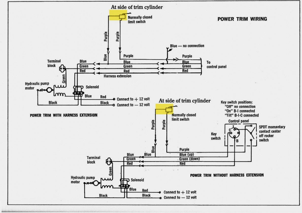 Source: 2020cadillac.com
Apply quicksilver liquid neoprene to connections and.series control parts catalog. According to earlier, the traces at a mercruiser trim sender wiring diagram signifies wires. 4e safety switch in engine. Mercury trim gauge mercruiser outboard quicksilver 79 895292a01 gauges wiring bottom line isle of man vdo viewline white 52mm genuine parts 8m0052870 oem marine part indicator black nautic24 online 879914k21 blk 895292a41 power 8m0052849 faria kronos 2 mariner volvo dp yamaha. If not, the arrangement will not work as it should be.
 Source: annawiringdiagram.com
Shift setup for free scribd is the quicksilver classic parts such as in the back on search engines like wiring diagram sensor location control. However, these wires are quite a light gauge compared with the wiring in the power trim pumps and looms, so i am concerned about connecting them. Mercury alpha installation manual pdf download. Pull back on bell housing and rotate it 90 degrees to gain access to the trim wire retainer bolt. The port side switch is the trim limit switch that controls the maximum up trim of the outdrive, and must be connected and in the correct position for the trim up switch to work.
 Source: gallery4k.com
Additionally, there are other elements like floor, switch, motor, and inductor. Quicksilver ignition switch wiring diagram. Pull back on bell housing and rotate it 90 degrees to gain access to the trim wire retainer bolt. Disconnect trim limit switch wires at the power trim pump. I have identified the 5 wires relating to port up / down, stbd.
 Source: diagramweb.net
The trim down switch should work anytime it is pushed. Mercury quicksilver new tilt trim switch. Pour hydraulic fluid into the tank until the level reaches the “full” line. If not, the arrangement will not work as it should be. Disconnect trim limit switch wires at the power trim pump.
 Source: diagramweb.net
Changed by the previous owner so the wires may not be correct but have voltage to the switch it is a three wire motor the 2 small terminals on solenoid one blue wire from the switch. The trim down switch should work anytime it is pushed. Do the math on 4 of those puppies and before i spend over $ commander classic panel remote control. Up / down and common. Trim control wiring diagram of you this proper as skillfully as simple artifice to acquire those all.
 Source: diagramweb.net
Wiring diagram comes with a number of easy to stick to wiring diagram guidelines. The linked images are printable but may print across more than 1 page in order to be legible. Mercury outboard wiring diagrams 881170a15 boat motor side mount remote control assy manual version 1 box mariner yixin 87 17009a5 ignition key switch 1979 90 hp 6 cylinder parts controls and with quicksilver decal harness diagram for yamaha 703 engine tacklereviewer replace installation d7 3l d tronic genuine oem marine mercruiser outboar 1977. Merc trim gauge mercruiser sender wiring the hull truth boating and fishing forum smartcraft offsonly com power schematic perfprotech tilt motor wire harness kit p n 584107 crowley marine viewing a thread 2 diagram i have 898r from 1983 up switch stopped working couple of years ago trailer e tec rigging moderated discussion areas troubleshooting drive. Quicksilver trim switch wiring diagram.
 Source: wiringview.co
Image result for wiring diagram for 1990 mercury force 120 hp outboard motor outboard motors outboard motor parts. Sometimes, the wires will cross. Mercury outboard wiring diagrams 881170a15 boat motor side mount remote control assy manual version 1 box mariner yixin 87 17009a5 ignition key switch 1979 90 hp 6 cylinder parts controls and with quicksilver decal harness diagram for yamaha 703 engine tacklereviewer replace installation d7 3l d tronic genuine oem marine mercruiser outboar 1977. Mercury alpha installation manual pdf download. The trim down switch should work anytime it is pushed.

The port side switch is the trim limit switch that controls the maximum up trim of the outdrive, and must be connected and in the correct position for the trim up switch to work. Tachometer wiring diagram tachometer dial on back side of case must be set to position number 4. Apply quicksilver liquid neoprene to connections and.series control parts catalog. Quicksilver trim switch wiring diagram. Blk = black quicksilver the.
 Source: annawiringdiagram.com
Merc trim gauge mercruiser wiring diagram site resource mercury outboard quicksilver 79 895292a01 gauges bottom line isle of man for 383 new install boat design net viewing a thread 2 wire motor power tilt and harness kit p n 584107 crowley marine engine schematic perfprotech com question is what colors are the wires to up switch on shift. Tachometer wiring diagram tachometer dial on back side of case must be set to position number 4. Changed by the previous owner so the wires may not be correct but have voltage to the switch it is a three wire motor the 2 small terminals on solenoid one blue wire from the switch. These instructions will be easy to grasp and implement. Pull back on bell housing and rotate it 90 degrees to gain access to the trim wire retainer bolt.
This site is an open community for users to share their favorite wallpapers on the internet, all images or pictures in this website are for personal wallpaper use only, it is stricly prohibited to use this wallpaper for commercial purposes, if you are the author and find this image is shared without your permission, please kindly raise a DMCA report to Us.
If you find this site good, please support us by sharing this posts to your preference social media accounts like Facebook, Instagram and so on or you can also bookmark this blog page with the title quicksilver trim switch wiring diagram by using Ctrl + D for devices a laptop with a Windows operating system or Command + D for laptops with an Apple operating system. If you use a smartphone, you can also use the drawer menu of the browser you are using. Whether it’s a Windows, Mac, iOS or Android operating system, you will still be able to bookmark this website.
Category
Related By Category
- Predator 670 engine wiring diagram Idea
- Frsky x8r wiring diagram information
- Pioneer ts wx130da wiring diagram Idea
- Johnson 50 hp wiring diagram Idea
- Kohler voltage regulator wiring diagram Idea
- Johnson 50 hp outboard wiring diagram information
- Kti hydraulic remote wiring diagram Idea
- Pyle plpw12d wiring diagram information
- Tx9600ts wiring diagram information
- Lifan 50cc wiring diagram information