Qd control box wiring diagram Idea
Home » Trend » Qd control box wiring diagram Idea
Your Qd control box wiring diagram images are available. Qd control box wiring diagram are a topic that is being searched for and liked by netizens today. You can Download the Qd control box wiring diagram files here. Get all royalty-free photos and vectors.
If you’re searching for qd control box wiring diagram images information linked to the qd control box wiring diagram keyword, you have come to the right site. Our website always provides you with suggestions for seeing the highest quality video and picture content, please kindly search and find more enlightening video articles and graphics that fit your interests.
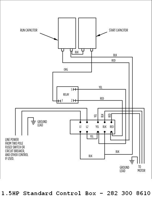
Qd Control Box Wiring Diagram. If not, the arrangement won’t function. Using this guidebook, you’ll be in a position to find out how each part should be connected as well as the actual steps you ought to take to be able to effectively total a specific job. Franklin electric qd control box wiring diagram wiring diagram line wiring diagram wiring diagram line we are make source the. Assortment of submersible pump wiring diagram.
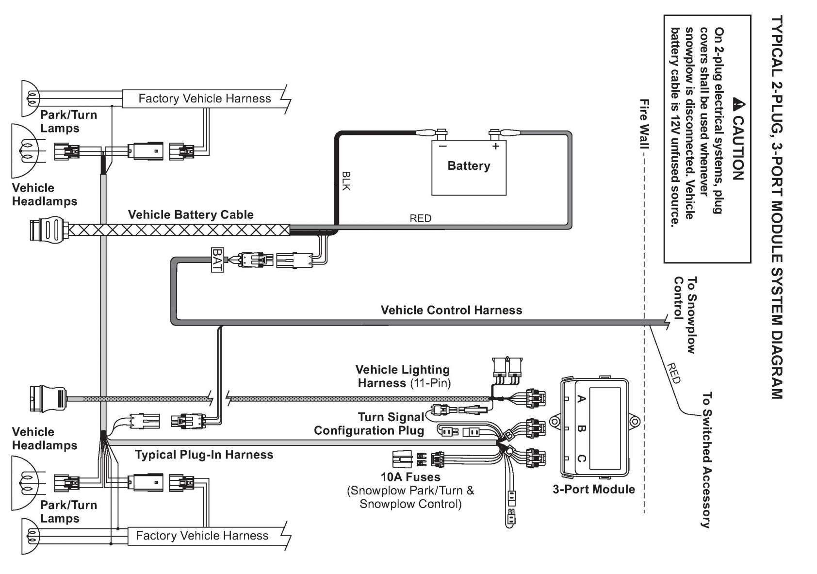
 Franklin Qd Control Relay Wiring Diagram From schematron.org
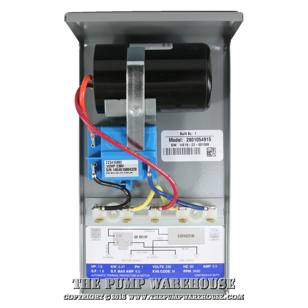
Submersible pump control box wiring diagram. • press the pumpsaver onto the l1 and l2 terminals. Franklin electric submersible motor control wiring diagram franklin qd control box 1 2 hp 115v To install in cp, qd control box: If not, the arrangement won’t function. Franklin electric submersible pump wiring diagram.
Quick disconnect (qd) boxes make trouble shooting simple by automatically disconnecting the control components from the system when the lid is removed.
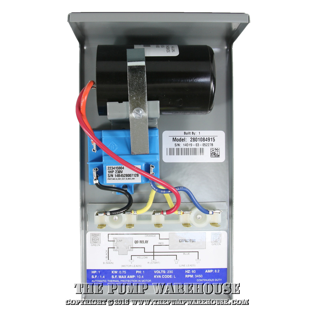
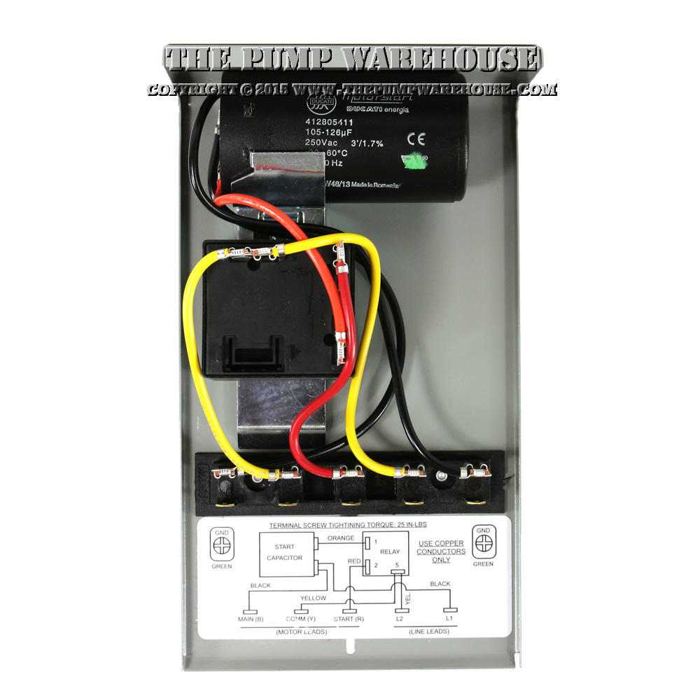
Using this guidebook, you’ll be in a position to find out how each part should be connected as well as the actual steps you ought to take to be able to effectively total a specific job. On franklin qd control relay wiring diagram. To install in cp, qd control box: Franklin 1hp 230v qd control box (required for 3 wire motors) type: 3 wires plus 1 ground wire. Reconnect the red wire to its original position (start terminal) on the control box terminal strip.
 Source: youtube.com
Red, yellow, black from the pump (no ground). A wiring diagram is a streamlined standard pictorial depiction of an electric circuit. Franklin qd control box 1 hp 230v electric 2801044915 submersible motor 0 5 115v 1ph for 3 wire motors fec2801044915 latin america cajas de standard 2 pump panel ac compatible type deep well no switch included 1lzv7 558831 grainger single phase pumps bo flowise with quick disconnect and easy connect design deluxe water 2801054915 new. • press the pumpsaver onto the l1 and l2 terminals. Franklin electric submersible motor control wiring diagram franklin qd control box 1 2 hp 115v
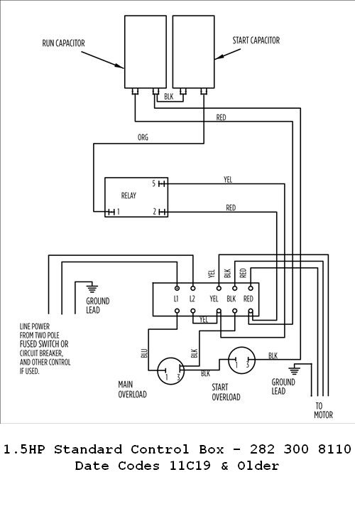 Source: wiringdiagram.2bitboer.com
Aim manual page 53 single phase motors and controls motor maintenance north america water franklin electric 54 1hp 230v qd control box 55 56 2801044915 submersible 0 5 hp 115v 1ph for 3 wire fec2801044915 deluxe 2 well pumps bo 57 pump panel ac compatible type deep no switch included 1lzx2 558811 grainger 1 2hp crc flowise with quick disconnect easy. Franklin qd control box 1 hp 230v electric 2801044915 submersible motor 0 5 115v 1ph for 3 wire motors fec2801044915 latin america cajas de standard 2 pump panel ac compatible type deep well no switch included 1lzv7 558831 grainger single phase pumps bo flowise with quick disconnect and easy connect design deluxe water 2801054915 new. Each part should be placed and linked to other parts in particular way. Franklin electric qd control box wiring diagram. Control box, qd (quick disconnect) hp:
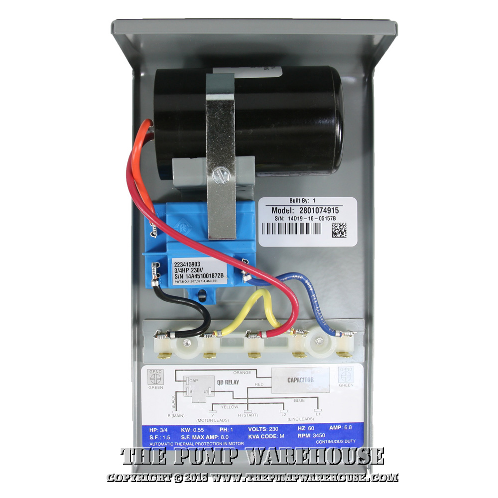 Source: thepumpwarehouse.com
Read and follow safety instructions this is the safety alert symbol. Read and follow safety instructions this is the safety alert symbol. As below, the standard board operates from 24v and must use 12v horns and lighting. Connect emergency stop and 3 button pendant run the bundle of cables from the gantry to the control box and through the cable entry on the end of the control box. A wiring diagram is a streamlined standard pictorial depiction of an electric circuit.
 Source: solarpowerandpump.com
Aim manual page 54 single phase motors and controls motor maintenance north america water franklin electric. As below, the standard board operates from 24v and must use 12v horns and lighting. Type 3r enclosure suitable for outdoor mounting, not gasketed, two holes for wall mounting at back of box. Red, yellow, black from the pump (no ground). Aim manual page 53 single phase motors and controls motor maintenance north america water franklin electric 54 1hp 230v qd control box 55 56 2801044915 submersible 0 5 hp 115v 1ph for 3 wire fec2801044915 deluxe 2 well pumps bo 57 pump panel ac compatible type deep no switch included 1lzx2 558811 grainger 1 2hp crc flowise with quick disconnect easy.
 Source: diagramweb.net
Franklin 1hp 230v qd control box (required for 3 wire motors) type: 1 3 1 hp qd relay 280 10 4915 sixth digit depends on hp. This can be helpful for the two the folks and for experts who’re seeking for more information on how to established up a working environment. A wiring diagram is a streamlined standard pictorial depiction of an electric circuit. Franklin electric control boxes are in stock and ship free.
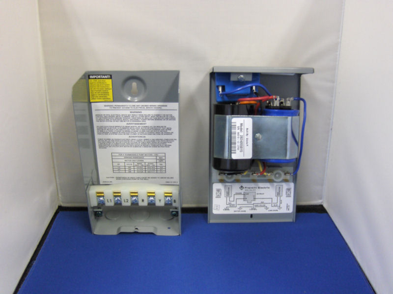 Source: wiringdiagram.2bitboer.com
Franklin electric control boxes are in stock and ship free. Using this guidebook, you’ll be in a position to find out how each part should be connected as well as the actual steps you ought to take to be able to effectively total a specific job. A wiring diagram is a simplified conventional pictorial representation of an electric circuit. • remove the yellow wire from the terminal strip at l2. Franklin qd control box 1 hp 230 volts phase 2801084915.
 Source: schematron.org
Quick disconnect (qd) boxes make trouble shooting simple by automatically disconnecting the control components from the system when the lid is removed. Check voltage output on the red and black wire. A wiring diagram is a streamlined standard pictorial depiction of an electric circuit. Franklin electric qd control box wiring diagram. Franklin deluxe control box 2 hp 230v.
 Source: detoxicrecenze.com
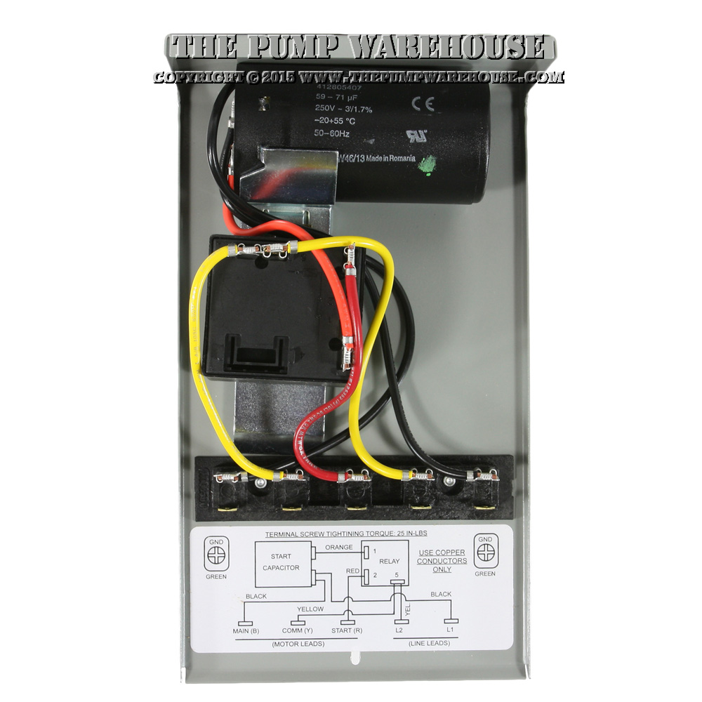
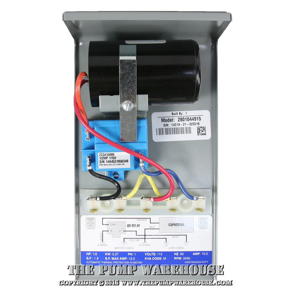
Franklin qd control box 1/2 hp 115 volts 1 phase # 2801044915. Assortment of submersible pump wiring diagram. Franklin qd control box parts breakdown. Submersible pump control box wiring diagram. Wiring diagram for control box well pump evinrude etec schematics code 03 honda accordd waystar fr.
 Source: thepumpwarehouse.com
If not the structure will not work as it should be. Each part should be placed and linked to other parts in particular way. Type 3r enclosure suitable for outdoor mounting, not gasketed, two holes for wall mounting at back of box. Has knockouts in the bottom and sides. Red, yellow, black from the pump (no ground).
 Source: detoxicrecenze.com
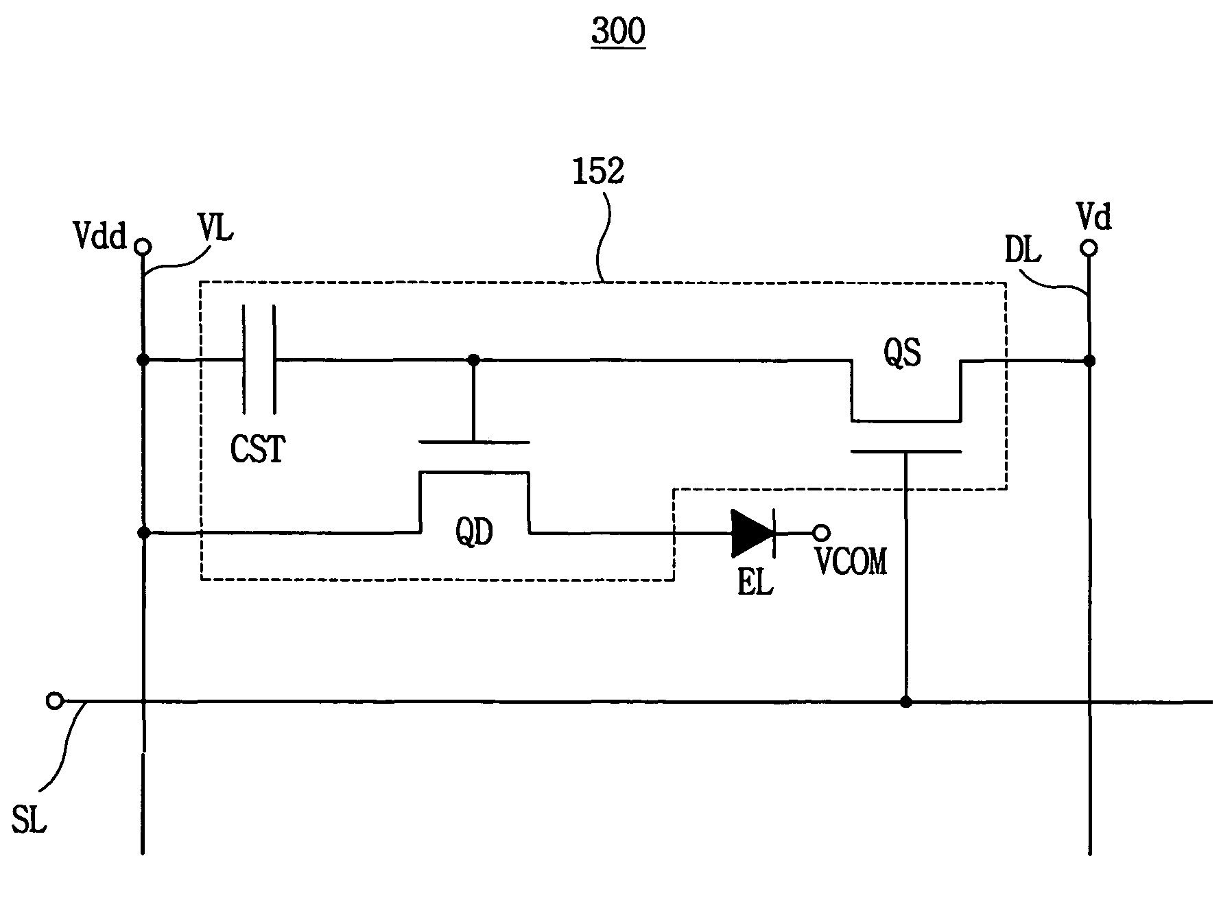
Franklin qd control box parts breakdown. Submersible pump control box wiring diagram. 1/3 to 1hp qd control box wiring diagram. A wiring diagram is a streamlined standard pictorial depiction of an electric circuit. Effectively read a wiring diagram one offers to learn how typically the components inside the method operate.
 Source: thepumpwarehouse.com
Connect emergency stop and 3 button pendant run the bundle of cables from the gantry to the control box and through the cable entry on the end of the control box. In the case of franklin electric control boxes, there�s much more to the a surge arrestor, protecting the qd relay and the motor from electrical. Control box, qd (quick disconnect) hp: 1/3 to 1hp qd control box wiring diagram. If not the structure will not work as it should be.
 Source: thepumpwarehouse.com
Franklin qd control box parts breakdown. A wiring diagram is a simplified conventional pictorial representation of an electric circuit. Franklin electric qd control box wiring diagram wiring diagram line wiring diagram wiring diagram line we are make source the. A wiring diagram is a streamlined standard pictorial depiction of an electric circuit. • press the pumpsaver onto the l1 and l2 terminals.
 Source: pinterest.com
Single phase motors and controls franklin electric 2822029330 deluxe qd control box 1 2 hp 115v 230v 5 submersible motor 2801044915 panel of water pump super stainless 0 230 volts wiring troubleshooting 3. On franklin qd control relay wiring diagram. • press the pumpsaver onto the l1 and l2 terminals. Franklin electric submersible pump wiring diagram. Set up (see attached diagram):
 Source: wiringdiagram.2bitboer.com
Franklin qd control box 1 hp 230v electric 2801044915 submersible motor 0 5 115v 1ph for 3 wire motors fec2801044915 latin america cajas de standard 2 pump panel ac compatible type deep well no switch included 1lzv7 558831 grainger single phase pumps bo flowise with quick disconnect and easy connect design deluxe water 2801054915 new. Franklin electric 2801044915 qd submersible motor control box 0 5 hp 115v 1ph for 3 wire motors fec2801044915. Connect the yellow wire to the terminal marked l2 on the qd pumptec. • reconnect the yellow wire to l2 on the pumpsaver. Control box, qd (quick disconnect) hp:
 Source: thepumpwarehouse.com
Connect emergency stop and 3 button pendant run the bundle of cables from the gantry to the control box and through the cable entry on the end of the control box. Reconnect the red wire to its original position (start terminal) on the control box terminal strip. Each part should be placed and linked to other parts in particular way. 3 wires plus 1 ground wire. A wiring diagram is a streamlined standard pictorial depiction of an electric circuit.
 Source: thepumpwarehouse.com
Has knockouts in the bottom and sides. To install in cp, qd control box: Franklin 1hp 230v qd control box (required for 3 wire motors) type: In this video, chris shows you how to wire the franklin electric qd control box. Set up (see attached diagram):
 Source: cikcapuccinolatte.blogspot.com
Has knockouts in the bottom and sides. Single phase motors and controls franklin electric 2822029330 deluxe qd control box 1 2 hp 115v 230v 5 submersible motor 2801044915 panel of water pump super stainless 0 230 volts wiring troubleshooting 3. Connect emergency stop and 3 button pendant run the bundle of cables from the gantry to the control box and through the cable entry on the end of the control box. If not, the arrangement won’t function. Franklin qd control box 1 hp 230v electric 2801044915 submersible motor 0 5 115v 1ph for 3 wire motors fec2801044915 latin america cajas de standard 2 pump panel ac compatible type deep well no switch included 1lzv7 558831 grainger single phase pumps bo flowise with quick disconnect and easy connect design deluxe water 2801054915 new.
 Source: detoxicrecenze.com
Each part should be placed and linked to other parts in particular way. Aim manual page 54 single phase motors and controls motor maintenance north america water franklin electric. 3 wire submersible pump wiring diagram. Otherwise, the structure won’t work as it should be. Franklin electric control boxes are in stock and ship free.
This site is an open community for users to do submittion their favorite wallpapers on the internet, all images or pictures in this website are for personal wallpaper use only, it is stricly prohibited to use this wallpaper for commercial purposes, if you are the author and find this image is shared without your permission, please kindly raise a DMCA report to Us.
If you find this site adventageous, please support us by sharing this posts to your favorite social media accounts like Facebook, Instagram and so on or you can also save this blog page with the title qd control box wiring diagram by using Ctrl + D for devices a laptop with a Windows operating system or Command + D for laptops with an Apple operating system. If you use a smartphone, you can also use the drawer menu of the browser you are using. Whether it’s a Windows, Mac, iOS or Android operating system, you will still be able to bookmark this website.
Category
Related By Category
- Predator 670 engine wiring diagram Idea
- Frsky x8r wiring diagram information
- Pioneer ts wx130da wiring diagram Idea
- Johnson 50 hp wiring diagram Idea
- Kohler voltage regulator wiring diagram Idea
- Johnson 50 hp outboard wiring diagram information
- Kti hydraulic remote wiring diagram Idea
- Pyle plpw12d wiring diagram information
- Tx9600ts wiring diagram information
- Lifan 50cc wiring diagram information