Pump control wiring diagram Idea
Home » Trend » Pump control wiring diagram Idea
Your Pump control wiring diagram images are ready in this website. Pump control wiring diagram are a topic that is being searched for and liked by netizens today. You can Get the Pump control wiring diagram files here. Get all free photos.
If you’re searching for pump control wiring diagram images information connected with to the pump control wiring diagram topic, you have pay a visit to the ideal blog. Our site always provides you with hints for viewing the highest quality video and image content, please kindly surf and find more enlightening video articles and images that fit your interests.
Pump Control Wiring Diagram. When the switch detects liquid the contacts will close and the pump motor. As shown in the diagram you will need to power up the thermostat and the 24v ac power is connected to the r and c terminals. Two wires, and you’re done. It shows the elements of the circuit as streamlined forms, and the power and signal connections in between the devices.
 Find Out Here Duplex Pump Control Panel Wiring Diagram From worldvisionsummerfest.com
Three phase submersible pump control microcontroller wiring 3 panel simplex diagram starter single motors and controls metal wapro open well mini openwell mcb pgm 6 dol controller solar inverter circuit electric board water troubleshooting ws1p tp 40kw motor म टर क ट र लर for molock goulds. 220v 3 wire well pump wiring diagram. 220v 3 wire well pump wiring diagram. As shown in the diagram you will need to power up the thermostat and the 24v ac power is connected to the r and c terminals. Always follow the manufacturer’s instructions for both the thermostat and the hvac system. Fire pump controller wiring diagram be126 fire fighting controller home page !!
It shows the elements of the circuit as streamlined forms, and the power and signal connections in between the devices.
Submersible pump control box wiring diagram for 3 wire single phase. Wiring diagram for 220 volt submersible pump bookingritzcarlton info in 2021 submersible well pump submersible pump submersible. When the switch detects liquid the contacts will close and the pump motor. Red and yellow might indicate that it is a 2 wire 220 volt pump. 240 volt well pump wiring diagram wiring diagram is a simplified all right pictorial representation of an electrical circuit it shows the components of the circuit as simplified shapes and the faculty and signal contacts amongst the devices. 3 wire well pump wiring diagram wiring diagram is a simplified.
 Source: worldvisionsummerfest.com
3 wire well pump wiring diagram wiring diagram is a simplified. This article describes troubleshooting a submersible well pump that was causing tripped circuit breakers and that pumped water only at a slow, reduced rate and pressure. A wiring diagram is an easy visual representation in the physical connections and physical layout of an electrical system or circuit. Fire pump controller wiring diagram be126 fire fighting controller home page !! Gb subdrive75/00/50 constant pressure controller installation manual contents controller model franklin electric motor model rated power kw hp,5.
 Source: ricardolevinsmorales.com
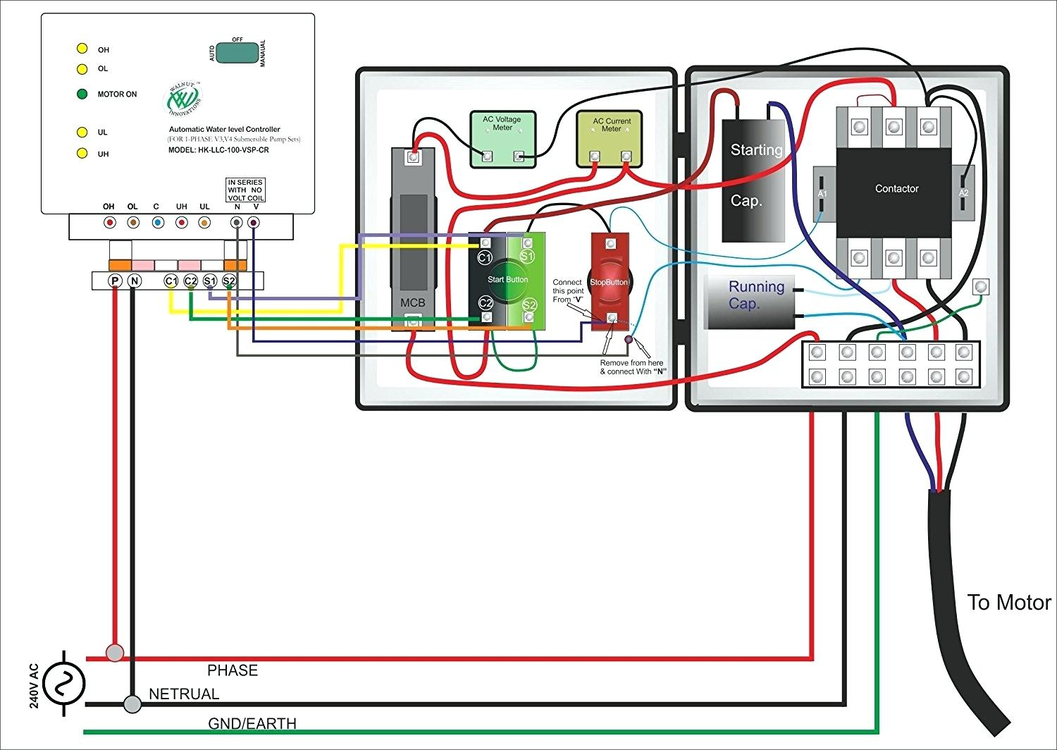
56 20 fuel pump relay fuel pump control module fpcm. Make sure the pump electrical supply circuit is equipped with fuses or circuit breakers of proper capacity. Pump control panel wiring diagram schematic. The wiring connection of submersible pump control box is very simple. Home decorating style 2022 for grundfos pump control panel wiring diagram, you can see grundfos pump control panel wiring diagram and more pictures for home interior designing 2022 318959 at resume example ideas.
 Source: researchgate.net
Submersible pump control box wiring diagram for 3 wire single phase submersible pump submersible well pump submersible wiring diagram for 220 volt submersible pump submersible pump 1993 ford mustang wiring diagram 2001 ford mus submersible pump submersible well pump sump pump Home decorating style 2022 for grundfos pump control panel wiring diagram, you can see grundfos pump control panel wiring diagram and more pictures for home interior designing 2022 318959 at resume example ideas. Control panel for 1 h p submersible pumps with timer ltems t 1050 ewatercart com. Control box wiring diagrams (continued). It shows the elements of the circuit as streamlined forms, and the power and signal connections in between the devices.
 Source: cikcapuccinolatte.blogspot.com
Submersible pump control box wiring diagram for 3 wire single phase. Red and yellow might indicate that it is a 2 wire 220 volt pump. 2 wire well pump diagrams are slightly easier to understand and are more straight forward to wire. 2 built in bilge running indicator. All electrical and safety codes should be followed including the most recent national electric code (nec) and the occupational safety and health act (osha).phone.
 Source: annawiringdiagram.com
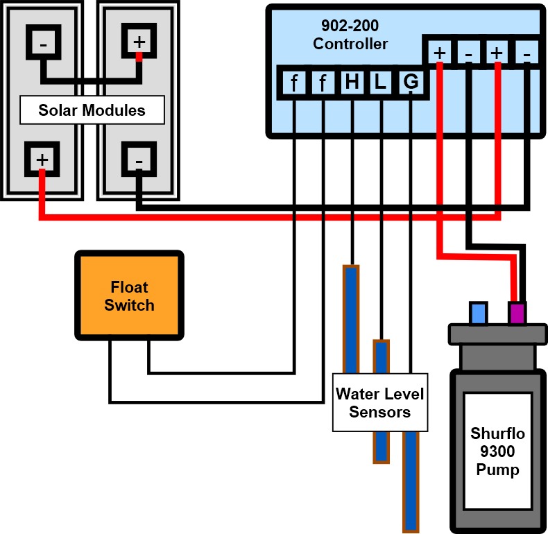
A wiring diagram is an easy visual representation in the physical connections and physical layout of an electrical system or circuit. A float switch consists of the floating switch and the electrical wire. This article describes troubleshooting a submersible well pump that was causing tripped circuit breakers and that pumped water only at a slow, reduced rate and pressure. Control panel for 1 h p submersible pumps with timer ltems t 1050 ewatercart com. Three phase submersible pump starter bch electric limited.
 Source: worldvisionsummerfest.com
Control box wiring diagrams (continued). 3 wire well pump wiring diagram wiring diagram is a simplified. 220v 3 wire well pump wiring diagram. Dedicated circuit for well pumps. A separate branch circuit is recommended, sized.
 Source: worldvisionsummerfest.com
Submersible pump control box wiring diagram for 3 wire single phase submersible pump submersible well pump electrical circuit diagram Assortment of submersible pump control box wiring diagram. Always follow the manufacturer’s instructions for both the thermostat and the hvac system. Duplex pump control panel wiring diagram inspirational dump trailer. Red and yellow might indicate that it is a 2 wire 220 volt pump.
 Source: headcontrolsystem.com
Three phase submersible pump starter bch electric limited. All electrical and safety codes should be followed including the most recent national electric code (nec) and the occupational safety and health act (osha).phone. Two wires, and you’re done. 220v 3 wire well pump wiring diagram. A wiring diagram is a streamlined tolerable pictorial representation of an electric circuit goulds submersible pump wiring diagram download assortment of submersible pump wiring diagram may 21 2019 single phase 3 wire submersible pump control box wiring diagram.
 Source: 2020cadillac.com
Find all fire pump controller drawings as well as jockey pump controller, remote alarm panel, and low suction shutdown controller drawings here. Duplex pump control panel wiring diagram inspirational dump trailer. 240 volt well pump wiring diagram wiring diagram is a simplified all right pictorial representation of an electrical circuit it shows the components of the circuit as simplified shapes and the faculty and signal contacts amongst the devices. Well pump wiring diagnosis & repair: Franklin electric pump controller model 2823 wiring diagram.
 Source: worldvisionsummerfest.com
All electrical and safety codes should be followed including the most recent national electric code (nec) and the occupational safety and health act (osha).phone. Well pump wiring diagnosis & repair: Balboa spa pump wiring diagrams. We can go back to control schematic 1: 3 wire well pump wiring diagram wiring diagram is a simplified.
 Source: ricardolevinsmorales.com
3 wire well pump wiring diagram wiring diagram is a simplified. 4oz bottle round metal 17oz bottle round plastic. So what do you need to wire this up? Bp 60hz spa control system wiring balboa liteld dakota skyker not heating no pump but selenoid click from pool valet installation manual circuit board quesion portable service help ref only water group 2406 application notes acura megatrol diagram online for spas hot tubs and. A separate branch circuit is recommended, sized.
Source: electricalonline4u.com
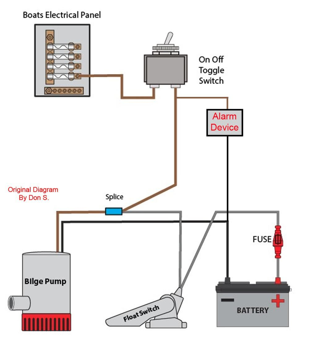
Duplex pump control panel wiring diagram inspirational dump trailer. The wiring connection of submersible pump control box is very simple. Home decorating style 2022 for grundfos pump control panel wiring diagram, you can see grundfos pump control panel wiring diagram and more pictures for home interior designing 2022 318959 at resume example ideas. Electrical diagrams motor phase pump with manual automatic float court esquemas electricos diagrama de instalacion electrica proyectos electricos. 3 backlit bilge rocker switch wiring diagram of the three bilge pump switches the only one thats not extremely simple is the backlit automanual bilge pump switch.
 Source: worldvisionsummerfest.com
The wiring connection of submersible pump control box is very simple. A wiring diagram is an easy visual representation in the physical connections and physical layout of an electrical system or circuit. It shows the elements of the circuit as streamlined forms, and the power and signal connections in between the devices. A wiring diagram is a type of schematic which uses abstract pictorial symbols to exhibit every one of the interconnections of components in the system. Well pump wiring diagnosis & repair:
 Source: humboldtsolarwaterpump.com
Ultimately using some simple electrical tests the homeowner traced the water pump problems to a nicked well pump wiring circuit wire. Franklin electric pump controller model 2823 wiring diagram. A separate branch circuit is recommended, sized. Perkins diesel injector pump diagram clear wiring diagram. All installation of controls, protection devices and wiring should be done by a qualified licensed electrician.
 Source: ricardolevinsmorales.com
Pump control panel wiring diagram schematic. Three phase submersible pump control microcontroller wiring 3 panel simplex diagram starter single motors and controls metal wapro open well mini openwell mcb pgm 6 dol controller solar inverter circuit electric board water troubleshooting ws1p tp 40kw motor म टर क ट र लर for molock goulds. A wiring diagram is a type of schematic which uses abstract pictorial symbols to exhibit every one of the interconnections of components in the system. Well pump wiring diagnosis & repair: 220v 3 wire well pump wiring diagram.
 Source: untpikapps.com
It shows the elements of the circuit as simplified forms and also the power as well as signal links between the devices. All electrical and safety codes should be followed including the most recent national electric code (nec) and the occupational safety and health act (osha).phone. Learning how to read well pump wiring diagrams is necessary to install a well pump properly. Fire pump controller wiring diagram be126 fire fighting controller home page !! Circuit diagram of water pump control system scientific submersible pump wiring diagram control panel pumping station pumps electronics electrical wires cable engineering png pngwing everbilt 3 4 hp submersible wire motor 10 gpm deep well potable water pump efsub7 123hd the
 Source: corvaircenter.com
Find all fire pump controller drawings as well as jockey pump controller, remote alarm panel, and low suction shutdown controller drawings here. Deep submersible well pumps will be either 2 wire or 3 wire well pumps and 3 wire well pumps will need a separately installed control box. A float switch consists of the floating switch and the electrical wire. Angelo on august 10, 2021. 56 20 fuel pump relay fuel pump control module fpcm.
 Source: ricardolevinsmorales.com
Perkins diesel injector pump diagram clear wiring diagram. 220v 3 wire well pump wiring diagram. Franklin electric pump controller model 2823 wiring diagram. As shown in the diagram you will need to power up the thermostat and the 24v ac power is connected to the r and c terminals. Submersible pump control box wiring diagram for 3 wire single phase submersible pump submersible well pump submersible wiring diagram for 220 volt submersible pump submersible pump 1993 ford mustang wiring diagram 2001 ford mus submersible pump submersible well pump sump pump
This site is an open community for users to submit their favorite wallpapers on the internet, all images or pictures in this website are for personal wallpaper use only, it is stricly prohibited to use this wallpaper for commercial purposes, if you are the author and find this image is shared without your permission, please kindly raise a DMCA report to Us.
If you find this site helpful, please support us by sharing this posts to your preference social media accounts like Facebook, Instagram and so on or you can also save this blog page with the title pump control wiring diagram by using Ctrl + D for devices a laptop with a Windows operating system or Command + D for laptops with an Apple operating system. If you use a smartphone, you can also use the drawer menu of the browser you are using. Whether it’s a Windows, Mac, iOS or Android operating system, you will still be able to bookmark this website.
Category
Related By Category
- Predator 670 engine wiring diagram Idea
- Frsky x8r wiring diagram information
- Pioneer ts wx130da wiring diagram Idea
- Johnson 50 hp wiring diagram Idea
- Kohler voltage regulator wiring diagram Idea
- Johnson 50 hp outboard wiring diagram information
- Kti hydraulic remote wiring diagram Idea
- Pyle plpw12d wiring diagram information
- Tx9600ts wiring diagram information
- Lifan 50cc wiring diagram information