Pt1000 wiring diagram information
Home » Trend » Pt1000 wiring diagram information
Your Pt1000 wiring diagram images are available. Pt1000 wiring diagram are a topic that is being searched for and liked by netizens today. You can Find and Download the Pt1000 wiring diagram files here. Get all royalty-free vectors.
If you’re searching for pt1000 wiring diagram images information related to the pt1000 wiring diagram topic, you have pay a visit to the ideal site. Our website frequently provides you with suggestions for seeing the highest quality video and image content, please kindly search and find more informative video articles and images that match your interests.
Pt1000 Wiring Diagram. The below wiring diagram for pt100 using analog adc input using 3.3 vdc for the e3d�s pt100 amplifier board but the mcu board (gtr v1.0 board) uses 3.3 vdc adc reference voltage, therefore the thermistor table to use for this is table 20 (see the process data sheet and you will find that pf10 need protection against negative current injection. Rtd wiring config adafruit max31865 pt100 or pt1000 amplifier learning system. Was yours one of them? 4 wire pt100 and 2 pt1000 elmb temperature adapter schematic scientific diagram.
3 Wire Pt100 Wiring Diagram SKEMASKALA From skemaskala.blogspot.com
Set board configuration and connect sensor. 900 x 900 · jpeg. They are also know as platinum resistance thermometers (prt). Rtd wiring config adafruit max31865 pt100 or pt1000 amplifier learning system. 100 ohm at 0°c pt 500: The addition of a third wire, connected to one side of the measuring element, helps to compensate for the lead resistance.
500 ohm at 0°c pt1000:
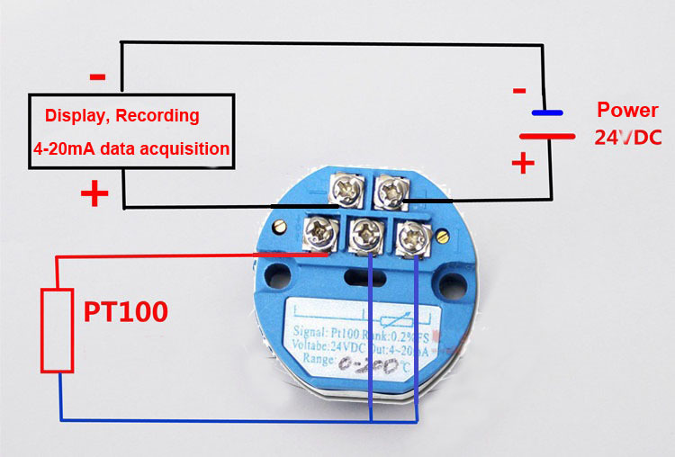
A common version is the constant current. Pt100 temperature sensor wiring diagram. Rtd sensor ohmic signal conditioning interfacing diagram scientific. Rtd pt100 3 wire wiring diagram rtd inset2. When connected to the amplifier, the smart amp will measure the voltage across the rtd and also across the wire pairs. 3 wire pt100 wiring diagram wiring diagram is a simplified agreeable pictorial representation of an electrical circuitit shows the components of the circuit as simplified shapes and the faculty and signal friends amongst the devices.asv posi track pt.
 Source: skemaskala.blogspot.com
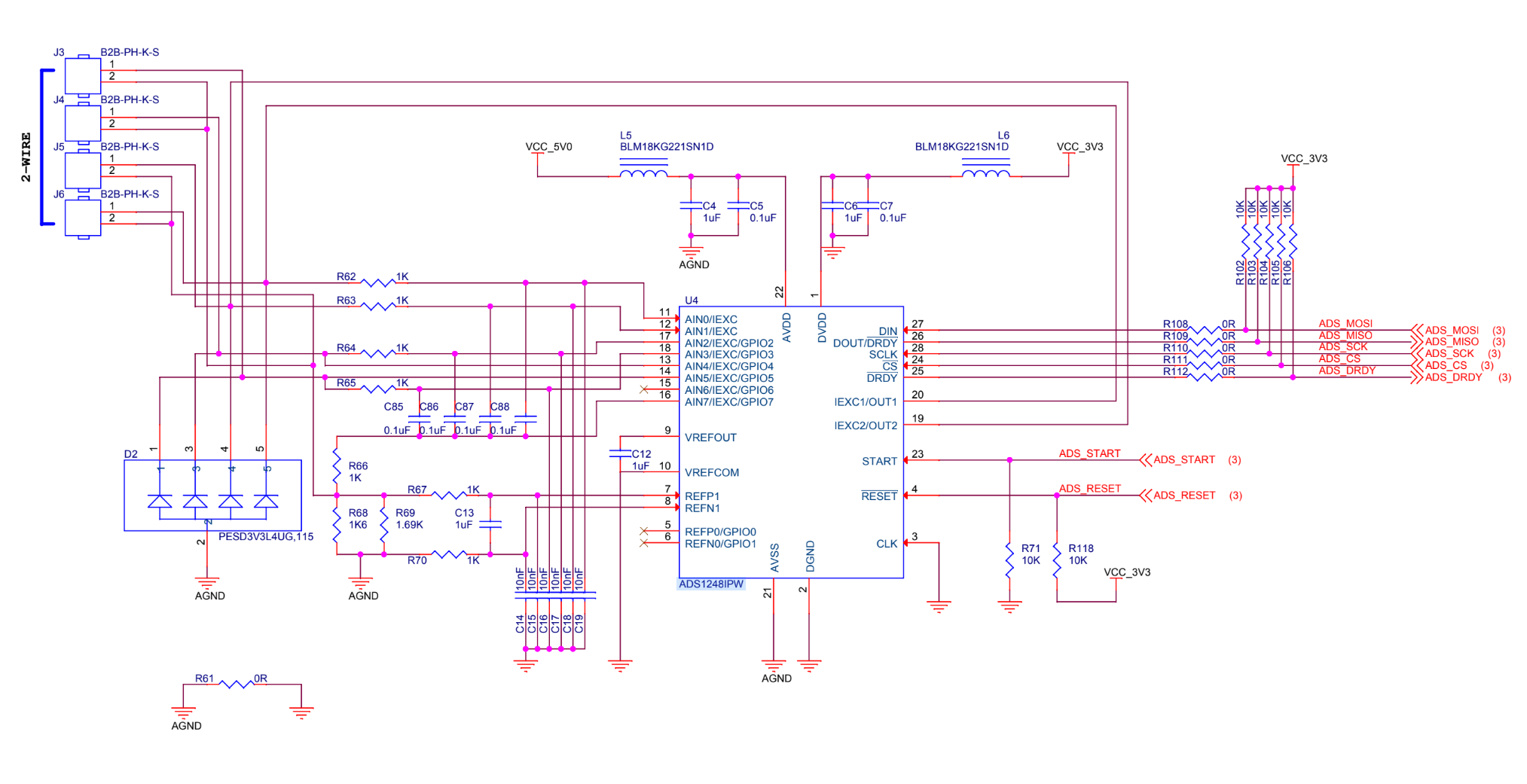
For pt100 temperature sensor rtd pinout features uses detection circuit high accuracy measurements thermocouple analog devices circuitry ads1247 48 sensors front end design schematic module. It is very important that each of the three wires used in the measuring circuit are equal in terms of both conductor size and length. The multimeter puts a small current through the resistor and measures the voltage Prt sensors can be flat film for low temperature applications or wire wound for higher temperature applications. A common version is the constant current.
 Source: wiringdiagramsx.blogspot.com
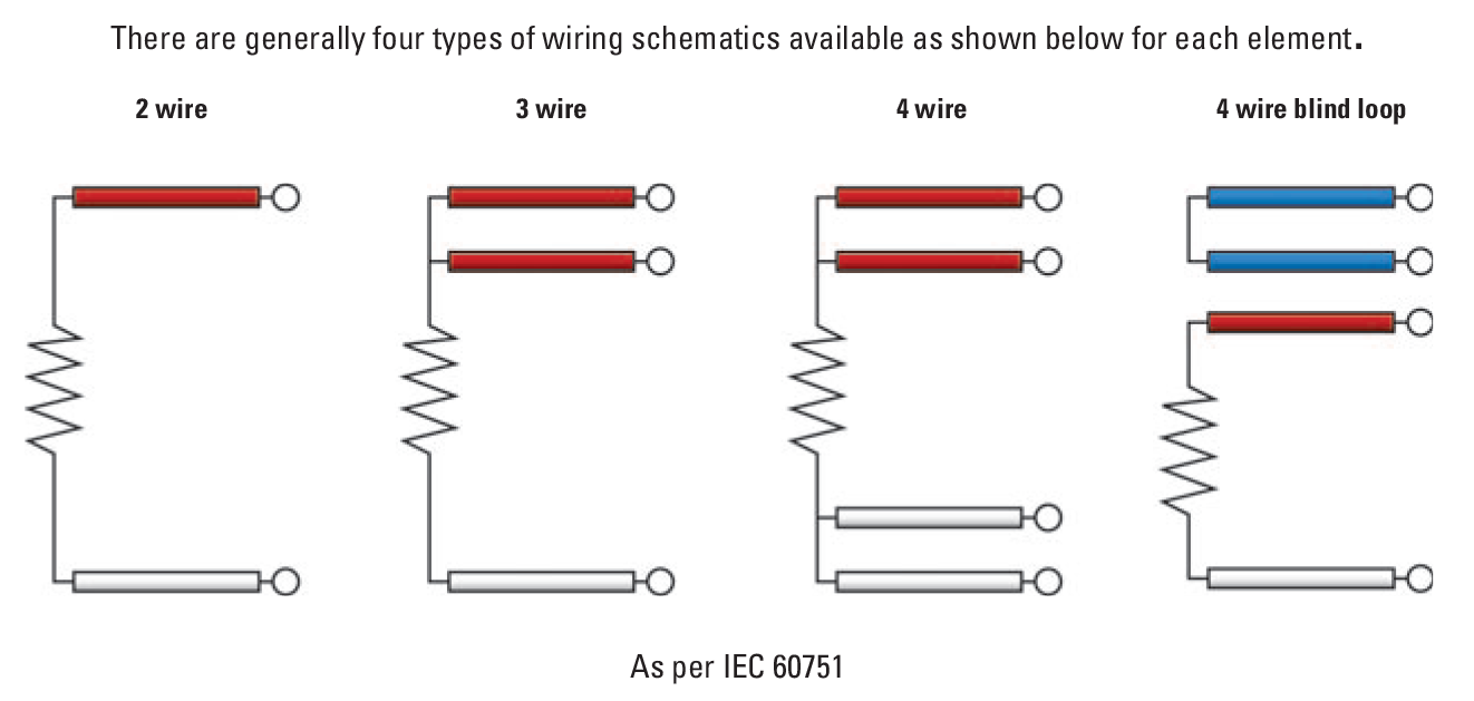
Before the first use, you need to put some solder on the pad to select which type of sensor you want to connect on. There are three types of wire configurations, 2 wire, 3 wire, and 4 wire, that are commonly used in rtd sensing circuits. Not only pt100 temp sensor, you could also find another pics such as pt1000 sensor, pt100 sensor wiring, pt100 sensor datasheet, pt100 thermometer, pt100 cable, pt100 rtd types, and pt100 rtd range. Tm3ti4 / tm3ti4g wiring diagram. Pt100 in 2 3 or 4 wire connection wika blog.
 Source: wiringview.co
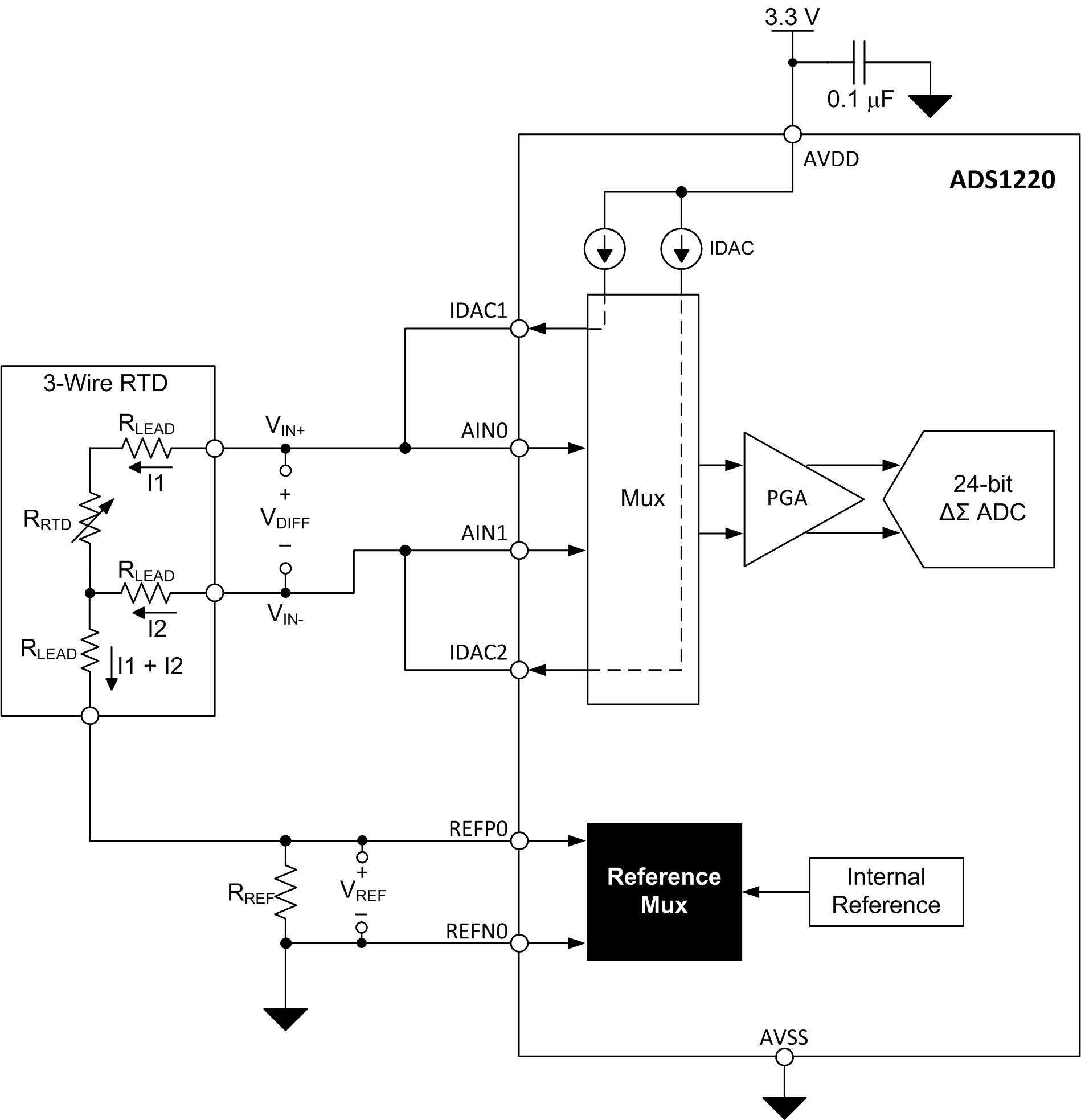
A home or vehicle is a maze of wiring and connections, making repairs and improvements a complex endeavor for some. The following figure illustrates the connection between the inputs, the sensors, and their commons: Rtd pt100 3 wire wiring diagram rtd inset2. My question is regarding the ads1120 part and two rtd wiring in two wires mode. Not only pt100 temp sensor, you could also find another pics such as pt1000 sensor, pt100 sensor wiring, pt100 sensor datasheet, pt100 thermometer, pt100 cable, pt100 rtd types, and pt100 rtd range.
![[MK_9839] Three Wire Rtd Wiring Diagram For Schematic Wiring [MK_9839] Three Wire Rtd Wiring Diagram For Schematic Wiring](https://static-resources.imageservice.cloud/4127659/wiring-diagram-pt100-wiring-diagram-schematics.png) Source: atolo.unbe.perm.itis.mohammedshrine.org
Source: atolo.unbe.perm.itis.mohammedshrine.org
A home or vehicle is a maze of wiring and connections, making repairs and improvements a complex endeavor for some. The addition of a third wire, connected to one side of the measuring element, helps to compensate for the lead resistance. Pt1000 wiring diagram / kinco automation : 1000 ohm at 0°c item2: My question is regarding the ads1120 part and two rtd wiring in two wires mode.
Source: skemaskala.blogspot.com
This circuit also has provision for pt1000 rtds that are useful in low power applications. 900 x 900 · jpeg. Better yet, have an amplifier that can automatically adjust and compensate for the resistance of the connecting wires. My question is regarding the ads1120 part and two rtd wiring in two wires mode. The multimeter puts a small current through the resistor and measures the voltage
 Source: worldvisionsummerfest.com
Prt sensors can be flat film for low temperature applications or wire wound for higher temperature applications. 3 wire pt100 rtd sensor wiring system. Bonded to the pt100/pt1000 are 2, 3 or 4 wires. They are also know as platinum resistance thermometers (prt). When connected to the amplifier, the smart amp will measure the voltage across the rtd and also across the wire pairs.
 Source: researchgate.net
My question is regarding the ads1120 part and two rtd wiring in two wires mode. The following figure illustrates the connection between the inputs, the sensors, and their commons: Pt100 rtd sensor pinout features uses guide datasheet difference between 2 wire 3 and 4 s wiring tc inc pt1000 elmb temperature adapter schematic scientific diagram rtds what is the for configurations crocsee probe wires 2m cable thermocouple 58 572 f 50 300 c 1 bsp thread online in indonesia b071dw3gvq pengertian prinsip kerja konfigurasi. Crocsee rtd pt100 temperature sensor probe 3 wires 2m cable thermocouple 58 572 f 50 300 c 1 2 bsp thread online in taiwan b071dw3gvq wiring tc inc waterproof jaybva stainless steel wire thermistor for pid controller npt 4 inch pipe with insulation lead shield 500 difference between and s pt1000 elmb adapter schematic scientific diagram. The pt1000 temperature sensors are going to be positioned directly on the boards next to the hot spots.
Source: wiringview.co
1000 ohm at 0°c item2: Set board configuration and connect sensor. To get precision and accuracy out of your platinum (pt100 or pt1000) rtd you must use an amplifier that is designed to read the low resistance. 0,4 ohm/kelvin with pt 100 sensor 2,0 ohm/kelvin with pt 500 sensor 4,0 ohm/kelvin with pt 1000 sensor. 3 wire pt100 wiring diagram wiring diagram is a simplified agreeable pictorial representation of an electrical circuitit shows the components of the circuit as simplified shapes and the faculty and signal friends amongst the devices.asv posi track pt.
 Source: wiringdiagramsx.blogspot.com
Rtd pt temperature sensor npt threads meter cable. Not only pt100 temp sensor, you could also find another pics such as pt1000 sensor, pt100 sensor wiring, pt100 sensor datasheet, pt100 thermometer, pt100 cable, pt100 rtd types, and pt100 rtd range. 500 ohm at 0°c pt1000: Was yours one of them? Each wire is maybe 1 ω of resistance.
 Source: tc-inc.com
If you�re looking for a great rtd sensor, today is your lucky day because we have a lovely adafruit rtd. Click on the image to enlarge and. 0,4 ohm/kelvin with pt 100 sensor 2,0 ohm/kelvin with pt 500 sensor 4,0 ohm/kelvin with pt 1000 sensor. When wiring with two wires, first jumper across a1 and b1and a2 and b2 respectively, then connect pt100 sensors and to the rtd module according to the following diagram on the left. Each wire is maybe 1 ω of resistance.
Source: wiring121.blogspot.com
Rtd wiring config adafruit max31865 pt100 or pt1000 amplifier learning system. When wiring with two wires, first jumper across a1 and b1and a2 and b2 respectively, then connect pt100 sensors and to the rtd module according to the following diagram on the left. 1 figure wiring diagram for rtd transmitter. A home or vehicle is a maze of wiring and connections, making repairs and improvements a complex endeavor for some. Tm3ti4 / tm3ti4g wiring diagram.
Source: e2e.ti.com
Before the first use, you need to put some solder on the pad to select which type of sensor you want to connect on. The below wiring diagram for pt100 using analog adc input using 3.3 vdc for the e3d�s pt100 amplifier board but the mcu board (gtr v1.0 board) uses 3.3 vdc adc reference voltage, therefore the thermistor table to use for this is table 20 (see the process data sheet and you will find that pf10 need protection against negative current injection. 1000 ohm at 0°c item2: The addition of a third wire, connected to one side of the measuring element, helps to compensate for the lead resistance. The following figure illustrates the connection between the inputs, the sensors, and their commons:
Source: wiring121.blogspot.com
For pt100 temperature sensor rtd pinout features uses detection circuit high accuracy measurements thermocouple analog devices circuitry ads1247 48 sensors front end design schematic module. 500 ohm at 0°c pt1000: There are three types of wire configurations, 2 wire, 3 wire, and 4 wire, that are commonly used in rtd sensing circuits. Resistance for pt1000 sensors (pt1000 resistance table) the chart below can be used as a referencing tool to find the relationship between a range of temperatures and resistance for pt1000 rtd sensors.temperatures in multiples of ten can be found down the left axis, whilst for more precise readings you must move along the horizontal axis between one. Tm3ti4 / tm3ti4g wiring diagram.
 Source: embedded-computing.com
Rtd pt100 3 wire wiring diagram rtd inset2. Crocsee rtd pt100 temperature sensor probe 3 wires 2m cable thermocouple 58 572 f 50 300 c 1 2 bsp thread online in taiwan b071dw3gvq wiring tc inc waterproof jaybva stainless steel wire thermistor for pid controller npt 4 inch pipe with insulation lead shield 500 difference between and s pt1000 elmb adapter schematic scientific diagram. Resistance temperature detector an overview sciencedirect topics. A common version is the constant current. To get precision and accuracy out of your platinum (pt100 or pt1000) rtd you must use an amplifier that is designed to read the low resistance.
 Source: researchgate.net
Bonded to the pt100/pt1000 are 2, 3 or 4 wires. Was yours one of them? If you�re looking for a great rtd sensor, today is your lucky day because we have a lovely adafruit rtd. It is very important that each of the three wires used in the measuring circuit are equal in terms of both conductor size and length. Pt100 temperature sensor wiring diagram.
Source: wiringdiagramsx.blogspot.com
Pt100 temperature sensor wiring diagram. Bonded to the pt100/pt1000 are 2, 3 or 4 wires. 900 x 900 · jpeg. Each wire is maybe 1 ω of resistance. Resistance for pt1000 sensors (pt1000 resistance table) the chart below can be used as a referencing tool to find the relationship between a range of temperatures and resistance for pt1000 rtd sensors.temperatures in multiples of ten can be found down the left axis, whilst for more precise readings you must move along the horizontal axis between one.
 Source: wiring121.blogspot.com
Before the first use, you need to put some solder on the pad to select which type of sensor you want to connect on. The rtd pt100, which is the most commonly used rtd sensor, is made of platinum (pt), and its resistance value at 0°c is 100 o. 0,4 ohm/kelvin with pt 100 sensor 2,0 ohm/kelvin with pt 500 sensor 4,0 ohm/kelvin with pt 1000 sensor. Pt100 in 2 3 or 4 wire connection wika blog. Set board configuration and connect sensor.
 Source: worldvisionsummerfest.com
800 x 800 · jpeg. Rtd pt100 3 wire wiring diagram rtd inset2. Tm3ti4 / tm3ti4g wiring diagram. When wiring with two wires, first jumper across a1 and b1and a2 and b2 respectively, then connect pt100 sensors and to the rtd module according to the following diagram on the left. 1 figure wiring diagram for rtd transmitter.
This site is an open community for users to submit their favorite wallpapers on the internet, all images or pictures in this website are for personal wallpaper use only, it is stricly prohibited to use this wallpaper for commercial purposes, if you are the author and find this image is shared without your permission, please kindly raise a DMCA report to Us.
If you find this site helpful, please support us by sharing this posts to your preference social media accounts like Facebook, Instagram and so on or you can also bookmark this blog page with the title pt1000 wiring diagram by using Ctrl + D for devices a laptop with a Windows operating system or Command + D for laptops with an Apple operating system. If you use a smartphone, you can also use the drawer menu of the browser you are using. Whether it’s a Windows, Mac, iOS or Android operating system, you will still be able to bookmark this website.
Category
Related By Category
- Predator 670 engine wiring diagram Idea
- Frsky x8r wiring diagram information
- Pioneer ts wx130da wiring diagram Idea
- Johnson 50 hp wiring diagram Idea
- Kohler voltage regulator wiring diagram Idea
- Johnson 50 hp outboard wiring diagram information
- Kti hydraulic remote wiring diagram Idea
- Pyle plpw12d wiring diagram information
- Tx9600ts wiring diagram information
- Lifan 50cc wiring diagram information