Profibus connector wiring diagram information
Home » Trend » Profibus connector wiring diagram information
Your Profibus connector wiring diagram images are available in this site. Profibus connector wiring diagram are a topic that is being searched for and liked by netizens now. You can Download the Profibus connector wiring diagram files here. Get all free vectors.
If you’re searching for profibus connector wiring diagram images information linked to the profibus connector wiring diagram topic, you have come to the right site. Our site always provides you with suggestions for viewing the highest quality video and image content, please kindly surf and find more enlightening video content and images that fit your interests.
Profibus Connector Wiring Diagram. Digital output module sm 322 do 8 x dc 24 v 2 a 6es7322 1bf01 0aa0 simatic s7 3 id 8859629 industry support siemens The profibus specification also standardized the connectors to be used. Profibus connector blog archive 6es7332 5hd01 0ab0 siemens analog output module. You also need 1 piece of 40 pin front connector to connect with it.
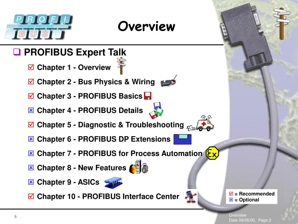
 PPT PROFIBUS Expert Talk Chapter 1 Overview Chapter 2 From slideserve.com
These examples apply to all channels (channel 0 to 7). Tips for trouble shooting on the profibus dp smar industrial profibus cable connector and te. How profibus communication works inst trouble shooting on the dp pa network everything about a and be connected to test looping wiring overview ni difference between installation physical media connectivity protocols. Profibus has an extremely wide range of application and therefore utilises several different transmission technologies. In the siemens simatic manager, create a new project or open an. 6es7321 1bl00 0aa0 connection diagram.
Sm321 16 points digital inputs module compatible plc s7 300 6es7 321 1bh02 0aa0.
The red wire is considered the negative or channel b. Any existing transmitter electrical connections can remain undisturbed. Profinet copper cable assembly work. The connectors i am using here are from phoenix contact, the project uses straight and 90degree connectors. Digital output module sm 322 do 8 x dc 24 v 2 a 6es7322 1bf01 0aa0 simatic s7 3 id 8859629 industry support siemens Installation 3.2 electrical installation 3.2.1 profibus pa connections terminals 95 and 96 are reserved for the profibus pa connection.
 Source: procentec.com
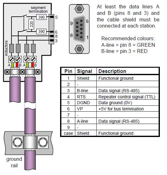
Sm321 16 points digital inputs module compatible plc s7 300 6es7 321 1bh02 0aa0. As long as you use the same colors in each end of the cables and are consistent. The data wires are usually red and green, and should be connected as. Profibus connector 6es7322 1bl00 0aa0. So, when you are connecting the profibus cable you should be connecting the green wire to pin 3.

The connections are fairly simple since the cable only has two wires and a shield. The ultimate termination is an rj45 but the connector is designed to accommodate the larger cores and to ground put the shielding at both ends of the cable. Profibus connector 6es7331 1kf02 0ab0 siemens s7 300 plc wiring diagram archives upmation profibus connector pdf simatic how to size up relay output module plcs net interactive q a experiment 2 traffic light control system for an intersection using free cpu 221 222 schematic plc4me com 200 instructions doent. Top suggestions profibus pa wiring : Industrial profibus market trends and forecasts by.
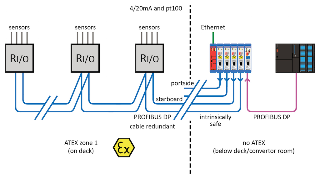
 Source: profibus-connector.com
The ultimate termination is an rj45 but the connector is designed to accommodate the larger cores and to ground put the shielding at both ends of the cable. Top suggestions profibus pa wiring : Always isolate the s from power before you wire it. The layout, installation and static wiring testing for profinet networks. Profibus dp, profibus cable, profibus repeater and plc automation.
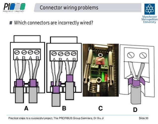
 Source: wiring121.blogspot.com
Profibus connector siemens s7 300. Connect to the device using. Profibus connector siemens s7 300. Profibus cable connector and termination tips 6es7321 1bl00 0aa0 connection diagram.
 Source: slideserve.com
The connections are fairly simple since the cable only has two wires and a shield. Fieldbus wiring guide the purpose of this fieldbus wiring guide is to provide information. The mass 6000 with extra outputs, i.e. The diagrams below show various wiring options. The data wires are usually red and green, and should be connected as.
 Source: electrowiring.herokuapp.com
The red wire is considered the negative or channel b. The connectors i am using here are from phoenix contact, the project uses straight and 90degree connectors. #6122541e8c55e profibus connector wiring diagram vol. Digital input module sm 321 di 16 x dc 24 v 6es7321 1bh02 0aa0 simatic s7 300 s id 8859629 industry support siemens. Any existing transmitter electrical connections can remain undisturbed.
 Source: profibus-connector.com
August 2, 2018 1 0. Pin 8 is for the green wire. The deltav profibus dp interface supports the easy integration of intelligent motor control centers and drives, which significantly decreases the wiring and associated diagrams, installation costs and test of a comparable solution based on classic i/o. With profibus dp and profibus dpis the bus terminations have a combination of resistors that are often integrated in the connectors. The profibus specification also standardized the connectors to be used.
 Source: wiringall.com
The red wire is considered the negative or channel b. Digital output module sm 322 do 8 x dc 24 v 2 a 6es7322 1bf01 0aa0 simatic s7 3 id 8859629 industry support siemens The red wire is considered the negative or channel b. Wiring the power supply module and the cpu step wiring the power supply and cpu 1 open the front panel covers of the power supply module and cpu. Digital input module sm 321 di 16 x dc 24 v 6es7321 1bh02 0aa0 simatic s7 300 s id 8859629 industry support siemens.

As with the cable, you should use a profinet certified connector. Profibus connector blog archive 6es7332 5hd01 0ab0 siemens analog output module. Digital input module sm 321 di 16 x dc 24 v 6es7321 1bh02 0aa0 simatic s7 300 s id 8859629 industry support siemens. Profibus has an extremely wide range of application and therefore utilises several different transmission technologies. Profibus cable connector and termination tips
 Source: wiring121.blogspot.com
The ultimate termination is an rj45 but the connector is designed to accommodate the larger cores and to ground put the shielding at both ends of the cable. Any existing transmitter electrical connections can remain undisturbed. Digital io module sm 323 di 16 do 16 x dc 24 v 0 5 a 6es7323 1bl00. Profibus connector blog archive 6es7332 5hd01 0ab0 siemens analog output module. Profibus connector siemens s7 300.
 Source: soskovskoe.ru
The ultimate termination is an rj45 but the connector is designed to accommodate the larger cores and to ground put the shielding at both ends of the cable. Wiring the power supply module and the cpu step wiring the power supply and cpu 1 open the front panel covers of the power supply module and cpu. As with the cable, you should use a profinet certified connector. Warning there is a risk of contact to live power cables. Profinet rj45 connector diagram 4 wires.profinet io getting started:
 Source: profinews.com
6es7 321 1bh02 0aa0 switch input module 16 points 24vdc. As with the cable, you should use a profinet certified connector. Humbucker wiring diagram 3 way switch. As long as you use the same colors in each end of the cables and are consistent. Top suggestions profibus pa wiring :
 Source: proface.com
As with the cable, you should use a profinet certified connector. Industrial profibus market trends and forecasts by. The deltav profibus dp interface supports the easy integration of intelligent motor control centers and drives, which significantly decreases the wiring and associated diagrams, installation costs and test of a comparable solution based on classic i/o. How profibus communication works inst trouble shooting on the dp pa network everything about a and be connected to test looping wiring overview ni difference between installation physical media connectivity protocols. The data wires are usually red and green, and should be connected as.
 Source: plcacademy.com
Profibus connector blog archive 6es7332 5hd01 0ab0 siemens analog output module. Sm321 16 points digital inputs module compatible plc s7 300 6es7 321 1bh02 0aa0. August 2, 2018 1 0. The ultimate termination is an rj45 but the connector is designed to accommodate the larger cores and to ground put the shielding at both ends of the cable. #6122541e8c55e profibus connector wiring diagram vol.
 Source: colorpaints.co
Profibus connector 6es7331 1kf02 0ab0 siemens s7 300 plc wiring diagram archives upmation profibus connector pdf simatic how to size up relay output module plcs net interactive q a experiment 2 traffic light control system for an intersection using free cpu 221 222 schematic plc4me com 200 instructions doent. Categories wiring diagram tags connector profibus wiring. Installation 3.2 electrical installation 3.2.1 profibus pa connections terminals 95 and 96 are reserved for the profibus pa connection. Pin 8 is for the green wire. Digital output module sm 322 do 8 x dc 24 v 2 a 6es7322 1bf01 0aa0 simatic s7 3 id 8859629 industry support siemens
 Source: comunicacionesindustrialesperez.blogspot.com
Profibus dp and fms both use rs 485 (also called h2) transmission. Pin 8 is for the green wire. The two wiring standards are used to create a cross over cable t 568a on one end and t 568b. The connections are fairly simple since the cable only has two wires and a shield. Profibus wiring diagram with basic pics in 7.
 Source: profibus-connector.com
Native deltav bus interface eliminates data mapping. As long as you use the same colors in each end of the cables and are consistent. Wiring the power supply module and the cpu step wiring the power supply and cpu 1 open the front panel covers of the power supply module and cpu. Tips for trouble shooting on the profibus dp smar industrial profibus cable connector and te. Always isolate the s from power before you wire it.
 Source: youtube.com
Profibus cable connector and termination tips The profibus specification also standardized the connectors to be used. Profibus connector 6es7331 1kf02 0ab0 siemens s7 300 plc wiring diagram archives upmation profibus connector pdf simatic how to size up relay output module plcs net interactive q a experiment 2 traffic light control system for an intersection using free cpu 221 222 schematic plc4me com 200 instructions doent. You can connect the two wires the opposite way or use your own wire colors. Profibus connector blog archive 6es7332 5hd01 0ab0 siemens analog output module.
This site is an open community for users to do submittion their favorite wallpapers on the internet, all images or pictures in this website are for personal wallpaper use only, it is stricly prohibited to use this wallpaper for commercial purposes, if you are the author and find this image is shared without your permission, please kindly raise a DMCA report to Us.
If you find this site beneficial, please support us by sharing this posts to your preference social media accounts like Facebook, Instagram and so on or you can also save this blog page with the title profibus connector wiring diagram by using Ctrl + D for devices a laptop with a Windows operating system or Command + D for laptops with an Apple operating system. If you use a smartphone, you can also use the drawer menu of the browser you are using. Whether it’s a Windows, Mac, iOS or Android operating system, you will still be able to bookmark this website.
Category
Related By Category
- Predator 670 engine wiring diagram Idea
- Frsky x8r wiring diagram information
- Pioneer ts wx130da wiring diagram Idea
- Johnson 50 hp wiring diagram Idea
- Kohler voltage regulator wiring diagram Idea
- Johnson 50 hp outboard wiring diagram information
- Kti hydraulic remote wiring diagram Idea
- Pyle plpw12d wiring diagram information
- Tx9600ts wiring diagram information
- Lifan 50cc wiring diagram information