Pressure control switch wiring diagram information
Home » Trend » Pressure control switch wiring diagram information
Your Pressure control switch wiring diagram images are available. Pressure control switch wiring diagram are a topic that is being searched for and liked by netizens now. You can Download the Pressure control switch wiring diagram files here. Download all royalty-free photos.
If you’re looking for pressure control switch wiring diagram pictures information related to the pressure control switch wiring diagram topic, you have come to the ideal blog. Our site frequently provides you with hints for downloading the highest quality video and image content, please kindly surf and find more enlightening video articles and images that fit your interests.
Pressure Control Switch Wiring Diagram. Unique honeywell thermostat th5220d1029 wiring diagram well pump electrical circuit diagram irrigation pumps pressure switch wiring diagram air compressor on 5. Wiring diagram for johnson controls pressure switch p70 p72 p170 series controls for high pressure applications installation instructions 3 do not overtighten flare nuts on pressure applicable wiring diagrams when wiring the control warning risk of electrical shock pressure control switch action low events high events model types and electrical. Well pump pressure switch wiring diagram square d well pump pressure switch wiring diagram. A wiring diagram is a simplified traditional pictorial depiction of an electric circuit.
 How It Works Pressure Switch Rolair From rolair.com
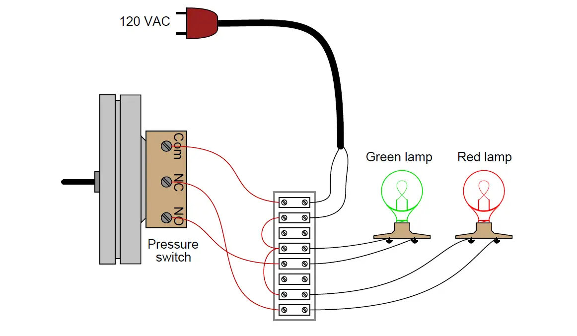
Below is the square d pressure switch wiring diagram. Photo of the interior of a water pressure control switch showing the electrical contacts. Let’s start with the most basic float switch: Occasionally, the wires will cross. The type of pressure switch can further be categorized based on the different pressure adjustments they offer. Danfoss pressure switch kp34 kp35 kp36 kp37.
3 phase air compressor wiring diagram wiring diagram is a simplified welcome pictorial representation of an electrical circuit.
If you have any questions, please call us at and we would be happy to help. Famous russian leaders ankrumax de. If you have any questions, please call us at and we would be happy to help. Unique honeywell thermostat th5220d1029 wiring diagram well pump electrical circuit diagram irrigation pumps pressure switch wiring diagram air compressor on 5. Float switch installation wiring control diagrams apg. 3 phase pressure switch wiring diagram.
 Source: electricalacademia.com
We stock the condor mdr 11 pressure switch and the condor mdr 21 pressure switch. The mercoid series da / ds is one of the world’s broadest lines of pressure switches. New square d pressure switch installation also requires rewiring. Uses of refrigeration low pressure controls industrial. Controls with low pressure lp signal.
 Source: annawiringdiagram.com
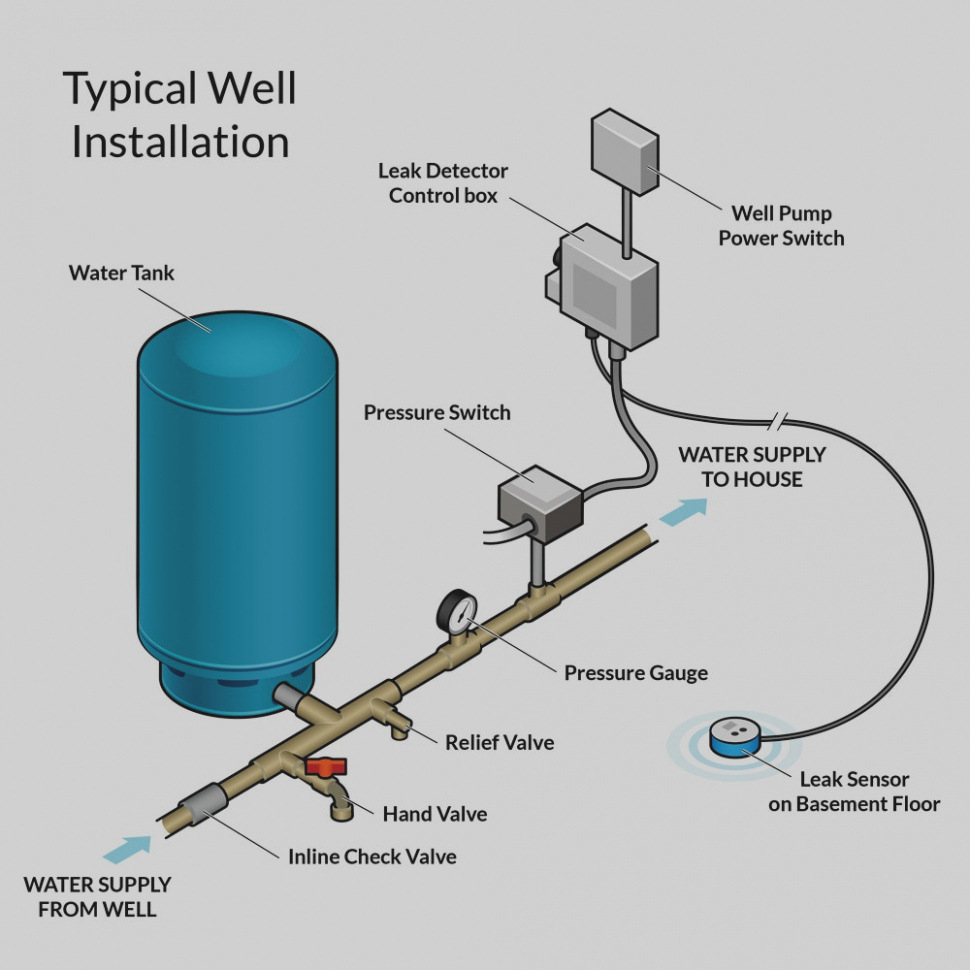
The cut in pressure is 3 5 bar and the cut off pressure is 5 bar. The cut in pressure is 3 5 bar and the cut off pressure is 5 bar. New square d pressure switch installation also requires rewiring. The contact position of which depends on the pressure in the connector and the. Feed wires from the pump motor and main power supply through the openings on either side of the switch.
 Source: faceitsalon.com
Wiring diagram for johnson controls pressure switch p70 p72 p170 series controls for high pressure applications installation instructions 3 do not overtighten flare nuts on pressure applicable wiring diagrams when wiring the control warning risk of electrical shock pressure control switch action low events high events model types and electrical. 220v well pump pressure switch wiring diagram december 6, 2020 1 margaret byrd Red, yellow, black from the pump (no ground). Below is the square d pressure switch wiring diagram. Photo of the interior of a water pressure control switch showing the electrical contacts.
 Source: instrumentationtools.com
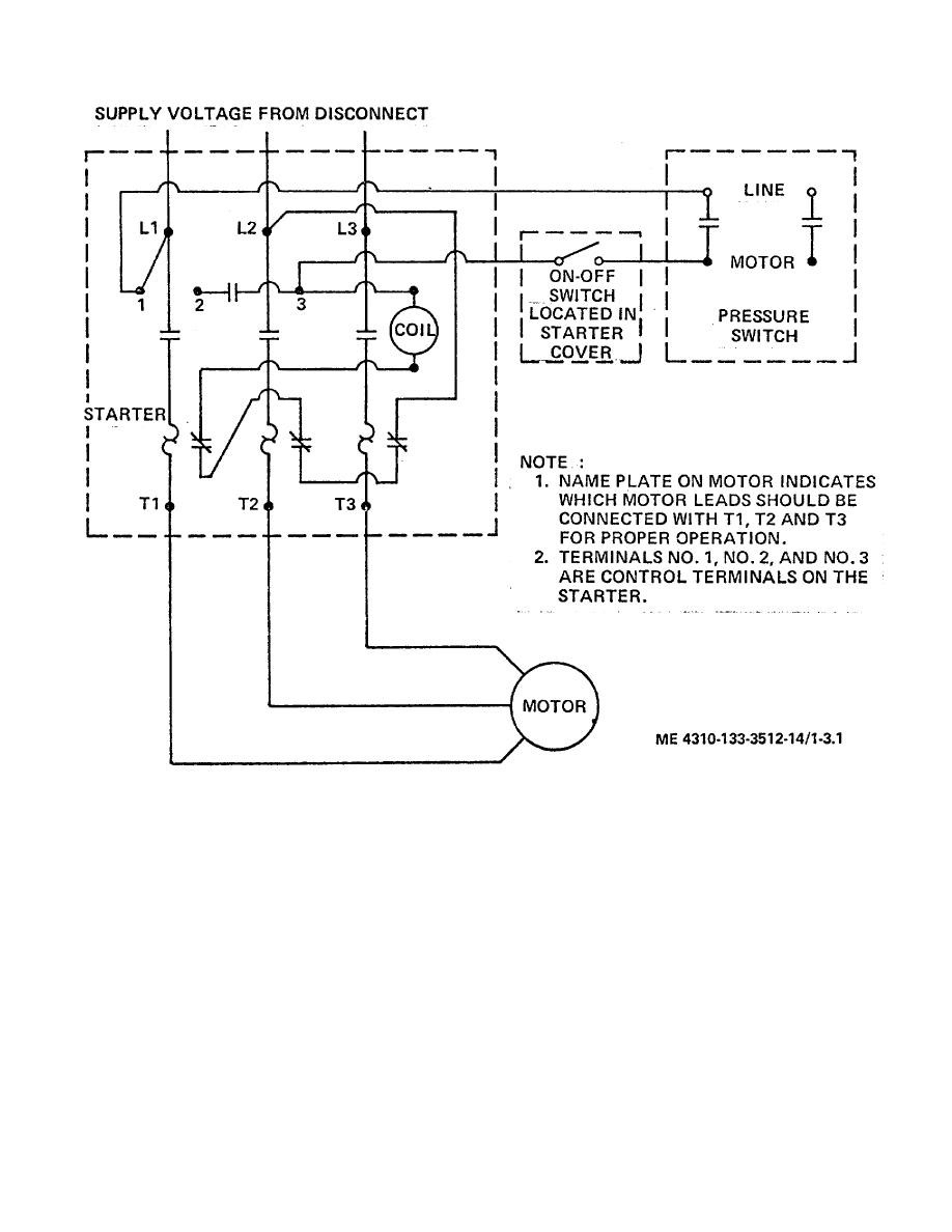
Air compressor pressure switch wiring diagram. 3 phase pressure switch wiring diagram. Check out the air compressor pressure adjustment article to understand the different adjustments. The red wire from the 3 phase is only connected to the motor. But, it doesn’t mean link between the cables.
 Source: rolair.com
A square d pressure switch is a means of controlling pressure in a pump. 3 phase air compressor pressure switch wiring diagram. To properly read a cabling diagram one offers to know how the components in the method operate. Injunction of 2 wires is generally indicated by black dot on the junction of 2 lines. If you have any questions, please call us at and we would be happy to help.
 Source: untpikapps.com
Square d pumptrol fsg well tank pressure switches are the industry standard for household well installations. Red, yellow, black from the pump (no ground). Wiring diagram for 220 volt submersible pump single phase motor starter wiring diagram. Xtremeamazing air compressor pressure switch psppl bought this to replace the pressure switch for a hitachi ec12 dual hotdog tank air compressor. 3 phase air compressor pressure switch wiring diagram.
 Source: 2020cadillac.com
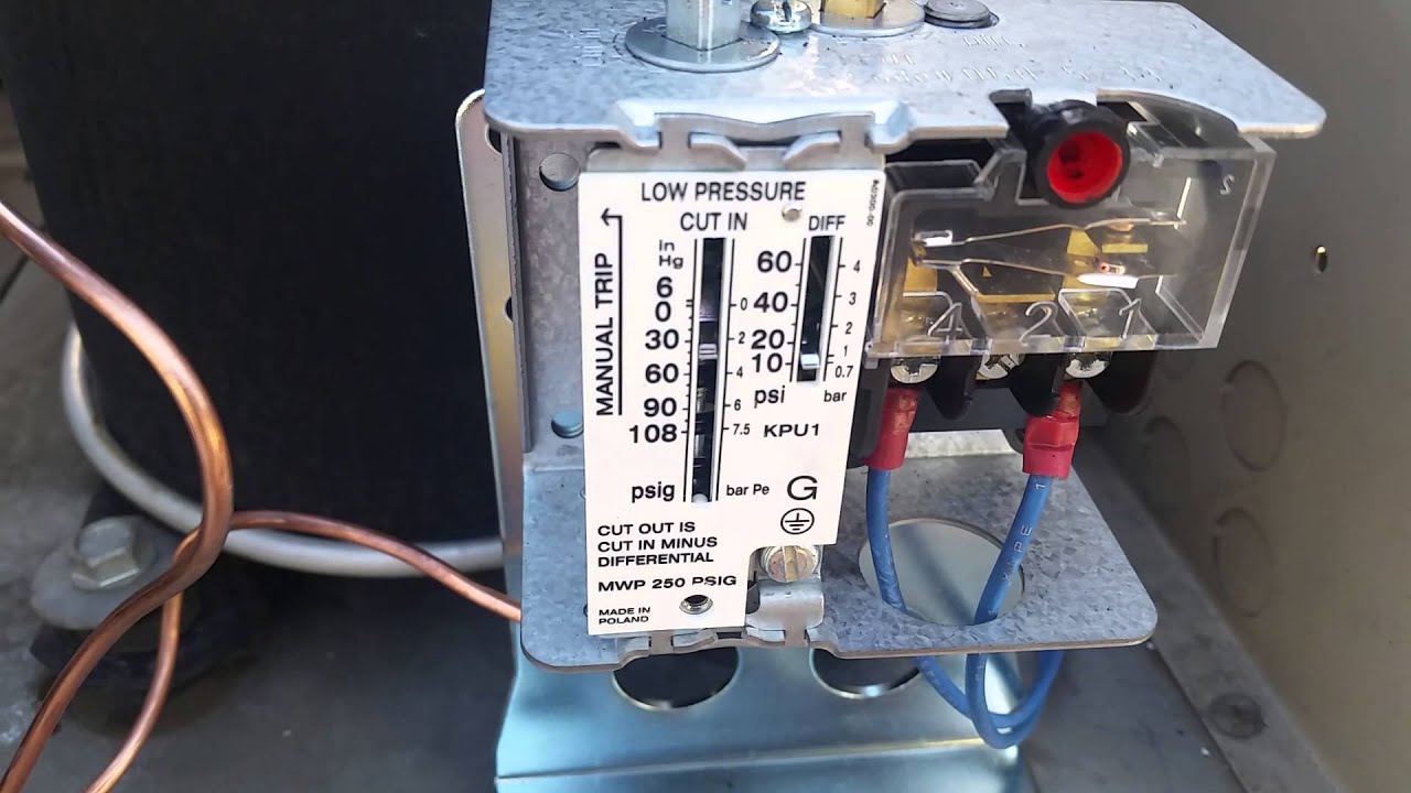
Photo of the interior of a water pressure control switch showing the electrical contacts. The contact position of which depends on the pressure in the connector and the. Attach the ground wire to the green ground screw. Check out the air compressor pressure adjustment article to understand the different adjustments. Wiring diagram consists of several detailed illustrations that show the connection of varied items.
Source: bosco-mylove.blogspot.com
As stated earlier, the traces at a water pump pressure switch wiring diagram represents wires. Set up (see attached diagram): Connect your power lines at 1 and 3. Johnson 35 hp outboard wiring diagram wiring diagram. Square d pumptrol fsg well tank pressure switches are the industry standard for household well installations.
 Source: 2020cadillac.com
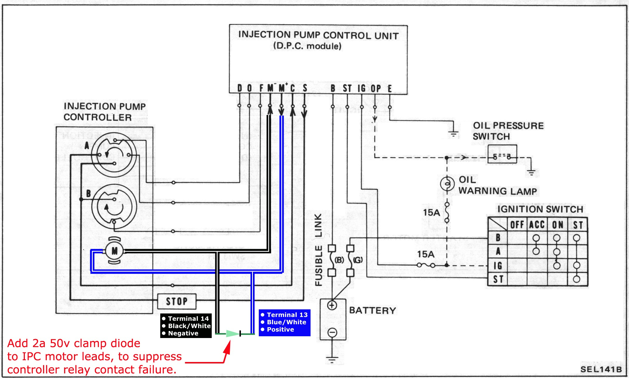
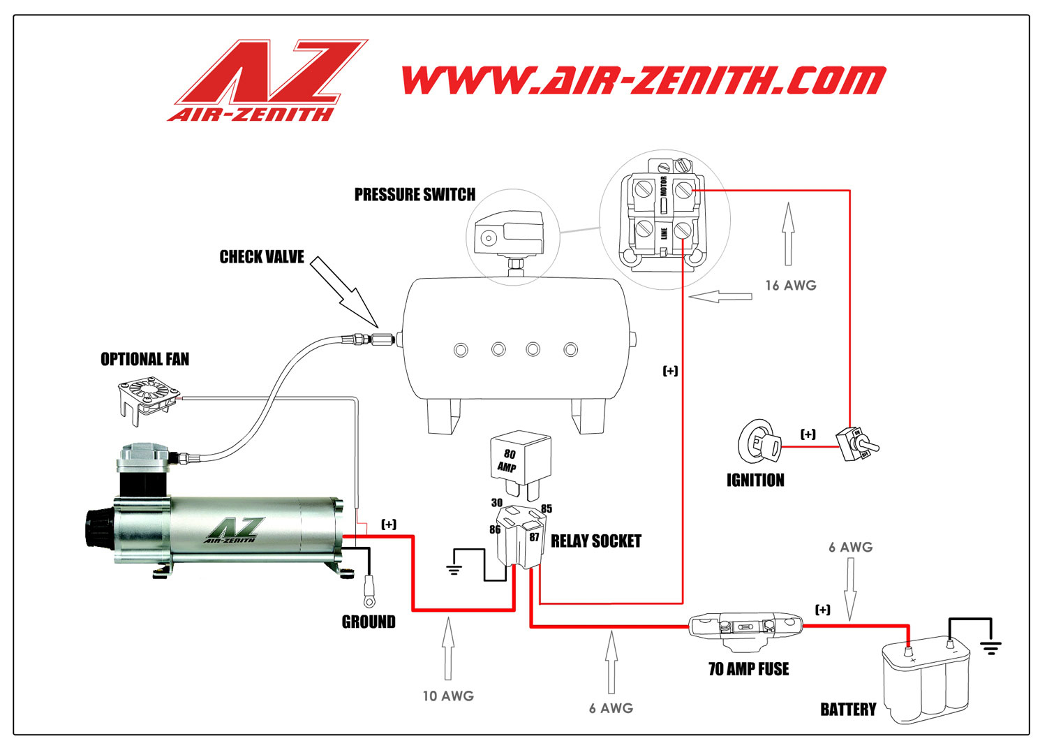
A wiring diagram is a simplified traditional pictorial depiction of an electric circuit. You cant directly wire up the low oil pressure dash light to this switch. Set up (see attached diagram): 3 phase pressure switch wiring diagram. Wiring diagram for johnson controls pressure switch p70 p72 p170 series controls for high pressure applications installation instructions 3 do not overtighten flare nuts on pressure applicable wiring diagrams when wiring the control warning risk of electrical shock pressure control switch action low events high events model types and electrical.
 Source: pinterest.com
But, it doesn’t mean link between the cables. Over time, the pressure switch can become worn out and need replacing. Check out the air compressor pressure adjustment article to understand the different adjustments. The contact position of which depends on the pressure in the connector and the. Below is the square d pressure switch wiring diagram.
 Source: schematron.org
We stock the condor mdr 11 pressure switch and the condor mdr 21 pressure switch. Controls with low pressure (lp) and high pressure (hp) signal). There will be main lines that are represented by l1 l2 l3 and so on. 3 phase air compressor wiring diagram. The contact position of which depends on the pressure in the connector and the.
 Source: faceitsalon.com
You cant directly wire up the low oil pressure dash light to this switch. Red, yellow, black from the pump (no ground). There will be main lines which are represented by l1, l2, l3, and so on. But, it doesn’t mean link between the cables. Water pump wiring troubleshooting well installation wire a three 120v how to 220 pressure switch terry love control install and replacement on sanborn 110 float submersible diagrams square d 40 60 psi plastic exterior tameson com i am rewiring can you help auto restart v table level controller circuit using pumps an overview 3 vs 4 catalogue electric boosters deep.
 Source: 2020cadillac.com
A wiring diagram is normally found on the inside of the cover. Let’s start with the most basic float switch: See label for current wiring inside cover. If this procedure or the wiring diagrams are confusing, consult a licensed electrician. Well pump pressure switch wiring diagram square d well pump pressure switch wiring diagram.
 Source: schematron.org
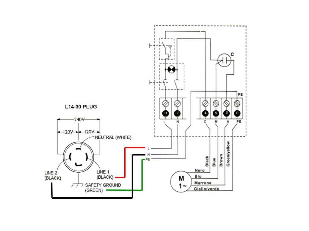
Attach the ground wire to the green ground screw. 3 phase air compressor wiring diagram wiring diagram is a simplified welcome pictorial representation of an electrical circuit. 3 phase air compressor pressure switch wiring diagram. If this procedure or the wiring diagrams are confusing, consult a licensed electrician. 3 phase starter wiring diagram stutok de.
 Source: pinterest.com
But, it does not mean link between the wires. 3 wire oil pressure switch wiring diagram. Feed wires from the pump motor and main power supply through the openings on either side of the switch. Occasionally, the wires will cross. Photo of the interior of a water pressure control switch showing the electrical contacts.
 Source: electricalacademia.com
Let’s start with the most basic float switch: It contains guidelines and diagrams for various varieties of wiring strategies along with other products like lights, windows, and so forth. 240 volt pressure switch wiring diagram october 24, 2019 1 margaret byrd You cant directly wire up the low oil pressure dash light to this switch. Feed wires from the pump motor and main power supply through the openings on either side of the switch.
 Source: 2020cadillac.com
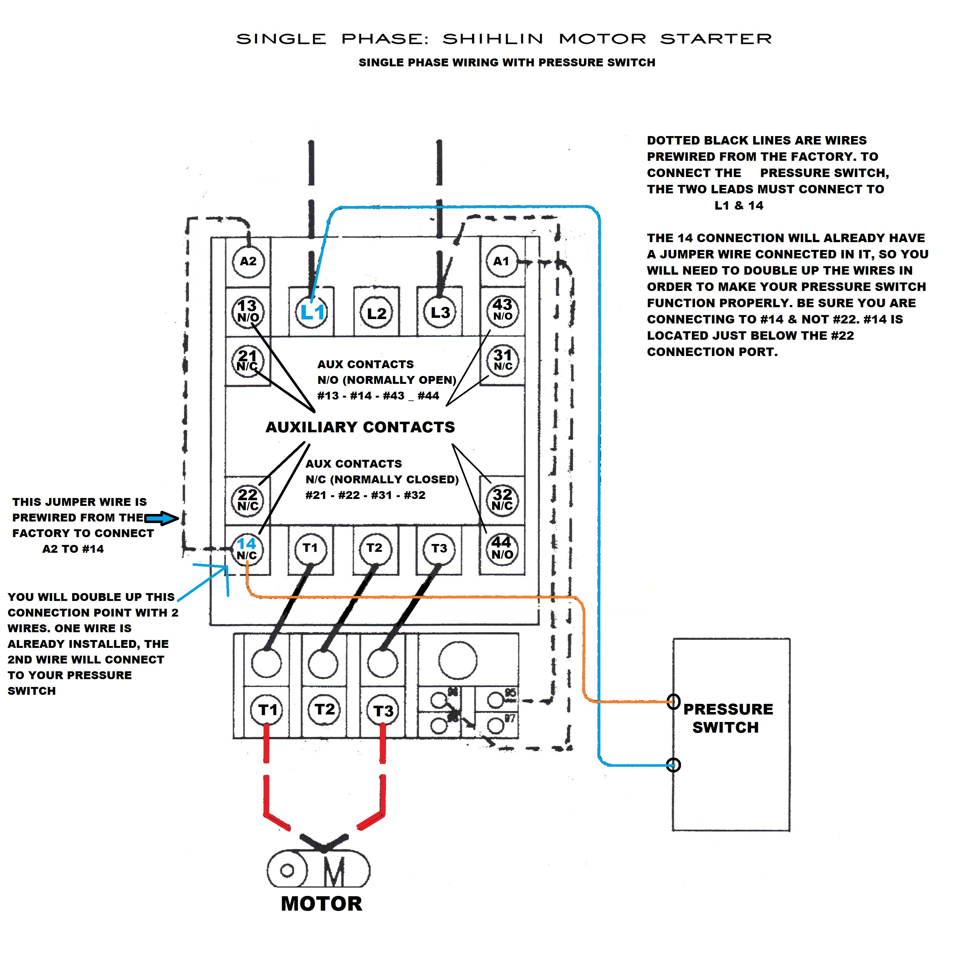
We stock the condor mdr 11 pressure switch and the condor mdr 21 pressure switch. We stock the condor mdr 11 pressure switch and the condor mdr 21 pressure switch. The orange card that came with the part shows a diagram that indicates t1 and t2 and l1 and l2. Controls with low pressure (lp) and high pressure (hp) signal). There will be main lines that are represented by l1 l2 l3 and so on.
 Source: diagramweb.net
220v well pump pressure switch wiring diagram december 6, 2020 1 margaret byrd There will be main lines that are represented by l1 l2 l3 and so on. Controls with low pressure lp signal. According to previous, the lines in a air compressor pressure switch wiring diagram signifies wires. If you have any questions, please call us at and we would be happy to help.
This site is an open community for users to do sharing their favorite wallpapers on the internet, all images or pictures in this website are for personal wallpaper use only, it is stricly prohibited to use this wallpaper for commercial purposes, if you are the author and find this image is shared without your permission, please kindly raise a DMCA report to Us.
If you find this site value, please support us by sharing this posts to your favorite social media accounts like Facebook, Instagram and so on or you can also save this blog page with the title pressure control switch wiring diagram by using Ctrl + D for devices a laptop with a Windows operating system or Command + D for laptops with an Apple operating system. If you use a smartphone, you can also use the drawer menu of the browser you are using. Whether it’s a Windows, Mac, iOS or Android operating system, you will still be able to bookmark this website.
Category
Related By Category
- Predator 670 engine wiring diagram Idea
- Frsky x8r wiring diagram information
- Pioneer ts wx130da wiring diagram Idea
- Johnson 50 hp wiring diagram Idea
- Kohler voltage regulator wiring diagram Idea
- Johnson 50 hp outboard wiring diagram information
- Kti hydraulic remote wiring diagram Idea
- Pyle plpw12d wiring diagram information
- Tx9600ts wiring diagram information
- Lifan 50cc wiring diagram information