Powerflex 753 wiring diagrams information
Home » Trending » Powerflex 753 wiring diagrams information
Your Powerflex 753 wiring diagrams images are ready. Powerflex 753 wiring diagrams are a topic that is being searched for and liked by netizens today. You can Find and Download the Powerflex 753 wiring diagrams files here. Get all free images.
If you’re looking for powerflex 753 wiring diagrams images information related to the powerflex 753 wiring diagrams interest, you have pay a visit to the ideal site. Our site frequently provides you with hints for viewing the maximum quality video and image content, please kindly hunt and find more enlightening video content and images that match your interests.
Powerflex 753 Wiring Diagrams. Powerflex 525 vfd setup programming parameters wiring diagram rslogix studio 5000 ethernet ip address start stop powerflex 753 variable frequency motor manualzz allen bradley powerflex 753 30 hp customized vfd package atlas electric Literature library | rockwell automation By rachal waananen | july 14, 2018. Allen bradley low voltage ac drives powerflex 753 architecture manufacturer from gurgaon.
 Allen Bradley Vfd Powerflex 753 Wiring Diagram Wiring From wiringdiagram.2bitboer.com
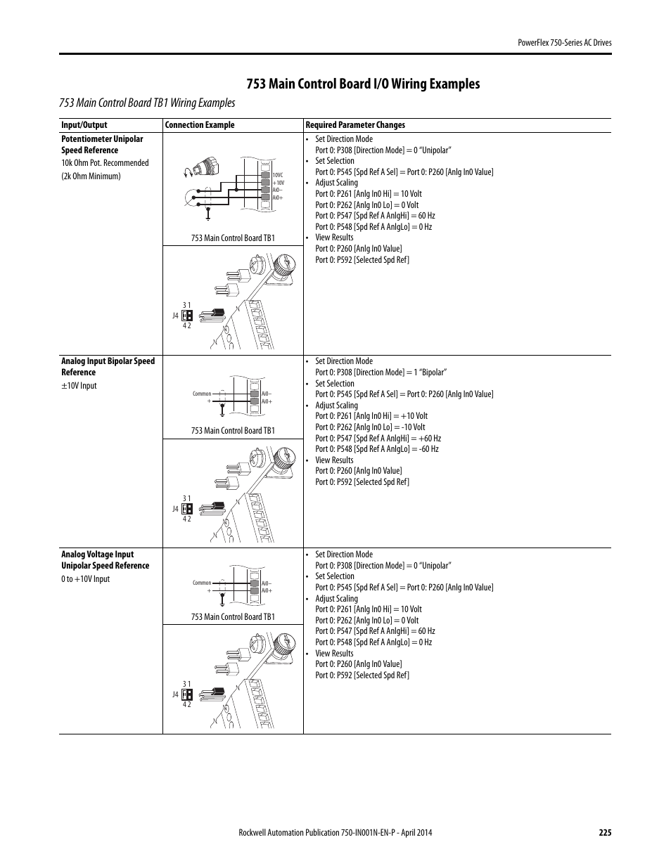
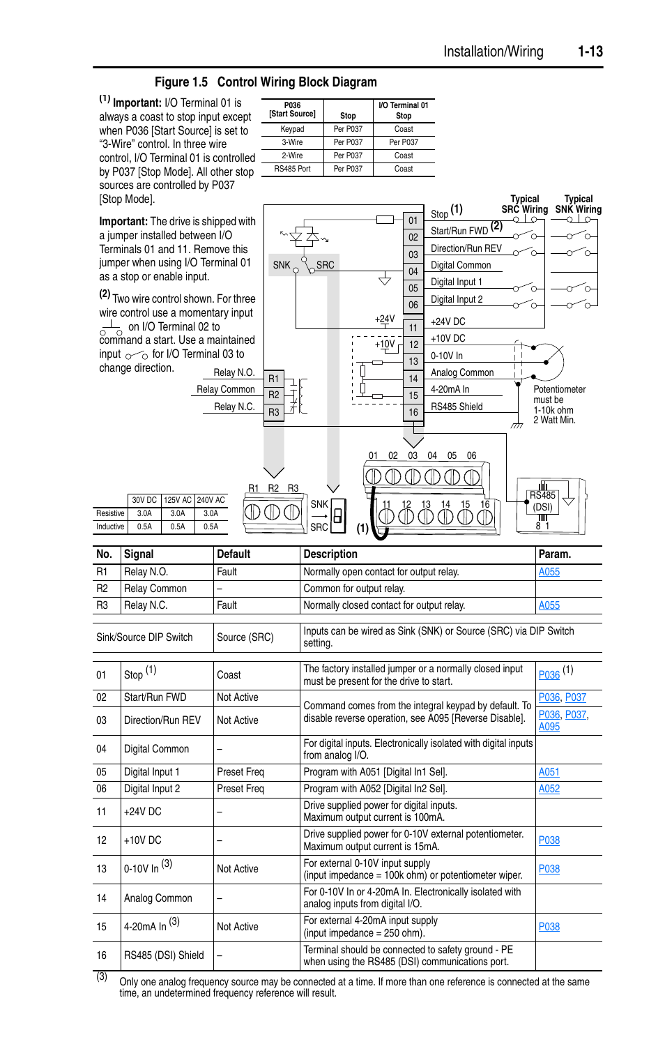
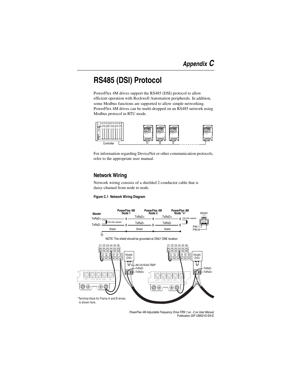
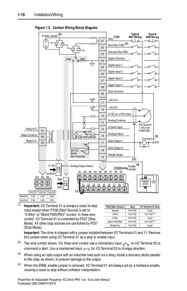
The examples and diagrams in this manual are included. Note the fault code in the telemetry user inteface. Table 1.l 753 main control board details no. Allen bradley powerflex vfd 700 to 750 753 drive 525 setup programming 40 ac drives parameter input and run off 110 for configuration low voltage rockwell automation modernization part iii 1305 adjule frequency 30 hp series not seeing digital inputs manual ppt 4m quick start. On powerflex 753 wiring diagram. There is an enable input on the main board.
Powerflex 753 main control board.
Drive modernization part v powerflex 700 to 750 horizon solutions allen bradley vfd instrumentationtools vi 40 525 setup programming parameters wiring diagram rslogix studio 5000 ethernet ip address start stop 753 main control board i o examples tb1 rockwell. On intex pure spa control base wiring diagram powerflex 753 wiring diagram; Power supply for internal cooling fan (frames 2 & 3). Powerflex 525 vfd setup programming parameters wiring diagram rslogix studio 5000 ethernet ip address start stop drive modernization part vi powerflex 40 to 525 horizon solutions powerflex 753 ac drives allen bradley united states Presently you are looking with regard to an powerflex 753 wiring diagram example of which we provide here inside some kind of document formats many of these as pdf, doc, energy point, and in addition images of which will make it simpler for you to create an powerflex 753 wiring diagram yourself. Note that although this method is simple, it’s not the recommended way to use these drives.
 Source: wiringdiagram.2bitboer.com
Turn all vfd’s off via the telemetry user interface. Table 52 micrologix wiring diagrams, discrete input and output voltage ranges. This chapter provides operation and stop category example wiring diagrams. On powerflex 753 wiring diagram. Powerflex 525 vfd setup programming parameters wiring diagram rslogix studio 5000 ethernet ip address start stop drive modernization part vi powerflex 40 to 525 horizon solutions powerflex 753 ac drives allen bradley united states
 Source: wiringschemas.blogspot.com
On powerflex 753 wiring diagram. Allen bradley low voltage ac drives powerflex 753 architecture manufacturer from gurgaon. The examples and diagrams in this manual are included solely for illustrative. Each enclosure type lends itself to a particular type of protection and environment. Table 1.l 753 main control board details no.
 Source: wiringdiagram.2bitboer.com
Mine is made to match iec style drawings so the power enters on the top and the motor connects to. On powerflex 753 wiring diagram. Jumper j4 input mode tb1 dpi port 2 tb3 tb2. The purpose of this manual is to provide you with the basic information. Table 1.l 753 main control board details no.
Source: cars-wiringdiagram.blogspot.com
Allen bradley vfd wiring diagram full powerflex 755. In the reference manual and shown below is a wiring diagram and. Allen bradley powerflex vfd 700 to 750 753 drive 525 setup programming 40 ac drives parameter input and run off 110 for configuration low voltage rockwell automation modernization part iii 1305 adjule frequency 30 hp series not seeing digital inputs manual ppt 4m quick start. Note the fault code in the telemetry user inteface. The purpose of this manual is to provide you with the basic information.
 Source: wiringdiagram.2bitboer.com
By rachal waananen | july 14, 2018. In the reference manual and shown below is a wiring diagram and. Powerflex 753 main control board. Powerflex 753 fault codes version 001 01 may 2018 powerflex 753 fault codes if a fault has occurred, and you are at the telemetry user interface: Powerflex 753 main control board.
 Source: wiringdiagram.2bitboer.com
Note the fault code in the telemetry user inteface. Allen bradley vfd 753 control circuit wiring diagram line wiring diagram. Allen bradley powerflex vfd instrumentationtools 753 ac drives united states drive modernization part vi 40 to 525 horizon solutions 30 hp customized package atlas electric run. The purpose of this manual is to provide you with the basic information. Powerflex 525 vfd setup programming parameters wiring diagram rslogix studio 5000 ethernet ip address start stop powerflex 753 variable frequency motor manualzz allen bradley powerflex 753 30 hp customized vfd package atlas electric
 Source: forums.mrplc.com
Presently you are looking with regard to an powerflex 753 wiring diagram example of which we provide here inside some kind of document formats many of these as pdf, doc, energy point, and in addition images of which will make it simpler for you to create an powerflex 753 wiring diagram yourself. There is an enable input on the main board. Name (1) power terminal block (2). Trailer plug wiring diagram south africa. Table 52 micrologix wiring diagrams, discrete input and output voltage ranges.
 Source: wiringdiagram.2bitboer.com
The examples and diagrams in this manual are included. Trailer plug wiring diagram south africa. On powerflex 753 wiring diagram. Note the fault code in the telemetry user inteface. Wall mount frames 1.3 power terminal block and termination point locations wall mount frame 1 (3) (2) l1 l2 r s wall mount frame 3 (3) (2) no.
 Source: wiringdiagram.2bitboer.com
Powerflex 753 main control board. On intex pure spa control base wiring diagram powerflex 753 wiring diagram; The examples and diagrams in this manual are included solely for illustrative. Note that although this method is simple, it’s not the recommended way to use these drives. Name him connector fan connector battery receptacle.
 Source: schematron.org
Allen bradley powerflex vfd instrumentationtools 753 ac drives united states drive modernization part vi 40 to 525 horizon solutions 30 hp customized package atlas electric run. The examples and diagrams in this manual are included solely for illustrative. Allen bradley powerflex vfd instrumentationtools 753 ac drives united states drive modernization part vi 40 to 525 horizon solutions 30 hp customized package atlas electric run. Each enclosure type lends itself to a particular type of protection and environment. Note that although this method is simple, it’s not the recommended way to use these drives.
 Source: wiringdiagram.2bitboer.com
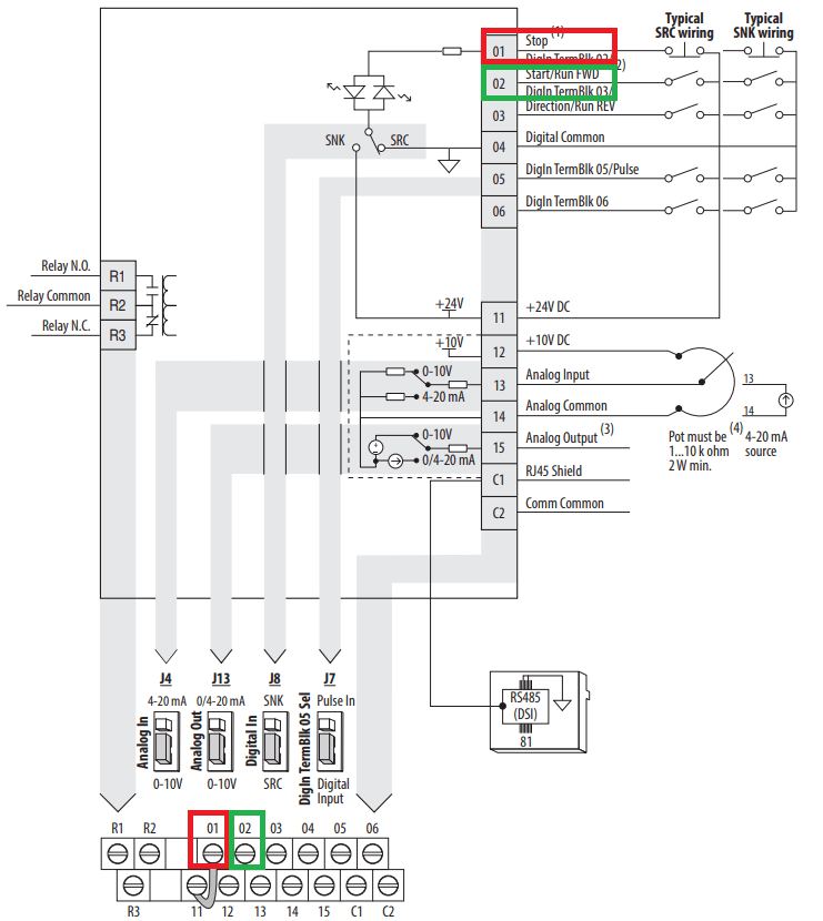
In terms of wiring, the simplest method of controlling the drive without a plc is through the use of a start and stop push buttons. In the reference manual and shown below is a wiring diagram and. Table 1.l 753 main control board details no. Table 52 micrologix wiring diagrams, discrete input and output voltage ranges. Powerflex 753 fault codes version 001 01 may 2018 powerflex 753 fault codes if a fault has occurred, and you are at the telemetry user interface:
 Source: wiringschemas.blogspot.com
On powerflex 753 wiring diagram. Drive modernization part v powerflex 700 to 750 horizon solutions allen bradley vfd instrumentationtools vi 40 525 setup programming parameters wiring diagram rslogix studio 5000 ethernet ip address start stop 753 main control board i o examples tb1 rockwell. The purpose of this manual is to provide you with the basic information. Each enclosure type lends itself to a particular type of protection and environment. Description dpi port 1 (him cradle) connection.
 Source: wiringdiagram.2bitboer.com
Powerflex 753 fault codes version 001 01 may 2018 powerflex 753 fault codes if a fault has occurred, and you are at the telemetry user interface: The examples and diagrams in this manual are included solely for illustrative. Note the fault code in the telemetry user inteface. Drive modernization part v powerflex 700 to 750 horizon solutions allen bradley vfd instrumentationtools vi 40 525 setup programming parameters wiring diagram rslogix studio 5000 ethernet ip address start stop 753 main control board i o examples tb1 rockwell. For a better look, you may open a few examples below.
 Source: wiringdiagram.2bitboer.com
On powerflex 753 wiring diagram. Allen bradley vfd 753 control circuit wiring diagram line wiring diagram. This chapter provides operation and stop category example wiring diagrams. Powerflex 753 fault codes version 001 01 may 2018 powerflex 753 fault codes if a fault has occurred, and you are at the telemetry user interface: Each enclosure type lends itself to a particular type of protection and environment.
 Source: wiringdiagram.2bitboer.com
Wall mount frames 1.3 power terminal block and termination point locations wall mount frame 1 (3) (2) l1 l2 r s wall mount frame 3 (3) (2) no. Powerflex 753 fault codes version 001 01 may 2018 powerflex 753 fault codes if a fault has occurred, and you are at the telemetry user interface: Turn all vfd’s off via the telemetry user interface. Table 52 micrologix wiring diagrams, discrete input and output voltage ranges. Wall mount frames 1.3 power terminal block and termination point locations wall mount frame 1 (3) (2) l1 l2 r s wall mount frame 3 (3) (2) no.
 Source: wiringdiagram.2bitboer.com
The purpose of this manual is to provide you with the basic information. Allen bradley vfd 753 control circuit wiring diagram line wiring diagram. Note the fault code in the telemetry user inteface. Allen bradley vfd wiring diagram full powerflex 755. Table 1.l 753 main control board details no.
 Source: wiringdiagram.2bitboer.com
Table 1.l 753 main control board details no. Powerflex 753 main control board. In the reference manual and shown below is a wiring diagram and. This chapter provides operation and stop category example wiring diagrams. In terms of wiring, the simplest method of controlling the drive without a plc is through the use of a start and stop push buttons.
 Source: wiringdiagram.2bitboer.com
There is an enable input on the main board. Power supply for internal cooling fan (frames 2 & 3). Allen bradley low voltage ac drives powerflex 753 architecture manufacturer from gurgaon. On intex pure spa control base wiring diagram powerflex 753 wiring diagram; The examples and diagrams in this manual are included.
This site is an open community for users to submit their favorite wallpapers on the internet, all images or pictures in this website are for personal wallpaper use only, it is stricly prohibited to use this wallpaper for commercial purposes, if you are the author and find this image is shared without your permission, please kindly raise a DMCA report to Us.
If you find this site beneficial, please support us by sharing this posts to your own social media accounts like Facebook, Instagram and so on or you can also save this blog page with the title powerflex 753 wiring diagrams by using Ctrl + D for devices a laptop with a Windows operating system or Command + D for laptops with an Apple operating system. If you use a smartphone, you can also use the drawer menu of the browser you are using. Whether it’s a Windows, Mac, iOS or Android operating system, you will still be able to bookmark this website.
Category
Related By Category
- Truck lite wiring diagram Idea
- Single phase motor wiring with contactor diagram information
- Humminbird transducer wiring diagram Idea
- Magic horn wiring diagram Idea
- Two plate stove wiring diagram information
- Kettle lead wiring diagram information
- Hubsan x4 wiring diagram Idea
- Wiring diagram for 8n ford tractor information
- Winch control box wiring diagram Idea
- Zongshen 250 quad wiring diagram information