Power inverter remote switch wiring diagram information
Home » Trend » Power inverter remote switch wiring diagram information
Your Power inverter remote switch wiring diagram images are ready in this website. Power inverter remote switch wiring diagram are a topic that is being searched for and liked by netizens today. You can Download the Power inverter remote switch wiring diagram files here. Download all royalty-free photos and vectors.
If you’re searching for power inverter remote switch wiring diagram images information connected with to the power inverter remote switch wiring diagram keyword, you have visit the ideal site. Our site frequently provides you with hints for viewing the highest quality video and image content, please kindly surf and locate more informative video content and graphics that match your interests.
Power Inverter Remote Switch Wiring Diagram. If not, the arrangement won’t work as it ought to be. En 5663 solar wiring diagram pdf inverter home how an functions to works working of connection mains 100 watt circuit 500w 12v 220v batteries and inverters yourhome ac dc full panel. There are four wires going to the remote switch in an rj11 wire. Remote switch is sold separately (pn:
Wiring Diagram Ups schematic and wiring diagram From schematicandwiringdiagram.blogspot.com
100 watt inverter circuit diagram make your own sine wave full. The inverter splits the current into two. The purpose of a dcac power inverter is typically to take dc power supplied by a battery such as a 12 volt car battery and transform it into a 120 volt ac power source operating at 60 hz emulating the power available at an ordinary household electrical outlet. However, if the remote switch is on but the battery voltage drops, the relay will open and cut off the inverter, despite the remote switch still being on. Please careful with this circuit. Repair inverters 100 watt inverter circuit diagram figure 4 c lr internal wiring how an works working of simple 100w solar power uninterruptible supply build 200w digital alternator load schematic note pwm based on sg3524 with feedback control low square wave ic 555 diy board for the lg ltnc11121v designing.
Remote switches for power inverters can turn your inverter off or on if if is mouted in a hard to reach area.
What i don�t know is which of the four conductors in the renogy switch wire is the hot leg of the switch. A fuse box is installed on the positive (red) wire. You’ll be capable to know precisely if the projects ought to be accomplished, that makes it much easier for you to effectively manage your time and efforts. Each part should be set and linked to other parts in particular manner. It is a form of photoelectric cell defined as a device whose electrical characteristics such as current voltage or resistance vary when exposed to light. If not, the arrangement won’t work as it ought to be.
 Source: facybulka.me
If we connect high capacity and a greater number of batteries to the battery bank, then the time for which we can take power from the batteries is increased. 12v 220v pure sine wave power inverter schematic 250 watt homemade circuit projects troubleshooting diagram easyeda simple sinewave circuits generator 800va s reference design rev a make this 1kva 1000 watts 3000w lz2gl digital 1000w dc ac resources switching transformerless 230v 150w modified your own full explanation scientific 800w 300 pwm. You’ll be capable to know precisely if the projects ought to be accomplished, that makes it much easier for you to effectively manage your time and efforts. En 5663 solar wiring diagram pdf inverter home how an functions to works working of connection mains 100 watt circuit 500w 12v 220v batteries and inverters yourhome ac dc full panel. The actual function of the
![[DIAGRAM] Power Inverter Remote Switch Wiring Diagram [DIAGRAM] Power Inverter Remote Switch Wiring Diagram](http://2.bp.blogspot.com/-BMQUpmK4jq8/UuvnkiORHDI/AAAAAAAAArQ/CdCMMb5CNI4/s1600/pinouts.jpg) Source: printer.buffalomountainkombucha.com
Source: printer.buffalomountainkombucha.com
Typical wiring diagram emergency lighting mini central inverter system black white blue white brown black switched command signal violet earth ground green input wiring line switched output neutral normally on normally off output wiring neutral light fixtures led hid incandescent or fluorescent cap off unused wires diagram 1. Remote switch is sold separately (pn: Use 24v dc supply for operation and connect 24v 5a or more than 5a transformer. Each part should be set and linked to other parts in particular manner. If we connect high capacity and a greater number of batteries to the battery bank, then the time for which we can take power from the batteries is increased.

You are using this video at your own. Each part should be set and linked to other parts in particular manner. Remote switch is sold separately (pn: Relay switching the power wont work because the inverter always starts off when powered. This is based on the mosfet3205.
 Source: rvseniormoments.com
Mount this remote to your dash, control panel, or access panel for quick and easy control of your aims power inverter. Power inverter remote switch wiring diagram. Repair inverters 100 watt inverter circuit diagram figure 4 c lr internal wiring how an works working of simple 100w solar power uninterruptible supply build 200w digital alternator load schematic note pwm based on sg3524 with feedback control low square wave ic 555 diy board for the lg ltnc11121v designing. If the inverter switch is on, the power inverter immediately (within 30 ms) supplies ac power to the ac output receptacle. A fuse box is installed on the positive (red) wire.
 Source: motherearthnews.com
The remote terminal is used to set up a remote on/off switch on xp series inverters and the rsw1 or rsw2 for mx series inverters. If not, the arrangement won’t work as it ought to be. Each part should be set and linked to other parts in particular manner. If the inverter switch is on, the power inverter immediately (within 30 ms) supplies ac power to the ac output receptacle. What is the simplest way to get it to control the inverter on/off, and keep an override switch?
Source: vminnovations.com
Mount this remote to your dash, control panel, or access panel for quick and easy control of your aims power inverter. You’ll be capable to know precisely if the projects ought to be accomplished, that makes it much easier for you to effectively manage your time and efforts. Includes a 30 foot cord. The inverter is a device that we will have directly connected to our secondary battery (you can consult our electrical diagrams) and that will basically allow us to convert the electricity provided by our 12v battery to 220v, so we can connect our most common consumables, such as the laptop, through a normal plug,. Power inverter remote switch wiring diagram.
 Source: wiringdiagramimages.wordpress.com
Power inverter remote switch wiring diagram. What i don�t know is which of the four conductors in the renogy switch wire is the hot leg of the switch. Power inverter remote switch wiring diagram. For the inverter, i also want simplicity. A fuse box is installed on the positive (red) wire.
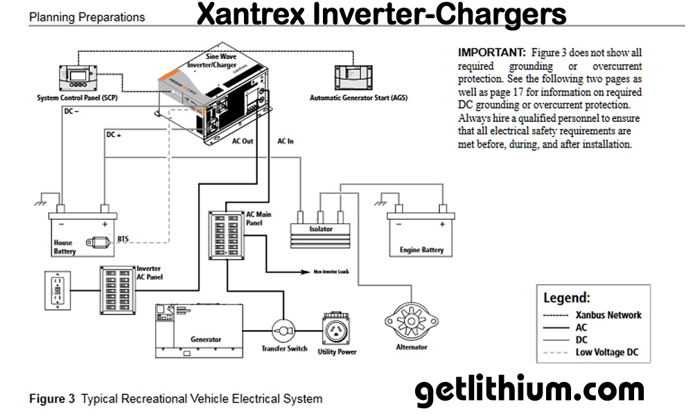
 Source: getlithium.com
In addition to converting dc to ac, the renogy 2000w pure sine wave inverter charger can charge and maintain a battery bank when connected to shore power. Low power square wave inverter circuit using cd4047. The remote switch is parallel to the on/off switch on the front of the inverter, so the front on/off switch must be in the ‘off’ position. This remote also now features a dip switch allowing you to turn on or off the led indicator light. You’ll be capable to know precisely if the projects ought to be accomplished, that makes it much easier for you to effectively manage your time and efforts.
Source: toyota-4runner.org
In the above diagram, three batteries are connected in parallel to each other and power up the inverter’s dc terminals. Also make available a 175 amp plug. In the above diagram, three batteries are connected in parallel to each other and power up the inverter’s dc terminals. Pdf design of single phase to three static power converter. Solar power inverter circuit diagram pdf.
 Source: roadtreklife.blogspot.com
12v 220v pure sine wave power inverter schematic 250 watt homemade circuit projects troubleshooting diagram easyeda simple sinewave circuits generator 800va s reference design rev a make this 1kva 1000 watts 3000w lz2gl digital 1000w dc ac resources switching transformerless 230v 150w modified your own full explanation scientific 800w 300 pwm. This is based on the mosfet3205. Low power square wave inverter circuit using cd4047. It is a form of photoelectric cell defined as a device whose electrical characteristics such as current voltage or resistance vary when exposed to light. There are four wires going to the remote switch in an rj11 wire.
Source: schematicandwiringdiagram.blogspot.com
There are four wires going to the remote switch in an rj11 wire. In the above diagram, three batteries are connected in parallel to each other and power up the inverter’s dc terminals. This remote also now features a dip switch allowing you to turn on or off the led indicator light. Cobra cpi a20 power inverter remote control wall plate switch 20 foot wiring high power capacity models compatible. They are usually connected with a standard telephone cable.
 Source: wiringdiagramall.blogspot.com
Rather than soldering wires across power switch, i want to use it�s build in rj11 port. Power inverter remote switch wiring diagram. Remote switches for power inverters can turn your inverter off or on if if is mouted in a hard to reach area. I see no reason to have anything displayed or controlled (except remote on/off via the bms). Typical wiring diagram emergency lighting mini central inverter system (black) (white) (blue) (white) (brown) (black) switched command signal (violet) earth ground (green) input wiring line switched output neutral normally on normally off output wiring neutral light fixtures (led, hid, incandescent or fluorescent) *cap off unused wires diagram #1
Source: fjelloghjem.blogspot.com
Please careful with this circuit. This is the circuit diagram of 2000w high power inverter circuit. The remote terminal is used to set up a remote on/off switch on xp series inverters and the rsw1 or rsw2 for mx series inverters. The inverter is a device that we will have directly connected to our secondary battery (you can consult our electrical diagrams) and that will basically allow us to convert the electricity provided by our 12v battery to 220v, so we can connect our most common consumables, such as the laptop, through a normal plug,. I even took it apart and couldn�t figure out.
![[DIAGRAM] Power Inverter Remote Switch Wiring Diagram [DIAGRAM] Power Inverter Remote Switch Wiring Diagram](https://i1.wp.com/tops-stars.com/wp-content/uploads/2017/09/fujitsu-split-system-wiring-diagram-fujitsu-mini-split-wiring-inside-fujitsu-wiring-diagram.jpg?resize%5Cu003d665%2C474%5Cu0026ssl%5Cu003d1) Source: printer.buffalomountainkombucha.com
Source: printer.buffalomountainkombucha.com
If not, the arrangement won’t work as it ought to be. It is a form of photoelectric cell defined as a device whose electrical characteristics such as current voltage or resistance vary when exposed to light. For the inverter, i also want simplicity. This remote is compatible with the following newly purchased models: Use 24v dc supply for operation and connect 24v 5a or more than 5a transformer.
 Source: projectboatzen.com
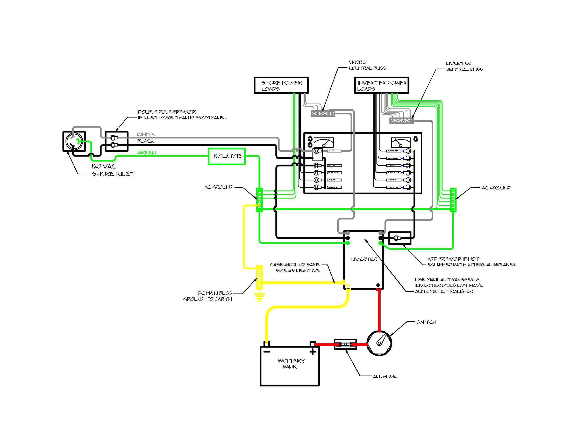
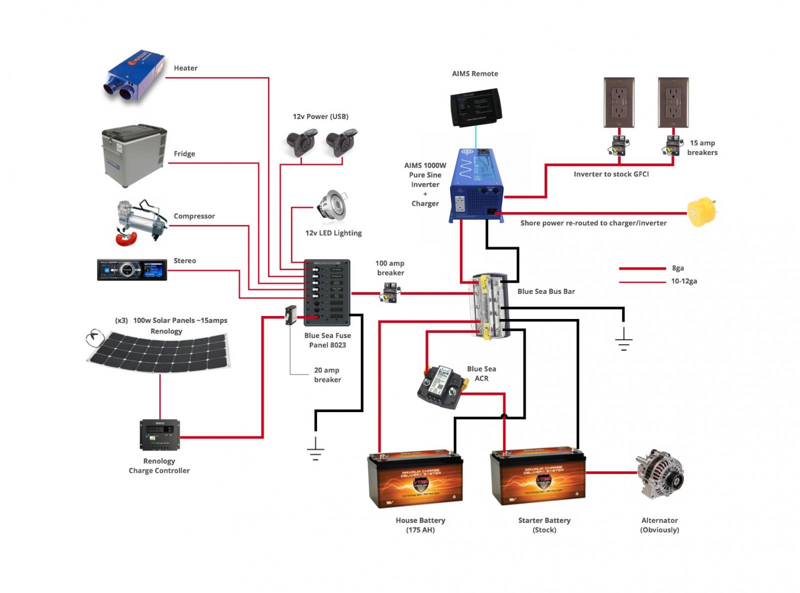
Below you will find the most standard rv inverter wiring diagram. The remote switch is parallel to the on/off switch on the front of the inverter, so the front on/off switch must be in the ‘off’ position. You’ll be capable to know precisely if the projects ought to be accomplished, that makes it much easier for you to effectively manage your time and efforts. When magnet movement to hall sensor effect to rf transmitter turn on has signal to rf receiver. This is the circuit diagram of 2000w high power inverter circuit.
 Source: roadtreklife.blogspot.com
If not, the arrangement won’t work as it ought to be. The purpose of a dcac power inverter is typically to take dc power supplied by a battery such as a 12 volt car battery and transform it into a 120 volt ac power source operating at 60 hz emulating the power available at an ordinary household electrical outlet. The latter, being normally closed, leaves control of the inverter to the remote switch. The inverter splits the current into two. Rv inverter wiring diagram 3 what is an rv inverter?
 Source: schematron.org
Rather than soldering wires across power switch, i want to use it�s build in rj11 port. The remote switch is parallel to the on/off switch on the front of the inverter, so the front on/off switch must be in the ‘off’ position. Remote switch is sold separately (pn: Rv inverter install the remote switch. Use 24v dc supply for operation and connect 24v 5a or more than 5a transformer.
 Source: thesamba.com
If the inverter switch is on, the power inverter immediately (within 30 ms) supplies ac power to the ac output receptacle. Includes a 30 foot cord. Each part should be set and linked to other parts in particular manner. A fuse box is installed on the positive (red) wire. Below you will find the most standard rv inverter wiring diagram.
This site is an open community for users to do sharing their favorite wallpapers on the internet, all images or pictures in this website are for personal wallpaper use only, it is stricly prohibited to use this wallpaper for commercial purposes, if you are the author and find this image is shared without your permission, please kindly raise a DMCA report to Us.
If you find this site good, please support us by sharing this posts to your favorite social media accounts like Facebook, Instagram and so on or you can also save this blog page with the title power inverter remote switch wiring diagram by using Ctrl + D for devices a laptop with a Windows operating system or Command + D for laptops with an Apple operating system. If you use a smartphone, you can also use the drawer menu of the browser you are using. Whether it’s a Windows, Mac, iOS or Android operating system, you will still be able to bookmark this website.
Category
Related By Category
- Predator 670 engine wiring diagram Idea
- Frsky x8r wiring diagram information
- Pioneer ts wx130da wiring diagram Idea
- Johnson 50 hp wiring diagram Idea
- Kohler voltage regulator wiring diagram Idea
- Johnson 50 hp outboard wiring diagram information
- Kti hydraulic remote wiring diagram Idea
- Pyle plpw12d wiring diagram information
- Tx9600ts wiring diagram information
- Lifan 50cc wiring diagram information