Power cap wiring diagram Idea
Home » Trend » Power cap wiring diagram Idea
Your Power cap wiring diagram images are ready in this website. Power cap wiring diagram are a topic that is being searched for and liked by netizens now. You can Download the Power cap wiring diagram files here. Get all free images.
If you’re looking for power cap wiring diagram images information connected with to the power cap wiring diagram keyword, you have pay a visit to the ideal blog. Our website always gives you hints for refferencing the highest quality video and picture content, please kindly search and find more enlightening video content and images that match your interests.
Power Cap Wiring Diagram. 2) mock up your wire lengths for your planned esc placement. Ac power cord wiring diagram. The circuit diagram of single phase. The downside of this type of connection is you don�t know if the power capacitor fails since the.
 Ballastco Lighting Capacitors Ballastco From ballastco.net
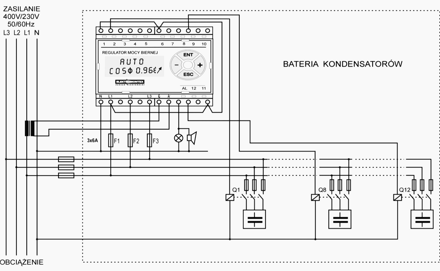
Connection diagrams for factor correction capacitors kvar guide. What purpose do capacitors serve in a power supply? Power factor correction capacitor wiring diagram what is power factor correction definition methods circuit globe. The downside of this type of connection is you don�t know if the power capacitor fails since the. Speakers wiring to capacitor car diagrams explained table fan diagram with pdf start single phase motor table fan capacitor connection table ceiling fan speed. It is recommended to solder the power cap and all leads to the esc before mounting to the chassis.
Multi speed 3 phase motor 3 speeds 1 direction power control diagrams one line diagram of simple contactor circuit.
It is intended to help all the typical user in building a correct program. Hello, i�m planning to make my own custom sleeved psu cables for corsair pin connection on psu side,using additional capacitors for extra c. These instructions will probably be easy to comprehend and implement. Truck cap / tonneau cover leer triple 12v power outlet including wiring harness see more like this. The circuit diagram of single phase. Step by tutorial for building capacitor bank and reactive power compensation panel eep working symbol calculation its applications wiring modes alpes technologies electrical4u.
 Source: schematron.org
Actually, we have been realized that are truck cap parts diagram is being just about the most popular topic at this time. Baldor single phase 230v motor wiring diagram. It usually shows how to wire the motor for common configurations such as 110 to 125 volts or 220 to 250 volts and occasionally 208 volts. Another split phase capacitor run type of electric motor utilizes a capacitor transformer unit and is of the split phase squirrel cage type with the main and auxiliary winding’s physically displaced in the stator. The different types of ac power connectors in north america.
 Source: pinterest.com
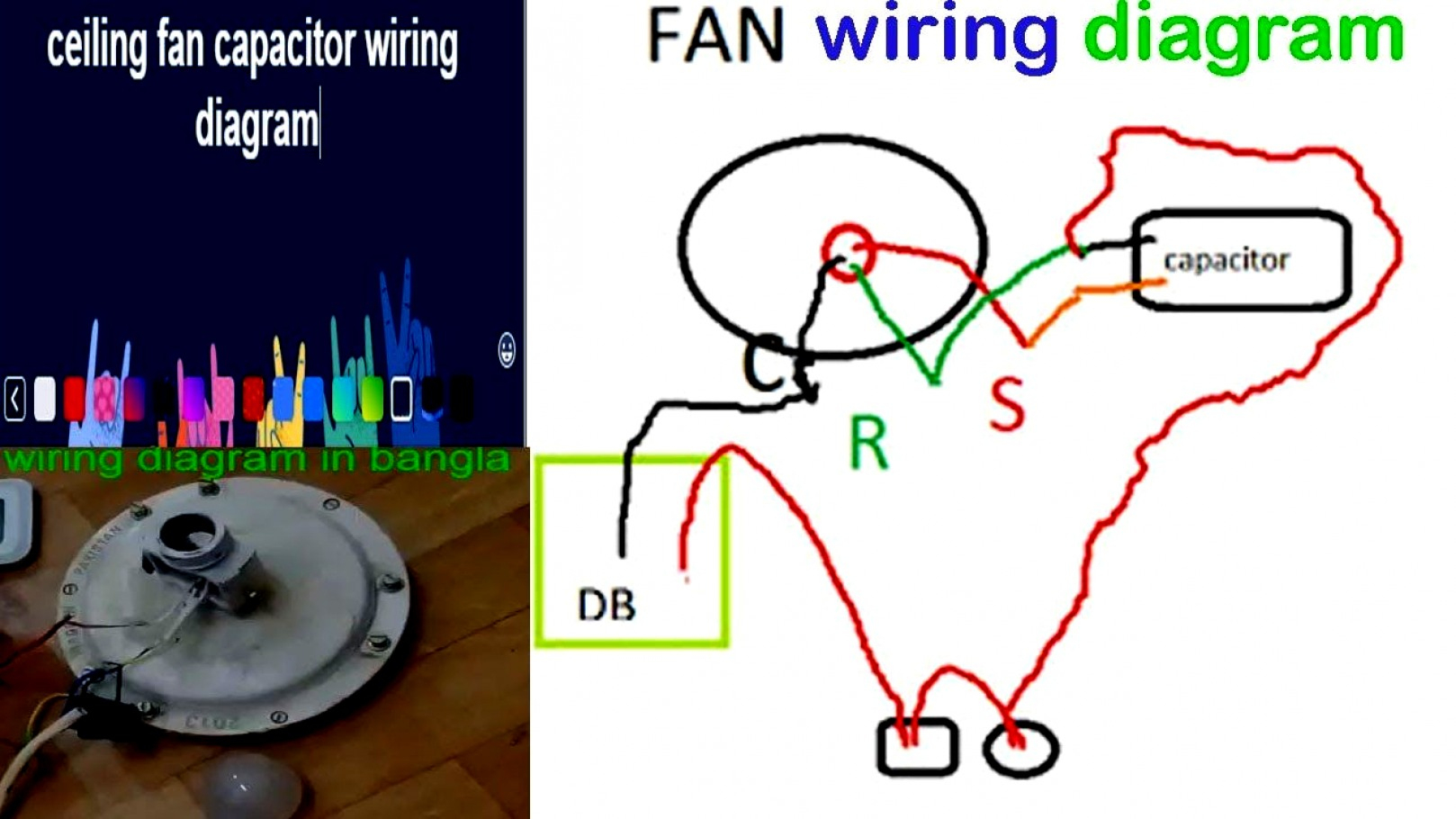
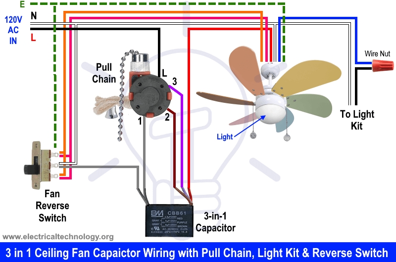
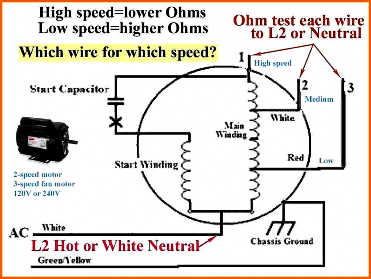
The downside of this type of connection is you don�t know if the power capacitor fails since the. Capacitor motor single phase wiring diagrams always use wiring diagram supplied on motor nameplate. Ceiling fan capacitor connection diagram 3 wire ceiling fan capacitor diagram 5 wire ceiling fan capacitor diagram and installation role of capacitor in fan and single phase motor so in above diagram the speed switch contacts on l 3 and 2 5 uf and. Actually, we have been realized that are truck cap parts diagram is being just about the most popular topic at this time. Truck cap / tonneau cover leer triple 12v power outlet including wiring harness see more like this.
 Source: electrical-engineering-portal.com
The power capacitor acts like a small battery (power storage) so it is connected as shown in the diagram. + items in search results. Another split phase capacitor run type of electric motor utilizes a capacitor transformer unit and is of the split phase squirrel cage type with the main and auxiliary winding’s physically displaced in the stator. As stated earlier, the lines at a are truck cap wiring diagram signifies wires. Factor correction capacitors kvar the circuit diagram of single phase which type power installing reactive compensation panel circuitry for improvement practical what is pfc three 200 415 v apfc.
 Source: diy.stackexchange.com
A wiring diagram is a streamlined conventional photographic representation of an electrical circuit. Power factor correction capacitor wiring diagram. It usually shows how to wire the motor for common configurations such as 110 to 125 volts or 220 to 250 volts and occasionally 208 volts. 3) choose a wiring method for the motor and battery leads. The downside of this type of connection is you don�t know if the power capacitor fails since the.
 Source: 2020cadillac.com
Power acoustik capacitor wiring diagram pdf , related gallery: Ac power cord wiring diagram. This article describes how to install a 30 amp shore power system on a small boat. Similar to grating to remove, replace or repair the wiring in an automobile, having an accurate and detailed power factor. Car power window wiring diagram.
 Source: diagramweb.net
The iec 60320 c13 14. So that we tried to identify some terrific are truck cap parts. The simplest approach to read a home wiring diagram is to begin at the source or the major power supply. Voltage reversal is the simple process of switching polarity to change the direction of an electric motor. Shore power plug wiring diagram.
 Source: alquilercastilloshinchables.info
Rmi wiring pc power supply discussion. Factory power wiring factory control wiring field control wiring field power wiring component connection field splice junction cont cap *ch *chs comp *ctd *dts *hps ifr *lls *lps ofm *sc *sr *st contactor capacitor (dual run) crankcase heater crankcase heater switch. The two motor window circuit in the diagram above uses voltage reversal rest at ground. The iec 60320 c13 14. Generally the circuit breaker for the rv shore power is located at the pedestal you plug into.
 Source: wiringall.com
In this mode loads connected to the ac output. A wiring diagram is a streamlined conventional photographic representation of an electrical circuit. Insulate connections and unused harnesses if a connection or unused harness touches your body, a fire, electric It reveals the elements of the circuit as simplified shapes and the power and signal connections between the tools. So that we tried to identify some terrific are truck cap parts.
 Source: untpikapps.com
The circuit diagram of single phase. What purpose do capacitors serve in a power supply? The simplest approach to read a home wiring diagram is to begin at the source or the major power supply. It usually shows how to wire the motor for common configurations such as 110 to 125 volts or 220 to 250 volts and occasionally 208 volts. Baldor single phase 230v motor wiring diagram.
 Source: pinterest.com
Wiring diagram line we are make source the schematics, wiring diagrams and technical photos. Shore power plug wiring diagram. Hello, i�m planning to make my own custom sleeved psu cables for corsair pin connection on psu side,using additional capacitors for extra c. The shore power cord has a male plug on both ends. Note the reversal of the active and neutral wires depending on whether you are wiring a socket or a plug.
 Source: pinterest.com
Car power window wiring diagram. Actually, we have been realized that are truck cap parts diagram is being just about the most popular topic at this time. A wiring diagram is a streamlined conventional photographic representation of an electrical circuit. Voltage reversal is the simple process of switching polarity to change the direction of an electric motor. Power acoustik capacitor wiring diagram pdf , related gallery:
 Source: annawiringdiagram.com
The two motor window circuit in the diagram above uses voltage reversal rest at ground. This will cause your amplifier�s power supply to be cut off. Direct wiring uses no plugs and provides the best With regard to are truck cap parts diagram, image size 941 x 522 px, and to view image details please click the image. 3) choose a wiring method for the motor and battery leads.

Multi speed 3 phase motor 3 speeds 1 direction power control diagrams one line diagram of simple contactor circuit. Actually, we have been realized that are truck cap parts diagram is being just about the most popular topic at this time. Ac power cord wiring diagram. It contains guidelines and diagrams for different types of wiring strategies as well as other products like lights, windows, and so forth. Another split phase capacitor run type of electric motor utilizes a capacitor transformer unit and is of the split phase squirrel cage type with the main and auxiliary winding’s physically displaced in the stator.
 Source: aedbaeddebbefddk.blogspot.com
Any content, trademark/s, or other material that might be found on the www.smarts4k.com website that is not www.smarts4k.com property remains the copyright of its respective owner/s. See search results that fit your vehicle. At times, the wires will cross. Factor correction capacitors kvar the circuit diagram of single phase which type power installing reactive compensation panel circuitry for improvement practical what is pfc three 200 415 v apfc. Note that the two terminals do not both connect to the +12 volt power wire.
 Source: terrycaliendo.com
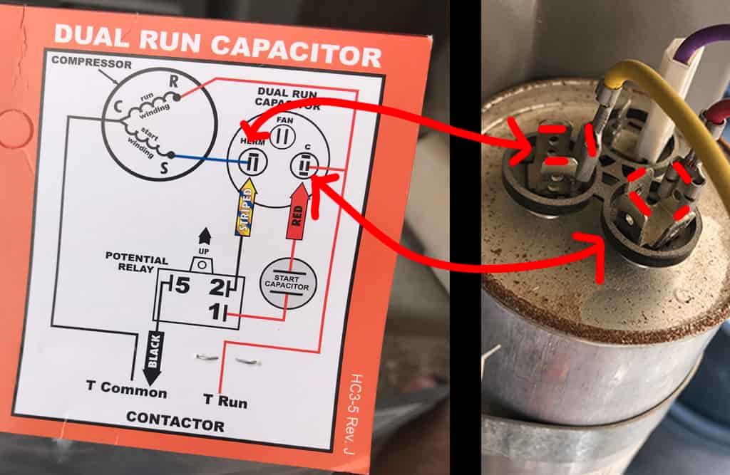
- items in search results. Ystill larger yachts may use a 50 ampere or 100 ampere 125250 volt system fig. Each component ought to be placed and linked to different parts in. Here you go, follow the diagram, it�s the power and the start and run caps: 3) choose a wiring method for the motor and battery leads.
 Source: pinterest.com
However, it doesn’t imply link between the wires. Factory power wiring factory control wiring field control wiring field power wiring component connection field splice junction cont cap *ch *chs comp *ctd *dts *hps ifr *lls *lps ofm *sc *sr *st contactor capacitor (dual run) crankcase heater crankcase heater switch. This will cause your amplifier�s power supply to be cut off. Capacitor motor single phase wiring diagrams always use wiring diagram supplied on motor nameplate. Connection diagrams for factor correction capacitors kvar guide.
 Source: wiringforums.com
Here you go, follow the diagram, it�s the power and the start and run caps: Ac power cord wiring diagram. Power factor correction capacitor wiring diagram. Note the reversal of the active and neutral wires depending on whether you are wiring a socket or a plug. In this mode loads connected to the ac output.
 Source: ballastco.net
Wiring diagram will come with numerous easy to follow wiring diagram directions. Rmi wiring pc power supply discussion. Generally the circuit breaker for the rv shore power is located at the pedestal you plug into. Similar to grating to remove, replace or repair the wiring in an automobile, having an accurate and detailed power factor. Note that the two terminals do not both connect to the +12 volt power wire.
This site is an open community for users to do sharing their favorite wallpapers on the internet, all images or pictures in this website are for personal wallpaper use only, it is stricly prohibited to use this wallpaper for commercial purposes, if you are the author and find this image is shared without your permission, please kindly raise a DMCA report to Us.
If you find this site convienient, please support us by sharing this posts to your own social media accounts like Facebook, Instagram and so on or you can also bookmark this blog page with the title power cap wiring diagram by using Ctrl + D for devices a laptop with a Windows operating system or Command + D for laptops with an Apple operating system. If you use a smartphone, you can also use the drawer menu of the browser you are using. Whether it’s a Windows, Mac, iOS or Android operating system, you will still be able to bookmark this website.
Category
Related By Category
- Predator 670 engine wiring diagram Idea
- Frsky x8r wiring diagram information
- Pioneer ts wx130da wiring diagram Idea
- Johnson 50 hp wiring diagram Idea
- Kohler voltage regulator wiring diagram Idea
- Johnson 50 hp outboard wiring diagram information
- Kti hydraulic remote wiring diagram Idea
- Pyle plpw12d wiring diagram information
- Tx9600ts wiring diagram information
- Lifan 50cc wiring diagram information