Potential relay wiring diagram information
Home » Trend » Potential relay wiring diagram information
Your Potential relay wiring diagram images are available. Potential relay wiring diagram are a topic that is being searched for and liked by netizens now. You can Get the Potential relay wiring diagram files here. Find and Download all royalty-free images.
If you’re looking for potential relay wiring diagram pictures information connected with to the potential relay wiring diagram interest, you have come to the ideal blog. Our site frequently provides you with suggestions for seeking the highest quality video and image content, please kindly surf and find more informative video articles and images that fit your interests.
Potential Relay Wiring Diagram. The back emf is usually a higher voltage than the line voltage and can be in the 400 v area. Potential relay wiring diagram compressor potential relay wiring diagram copeland potential relay wiring diagram mars potential relay wiring diagram every electrical arrangement consists of various distinct components. Their function is to assist in starting the electric motor. If your setup is not working, the coil may not be wired across the correct points.
![[DIAGRAM] Copeland Potential Relay Wiring Diagram Run [DIAGRAM] Copeland Potential Relay Wiring Diagram Run](https://i.pinimg.com/originals/4b/e3/38/4be338bdadd3722e7eae07cebaadb305.jpg) [DIAGRAM] Copeland Potential Relay Wiring Diagram Run From diagramcloud.blogspot.com
[DIAGRAM] Copeland Potential Relay Wiring Diagram Run From diagramcloud.blogspot.com
A circuit is usually composed by several components. The universal potential motor starting relay wiring diagram and cross reference. If your setup is not working, the coil may not be wired across the correct points. The other thing which you will get a circuit diagram would be lines. These relays meet all requirements for original equipment relays. You’ll be capable to learn precisely if the assignments needs to be accomplished, that makes it much simpler to suit your needs to correctly manage your time.
A circuit is usually composed by many components.
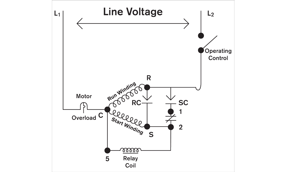
As the engine increases the speed, high voltage of primary windings energizes the relay coil, 2 and 5. It can be used for various switching. If a potential relay with a continuous coil rating that is too low is applied to a compressors starting circuit the relay will fail. • replaces wire by wire virtually any potential relay on the market. The coil is wired between terminals 2 and 5, with the contacts between terminals 1 and 2. You’ll be capable to learn precisely if the assignments needs to be accomplished, that makes it much simpler to suit your needs to correctly manage your time.
 Source: schematron.org
Tim uses the interactive wiring diagrams. If your setup is not working, the coil may not be wired across the correct points. If your setup is not working, the coil may not be wired across the correct points. • 50/60 hz • culus • contact rating 35 amp, 400 vac • operating position tab up • instructions and wiring diagram included in each relay • class “b” insulation c o m p o n e n t s ® marsdelivers.com Mars relays & potential relays for submersible pump applications the mars 550 and 551 relays were specifically developed for submersible pump and other motor starting applications in high moisture environments.
 Source: dentistmitcham.com
Tim uses the interactive wiring diagrams. Headlight relay wiring diagram the above circuit is a way to use existing headlight wiring to control 2 relays that can be placed close to the lights. Assembly consisting of a start and run capacitor and a potential relay will be with the position of the capacitors and relay shown on the wiring diagram.csr motor diagram. A circuit is usually composed by many components. If playback doesn�t begin shortly, try restarting your device.
 Source: annawiringdiagram.com
This is the wiring of the potential relay. For example, it uses a single line to represent three phases (hence the name “single line”). There are two things which are going to be present in almost any potential relay wiring diagram. You’ll be capable to learn precisely if the assignments needs to be accomplished, that makes it much simpler to suit your needs to correctly manage your time. Headlight relay wiring diagram the above circuit is a way to use existing headlight wiring to control 2 relays that can be placed close to the lights.
 Source: hvacrschool.com
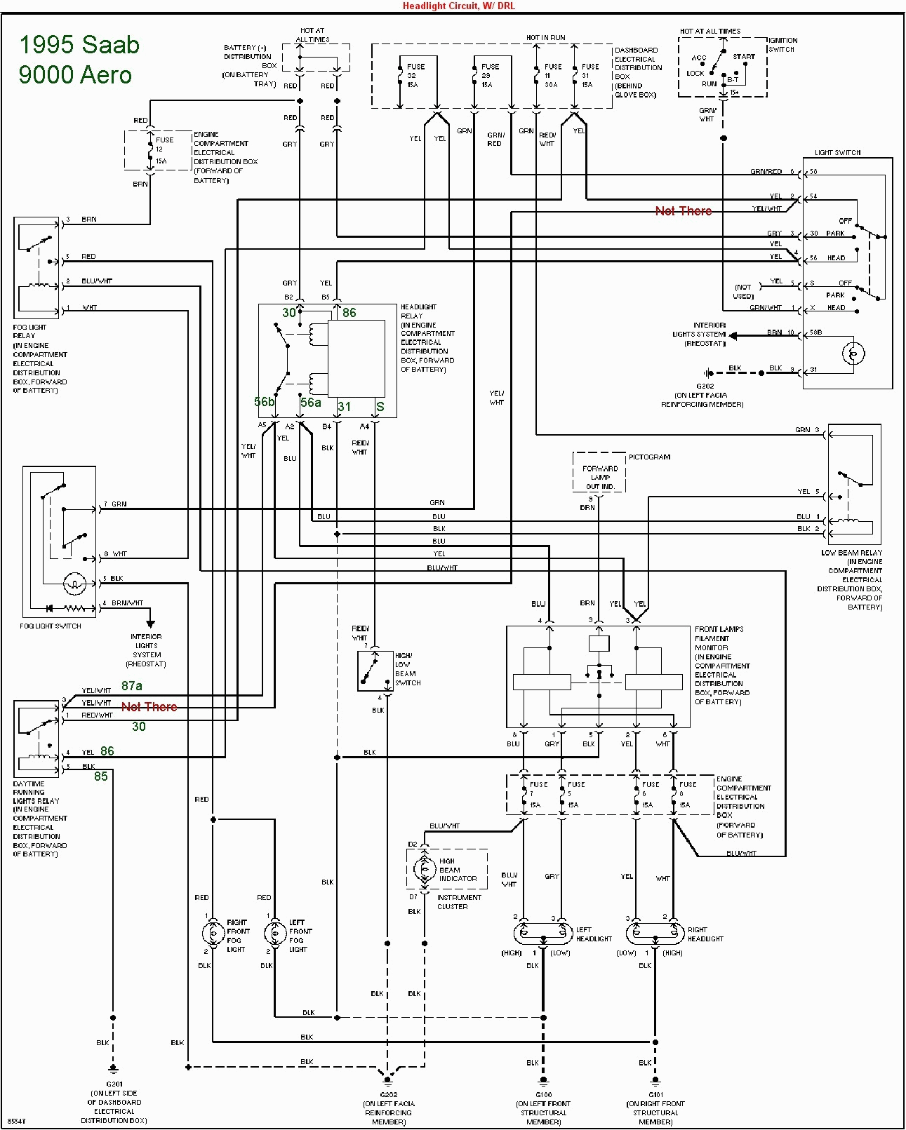
The diagram above is the 5 pin relay wiring diagram. Wiring diagram for potential relay wiring diagram line wiring diagram wiring diagram line we are make source the schematics, wiring diagrams and technical photos Potential relay wiring diagram compressor potential relay wiring diagram copeland potential relay wiring diagram mars potential relay wiring diagram every electrical arrangement consists of various distinct components. Listed underneath is a awesome photo for halogen headlight wiring diagrams. There are two things that will be present in almost any potential relay wiring diagram.
 Source: wholefoodsonabudget.com
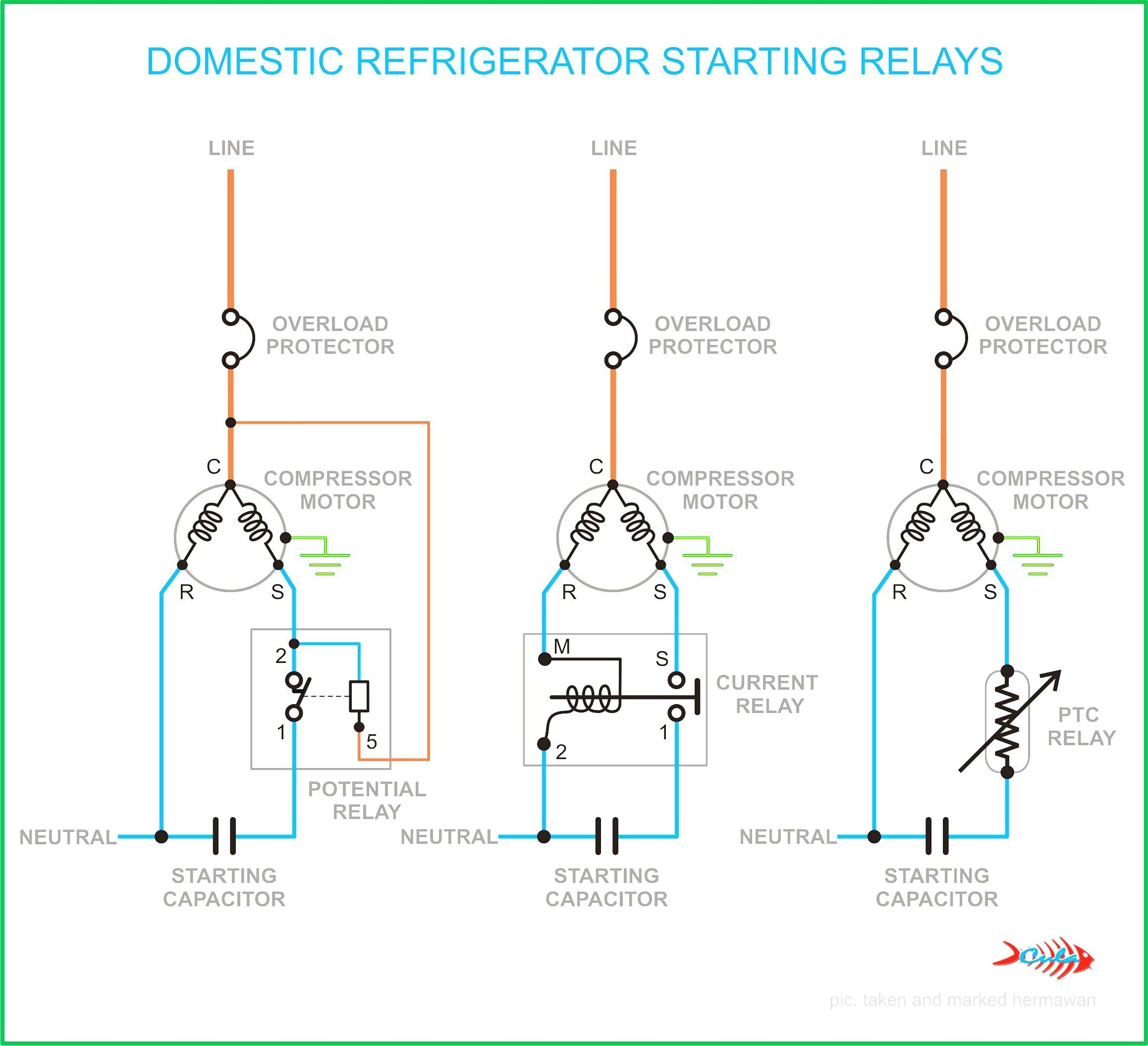
There are different kinds of relays for different purposes. Supco relay wiring diagram wiring diagram is a simplified pleasing pictorial representation of an electrical circuit. Their function is to assist in starting the electric motor. 2 and 5 are the coil, the nc switch is between 1 and 2. Wiring diagram for potential relay wiring diagram line wiring diagram wiring diagram line we are make source the schematics, wiring diagrams and technical photos
 Source: annawiringdiagram.com
The wiring diagram for a potential relay is shown in ill the potential. The back emf is usually a higher voltage than the line voltage and can be in the 400 v area. If your setup is not working, the coil may not be wired across the correct points. The other thing which you will get a circuit diagram would be lines. As the engine increases the speed, high voltage of primary windings energizes the relay coil, 2 and 5.
Source: radiowiring.blogspot.com
As the engine increases the speed, high voltage of primary windings energizes the relay coil, 2 and 5. Assembly consisting of a start and run capacitor and a potential relay will be with the position of the capacitors and relay shown on the wiring diagram.csr motor diagram. Tim uses the interactive wiring diagrams. The coil is wired between terminals 2 and 5, with the contacts between terminals 1 and 2. There are different kinds of relays for different purposes.
 Source: bibliotekakarpacz.pl
There are two things that will be present in almost any potential relay wiring diagram. The diagram above is the 5 pin relay wiring diagram. This video is part of the heating and cooling series of training videos made to accompany. Headlight relay wiring diagram the above circuit is a way to use existing headlight wiring to control 2 relays that can be placed close to the lights. File type pdf compressor potential relay wiring diagram compressor potential relay wiring diagram thank you unconditionally much for downloading compressor potential relay wiring diagram.maybe you have knowledge that, people have see numerous time for their favorite books later than this compressor potential relay wiring diagram, but end occurring in harmful.
 Source: apiccolisogni.blogspot.com
There are two things that will be present in almost any potential relay wiring diagram. You’ll be capable to learn precisely if the assignments needs to be accomplished, that makes it much simpler to suit your needs to correctly manage your time. Mars hvac potential relays mars series relays are manufactured for the hvac industry. • replaces wire by wire virtually any potential relay on the market. Relay coil is connected through the starting winding.
![[DIAGRAM] Copeland Potential Relay Wiring Diagram Run [DIAGRAM] Copeland Potential Relay Wiring Diagram Run](https://i.pinimg.com/originals/4b/e3/38/4be338bdadd3722e7eae07cebaadb305.jpg) Source: diagramcloud.blogspot.com
Source: diagramcloud.blogspot.com
As the engine increases the speed, high voltage of primary windings energizes the relay coil, 2 and 5. Listed underneath is a awesome photo for halogen headlight wiring diagrams. It opens normally closed contacts, 1 and 2. Assembly consisting of a start and run capacitor and a potential relay will be with the position of the capacitors and relay shown on the wiring diagram.csr motor diagram. The first element is emblem that indicate electric element from the circuit.
 Source: wiringdiagram.2bitboer.com
The hardship in reality is that all car is different. It can be used for various switching. • replaces wire by wire virtually any potential relay on the market. Relay can be the best option to control electrical devices automatically. 2 and 5 are the coil, the nc switch is between 1 and 2.
 Source: annawiringdiagram.com
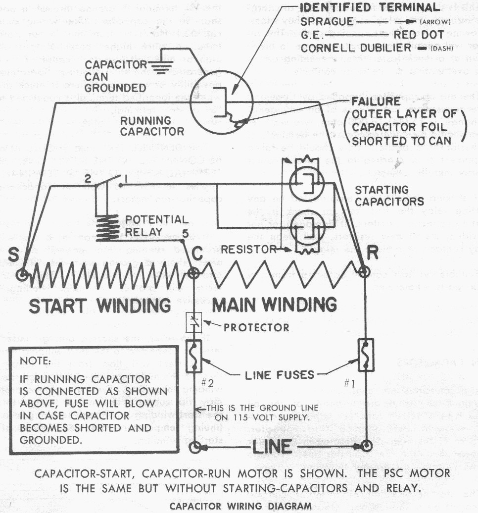
Videos you watch may be added to the tv�s watch history and influence tv recommendations. Terminals 4 and 6 are used for capacitors and/or condenser fan connections and have no electrical significance to the starting relay itself, as shown in figure 1. Subsequent to a pain to remove, replace or repair the wiring in an automobile, having an accurate and detailed. Videos you watch may be added to the tv�s watch history and influence tv recommendations. As the engine increases the speed, high voltage of primary windings energizes the relay coil, 2 and 5.
Source: apiccolisogni.blogspot.com
Each part should be set and connected with different parts in particular way. Starting winding, therefore, threw the chain. The coil is wired between terminals 2 and 5, with the contacts between terminals 1 and 2. Amazon try prime all includes wiring diagram and instructions on relay. This video is part of the heating and cooling series of training videos made to accompany.
 Source: annawiringdiagram.com
This is the wiring of the potential relay. Headlight relay wiring diagram the above circuit is a way to use existing headlight wiring to control 2 relays that can be placed close to the lights. If your setup is not working, the coil may not be wired across the correct points. 2 and 5 are the coil, the nc switch is between 1 and 2. If playback doesn�t begin shortly, try restarting your device.
 Source: meryuskasthings.blogspot.com
These relays meet all requirements for original equipment relays. Their function is to assist in starting the electric motor. The first element is symbol that indicate electric element in the circuit. 5 pin is compromised of 3 main. If a potential relay with a continuous coil rating that is too low is applied to a compressors starting circuit the relay will fail.
 Source: youtube.com
The first element is emblem that indicate electric element from the circuit. $ $ 31 09 prime. 2 and 5 are the coil, the nc switch is between 1 and 2. Assembly consisting of a start and run capacitor and a potential relay will be with the position of the capacitors and relay shown on the wiring diagram.csr motor diagram. There are two things which are going to be present in almost any potential relay wiring diagram.
 Source: practicalmachinist.com
The hardship in reality is that all car is different. Components of potential relay wiring diagram and a few tips. There are different kinds of relays for different purposes. The diagram above is the 5 pin relay wiring diagram. As the engine increases the speed, high voltage of primary windings energizes the relay coil, 2 and 5.
 Source: worldvisionsummerfest.com
Videos you watch may be added to the tv�s watch history and influence tv recommendations. 2 and 5 are the coil, the nc switch is between 1 and 2. Free shipping on eligible orders. Mars relays & potential relays for submersible pump applications the mars 550 and 551 relays were specifically developed for submersible pump and other motor starting applications in high moisture environments. • replaces wire by wire virtually any potential relay on the market.
This site is an open community for users to share their favorite wallpapers on the internet, all images or pictures in this website are for personal wallpaper use only, it is stricly prohibited to use this wallpaper for commercial purposes, if you are the author and find this image is shared without your permission, please kindly raise a DMCA report to Us.
If you find this site value, please support us by sharing this posts to your own social media accounts like Facebook, Instagram and so on or you can also bookmark this blog page with the title potential relay wiring diagram by using Ctrl + D for devices a laptop with a Windows operating system or Command + D for laptops with an Apple operating system. If you use a smartphone, you can also use the drawer menu of the browser you are using. Whether it’s a Windows, Mac, iOS or Android operating system, you will still be able to bookmark this website.
Category
Related By Category
- Predator 670 engine wiring diagram Idea
- Frsky x8r wiring diagram information
- Pioneer ts wx130da wiring diagram Idea
- Johnson 50 hp wiring diagram Idea
- Kohler voltage regulator wiring diagram Idea
- Johnson 50 hp outboard wiring diagram information
- Kti hydraulic remote wiring diagram Idea
- Pyle plpw12d wiring diagram information
- Tx9600ts wiring diagram information
- Lifan 50cc wiring diagram information