Pool pump timer wiring diagram Idea
Home » Trend » Pool pump timer wiring diagram Idea
Your Pool pump timer wiring diagram images are available. Pool pump timer wiring diagram are a topic that is being searched for and liked by netizens today. You can Download the Pool pump timer wiring diagram files here. Download all free photos and vectors.
If you’re searching for pool pump timer wiring diagram images information connected with to the pool pump timer wiring diagram keyword, you have pay a visit to the right site. Our website always gives you suggestions for downloading the highest quality video and image content, please kindly surf and find more enlightening video content and graphics that match your interests.
Pool Pump Timer Wiring Diagram. I am replacing my 1 speed pump which is wired with 110v. Intermatic pool pump timer wiring diagram,. How to wire intermatic t104 and t103 and t101 timers throughout pool pump timer wiring diagram image size 586 x 350 px. Running pool equipment 24 hours is usually unnecessary and.
 Intermatic 240v Timer Wiring Diagram Free Wiring Diagram From ricardolevinsmorales.com
Universal mtd8 programmable din rail digital timer (major tech brand) Click on the image to enlarge and then save it to your computer by right clicking on the image. Shop swimming pool pump timer wiring diagram, choose swimming pool pump timer wiring diagram from top brands, swimming pool pump timer wiring diagram for sale from ebay! A wiring diagram usually gives recommendation practically the relative outlook and union of devices and. Intermatic pool timer wiring diagram just what s wiring diagram. Not merely will it help you achieve your required outcomes more quickly, but also make the entire procedure simpler for everybody.
Including diagrams for t, t, t timers pool timers have same wiring as t series, except with fireman�s switch.
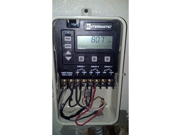
How to wire intermatic t and t and t timers. Select feature enables timers to be continuously in on/off/auto mode. Clock motor voltage and cycle must be as specified. Intermatic pool timer wiring diagram just whats wiring diagram. The wiring is quite simple. In the pic you see there, the two black cables on the right opening are coming from the breaker.
 Source: wholefoodsonabudget.com
Not merely will it help you achieve your required outcomes more quickly, but also make the entire procedure simpler for everybody. The timer is an intermatic timer 220v. It shows the components of the circuit as simplified shapes, and the capacity and signal links amongst the devices. Otherwise, the arrangement will not function as it ought to be. The speaker wiring diagram and connection guide the basics you need to know speaker wire types.
 Source: ricardolevinsmorales.com
Wire diagram for sand filter pump trouble free pool wiring diynot forums timer questions motor overheats doityourself com community removing a simple way to turn on off using st 17 by paul haskins projects stories smartthings stopped pumping ecopump brochure and spec s question diy home improvement forum help i have hayward 1 2 hp model. Bestway steel pro 15 foot x 48quot; These instructions will likely be easy to comprehend and implement. Sometimes the wires will cross. Identify and locate the pool pump timer s wire terminals using the timer s schematic as a guide.

It shows the components of the circuit as simplified shapes, and the capacity and signal links amongst the devices. How to wire intermatic t and t and t timers. A wiring diagram is a kind of schematic which uses abstract pictorial symbols to show all the affiliations of components in a system. I currently have a manual t101r intermatic time clock for my pool pump. Swimming pool electrical wiring diagram swimming pool electrical wiring diagram luxury fine pool pump timer wiring diagram electrical circuit file type.
 Source: skippingtheinbetween.blogspot.com
The timer is an intermatic timer 220v. To order replacement, indicate part no. The orange tube on the bottom opening is coming from the pool motor. Tm613 3 phase line 380v 415v tm613 3 phase line 380v 415v swimming pool pump timers. Home decorating style 2022 for century pool pump motor wiring diagram, you can see century pool pump motor wiring diagram and more pictures for home interior designing 2022 316846 at resume example ideas.
 Source: wholefoodsonabudget.com
How to wire intermatic t and t and t timers. Top terminals are 1 a1 r3 bottom terminals are 2 a2 r4 (model: Shop swimming pool pump timer wiring diagram, choose swimming pool pump timer wiring diagram from top brands, swimming pool pump timer wiring diagram for sale from ebay! 2 line in wires and 2 line out wires to the single speed pump. Not merely will it help you achieve your required outcomes more quickly, but also make the entire procedure simpler for everybody.

In the pic you see there, the two black cables on the right opening are coming from the breaker. Click on the image to enlarge and then save it to your computer by right clicking on the image. Identify and locate the pool pump timer s wire terminals using the timer s schematic as a guide. Intermatic pool timer wiring diagram just what s wiring diagram. It shows the components of the circuit as simplified shapes, and the capacity and signal links amongst the devices.
 Source: dummies4dummies.com
Wiring diagrams for multiple switch timer setups. Shop swimming pool pump timer wiring diagram, choose swimming pool pump timer wiring diagram from top brands, swimming pool pump timer wiring diagram for sale from ebay! How to wire intermatic t and t and t timers. Top terminals are 1 a1 r3 bottom terminals are 2 a2 r4 (model: A pool pump timer interrupts the electric circuit powering the pump motor during off use periods.
 Source: galvinconanstuart.blogspot.com
Including diagrams for t, t, t timers pool timers have same wiring as t series, except with fireman�s switch. Universal mtd8 programmable din rail digital timer (major tech brand) Control centers have t, t, t mechanisms to control multiple pool functions such as pool pump, pool filter, pool light, outlets. Sometimes the wires will cross. A wiring diagram is a type of schematic which utilizes abstract pictorial signs to reveal all the interconnections.
 Source: 2020cadillac.com
Swimming pool electrical wiring diagram swimming pool electrical wiring diagram luxury fine pool pump timer wiring diagram electrical circuit file type. Intermatic pool timer wiring diagram just whats wiring diagram. Many pool pump motors and water heaters use intermatic timers to regulate their run times. Asked sep 24, (hayward superpump 1 hp; The wiring is quite simple.
 Source: diagramweb.net
Select feature enables timers to be continuously in on/off/auto mode. The timer is an intermatic timer 220v. In the pic you see there, the two black cables on the right opening are coming from the breaker. Select feature enables timers to be continuously in on/off/auto mode. Sometimes the wires will cross.
 Source: waterheatertimer.org
The timer is an intermatic timer 220v. Each component should be set and connected with different parts in particular manner. Intermatic pool timer wiring diagram gallery. How to wire intermatic t and t and t timers. Intermatic pool timer wiring diagram just what s wiring diagram.
 Source: ricardolevinsmorales.com
Hayward super pump 240 wiring instructions 220v wiring for a pool pump. Many pool pump motors and water heaters use intermatic timers to regulate their run times. Including diagrams for t, t, t timers pool timers have same wiring as t series, except with fireman�s switch. How to wire intermatic t104 and t103 and t101 timers throughout pool pump timer wiring diagram image size 586 x 350 px. Wiring diagram will come with a number of easy to follow wiring diagram instructions.
 Source: shs99reunion.blogspot.com
2 line in wires and 2 line out wires to the single speed pump. Swimming pool electrical wiring diagram swimming pool electrical wiring diagram luxury fine pool pump timer wiring diagram electrical circuit file type. The speaker wiring diagram and connection guide the basics you need to know speaker wire types. A wiring diagram is a type of schematic which utilizes abstract pictorial signs to reveal all the interconnections. Sometimes the wires will cross.
 Source: schematron.org
How to wire and program a din rail timer to a pool pump timer: Shop swimming pool pump timer wiring diagram, choose swimming pool pump timer wiring diagram from top brands, swimming pool pump timer wiring diagram for sale from ebay! Need to have the wiring diagram and/or advice on how to properly wire this single pole contactor to the pool pump timer? Control centers have t, t, t mechanisms to control multiple pool functions such as pool pump, pool filter, pool light, outlets. Intermatic pool timer wiring diagram just whats wiring diagram.
 Source: wholefoodsonabudget.com
These instructions will likely be easy to comprehend and implement. If not, the arrangement won’t work as it should be. It’s meant to help all of the typical user in creating a correct method. Select feature enables timers to be continuously in on/off/auto mode. Identify and locate the pool pump timer s wire terminals using the timer s schematic as a guide.
 Source: wiringall.com
A wiring diagram usually gives recommendation practically the relative outlook and union of devices and. A wiring diagram is a type of schematic which utilizes abstract pictorial signs to reveal all the interconnections. Shop swimming pool pump timer wiring diagram, choose swimming pool pump timer wiring diagram from top brands, swimming pool pump timer wiring diagram for sale from ebay! These instructions will likely be easy to comprehend and implement. Intermatic pool timer wiring diagram gallery.
 Source: skippingtheinbetween.blogspot.com
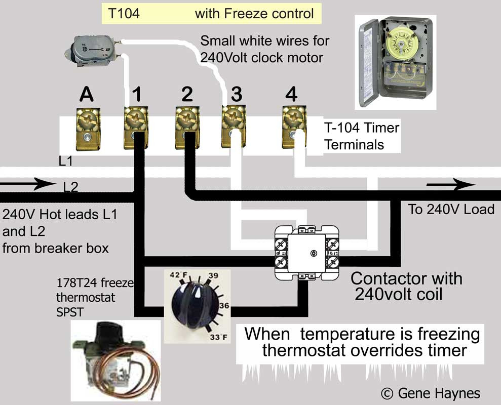
2 line in wires and 2 line out wires to the single speed pump. The speaker wiring diagram and connection guide the basics you need to know speaker wire types. Running pool equipment 24 hours is usually unnecessary and. There are also 2 white wires going from the 2 line in connectors to drive the clock motor. Intermatic pool timer wiring diagram just whats wiring diagram.
 Source: diagramresource.blogspot.com
Shop swimming pool pump timer wiring diagram, choose swimming pool pump timer wiring diagram from top brands, swimming pool pump timer wiring diagram for sale from ebay! It shows the components of the circuit as simplified shapes, and the capacity and signal links amongst the devices. Not merely will it help you achieve your required outcomes more quickly, but also make the entire procedure simpler for everybody. The red and blue cable on the left opening, are coming from the fpl on call box. Swimming pool electrical wiring diagram swimming pool electrical wiring diagram luxury fine pool pump timer wiring diagram electrical circuit file type.
This site is an open community for users to share their favorite wallpapers on the internet, all images or pictures in this website are for personal wallpaper use only, it is stricly prohibited to use this wallpaper for commercial purposes, if you are the author and find this image is shared without your permission, please kindly raise a DMCA report to Us.
If you find this site adventageous, please support us by sharing this posts to your preference social media accounts like Facebook, Instagram and so on or you can also save this blog page with the title pool pump timer wiring diagram by using Ctrl + D for devices a laptop with a Windows operating system or Command + D for laptops with an Apple operating system. If you use a smartphone, you can also use the drawer menu of the browser you are using. Whether it’s a Windows, Mac, iOS or Android operating system, you will still be able to bookmark this website.
Category
Related By Category
- Predator 670 engine wiring diagram Idea
- Frsky x8r wiring diagram information
- Pioneer ts wx130da wiring diagram Idea
- Johnson 50 hp wiring diagram Idea
- Kohler voltage regulator wiring diagram Idea
- Johnson 50 hp outboard wiring diagram information
- Kti hydraulic remote wiring diagram Idea
- Pyle plpw12d wiring diagram information
- Tx9600ts wiring diagram information
- Lifan 50cc wiring diagram information