Pool pump capacitor wiring diagram Idea
Home » Trend » Pool pump capacitor wiring diagram Idea
Your Pool pump capacitor wiring diagram images are available. Pool pump capacitor wiring diagram are a topic that is being searched for and liked by netizens now. You can Download the Pool pump capacitor wiring diagram files here. Find and Download all free images.
If you’re looking for pool pump capacitor wiring diagram images information connected with to the pool pump capacitor wiring diagram keyword, you have come to the right blog. Our website frequently gives you hints for downloading the highest quality video and image content, please kindly hunt and find more informative video articles and images that match your interests.
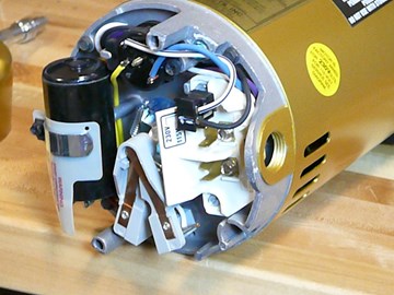
Pool Pump Capacitor Wiring Diagram. Wiring diagram arrives with several easy to adhere to wiring diagram guidelines. Look at the wiring diagram for your specific hvac equipment and find the capacitor where you’ll see its wires and their identities. It includes directions and diagrams for different types of wiring methods and other products like lights, windows, etc. This video shows a diy (by an amateur) diagnosis of a pool pump problem and the replacement of a failing capacitor on the pump motor.disclaimer:
 120V/240V Pool & Sprinkler Motors Testing/Wiring From youtube.com
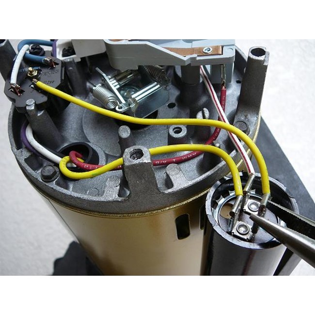
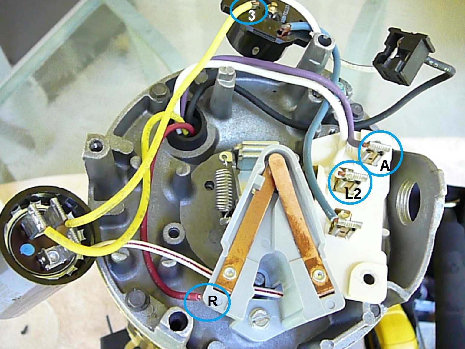
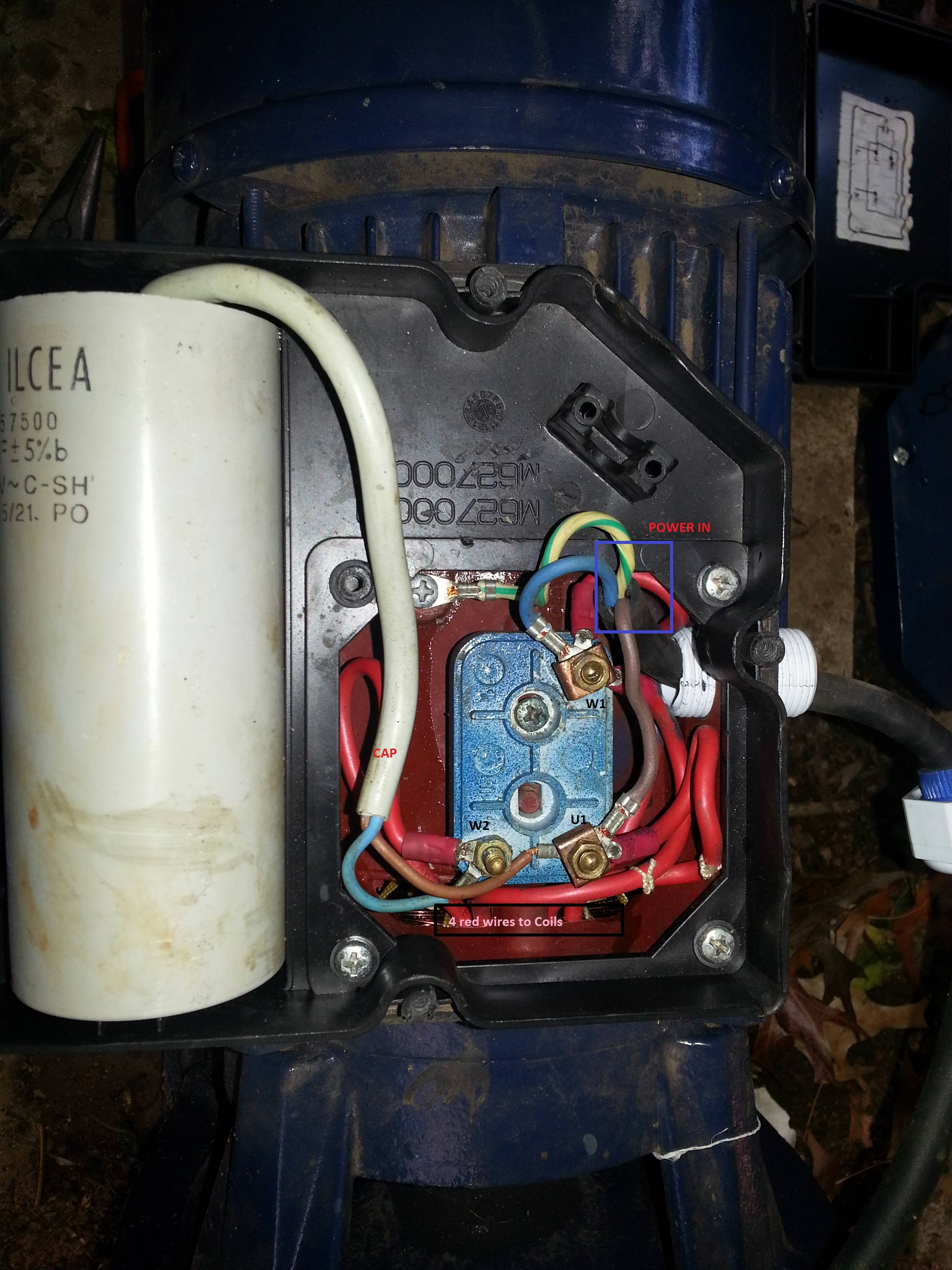
Push the wire terminal on the start capacitor�s second wire onto the run capacitor�s common terminal, often labeled c, com. the wire connected to the motor�s run terminal, marked as r on the motor�s wiring chart, and the wire going to the hot terminal on the load side of the contactor also connects to this run capacitor terminal. There are two things which are going to be present in any single phase motor wiring diagram with capacitor. Not merely will it help you achieve your required outcomes more quickly, but also make the entire procedure simpler for everybody. In this example for hayward pool pumps, red will go to the l1 terminal and black will. It includes directions and diagrams for different types of wiring methods and other products like lights, windows, etc. Replacing the capacitor in my davey pump and although there is a wiring diagram on the pump, there are two wires (blue and light blue) but the digram just says blue for both ?
There are just two things which are going to be present in any pentair pool pump wiring diagram.
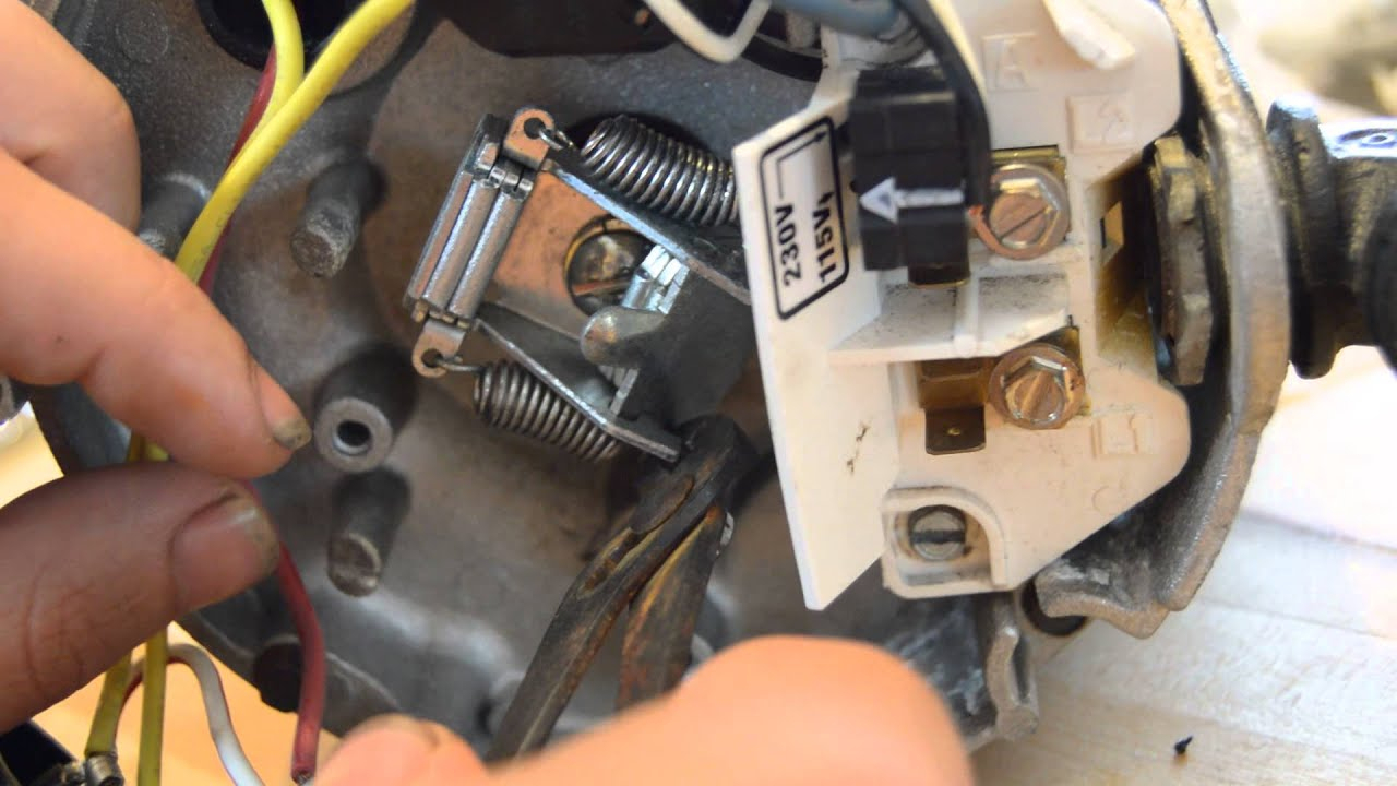
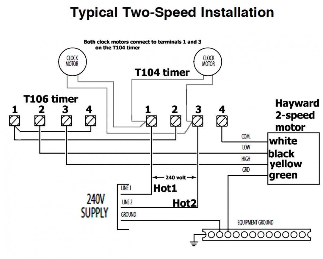
Look at the wiring diagram for your specific hvac equipment and find the capacitor where you’ll see its wires and their identities. Wire diagram for sand filter pump trouble free pool intex setup complete step by guide own the cartridge 15 pools 2 8m3 hr 1000 gph heatpumps4pools sf80110 1 wiring. Pool pumps are wired to run on either 230v or 115v. Lightolier sunrise dimmer wiring diagram. Harris pool pump wiring diagram wiring diagram is a simplified adequate pictorial representation of an electrical circuitit shows the components of the circuit as simplified shapes and the capacity and signal. How to wire intermatic t104 and t103 and t101 timers throughout pool pump timer wiring diagram image size 586 x 350 px.
 Source: diagramweb.net
It really is intended to assist each of the common consumer in developing a proper system. Capacitor also doesnt have a pinout legend that i can see. It includes directions and diagrams for different types of wiring methods and other products like lights, windows, etc. Bm cbb61 capacitor wiring diagram free download 2022 by antone.ruecker. Bought a new century hst 1 hp motor, connected lines to l1 and l2 green to.
 Source: youtube.com
On or near the nameplate is a. There are four common types of residential pool pump motors: Lightolier sunrise dimmer wiring diagram. I am replacing my 1 speed pump which is wired with 110v. The first element is symbol that indicate electric component in the circuit.
 Source: youtube.com
It really is intended to assist each of the common consumer in developing a proper system. I took off the capacitor and after some time, ordered a new replacement. A circuit is usually composed by many components. Check your pool pump owners manual for the correct size. Pool pump timer wiring diagram here you are at our website.
 Source: inyopools.com
Wiring diagram arrives with several easy to adhere to wiring diagram guidelines. There are just two things which are going to be present in any pentair pool pump wiring diagram. July 4, 2021 on 220v pool pump wiring diagram. Not merely will it help you achieve your required outcomes more quickly, but also make the entire procedure simpler for everybody. Find the besttemplates at vincegray2014.
 Source: wiringall.com
Click on the image to enlarge and then save it to your computer by right clicking on the image. Pool pump timer wiring diagram here you are at our website. 2014 vw jetta se fuse diagram; 2004 oz rally lancer radio wiring diagram. It includes directions and diagrams for different types of wiring methods and other products like lights, windows, etc.
 Source: troublefreepool.com
1995 mack fuse panel diagram; Century 1.5 hp motor for hayward wiring diagram. The other thing that you will get a circuit diagram would be traces. Capacitor also doesnt have a pinout legend that i can see. Wiring diagram includes numerous in depth illustrations that show the link of varied products.
 Source: wiringdiagram101.blogspot.com
Capacitor also doesnt have a pinout legend that i can see. A circuit is usually composed by many components. How to wire intermatic t104 and t103 and t101 timers throughout pool pump timer wiring diagram image size 586 x 350 px. Not merely will it help you achieve your required outcomes more quickly, but also make the entire procedure simpler for everybody. On or near the nameplate is a.
 Source: youtube.com
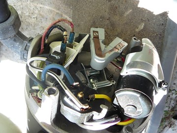
Wire diagram for sand filter pump trouble free pool intex setup complete step by guide own the cartridge 15 pools 2 8m3 hr 1000 gph heatpumps4pools sf80110 1 wiring. Written for dealership mechanics this wiring diagram shows you how to follow the wiring from bumper to bumper. When i try to put it back on, i found there are three wires from the motor: I am replacing my 1 speed pump which is wired with 110v. 2004 ford e150 brake lines diggram;
 Source: inyopools.com
How to wire intermatic t104 and t103 and t101 timers throughout pool pump timer wiring diagram image size 586 x 350 px. 2004 oz rally lancer radio wiring diagram. Wiring diagram arrives with several easy to adhere to wiring diagram guidelines. Not merely will it help you achieve your required outcomes more quickly, but also make the entire procedure simpler for everybody. Knowing how to test a pool pump capacitor can save you time and money when the pump motor fails.
 Source: troubleshooters.com
The first component is symbol that indicate electrical element in the circuit. Wiring diagram includes numerous comprehensive illustrations that show the relationship of assorted items. Wire diagram for sand filter pump trouble free pool intex setup complete step by guide own the cartridge 15 pools 2 8m3 hr 1000 gph heatpumps4pools sf80110 1 wiring. Every day that a pump is down, the likelihood of a lengthy and expensive cleanup increases. How to wire intermatic t104 and t103 and t101 timers throughout pool pump timer wiring diagram image size 586 x 350 px.
 Source: 2020cadillac.com
The first component is symbol that indicate electrical element in the circuit. Most pool pumps use a 220 volt capacitor start induction run csi electric motor wired directly to a pool timer through a flexible conduit or whip. Wiring diagram includes numerous in depth illustrations that show the link of varied products. On or near the nameplate is a. Look at the wiring diagram for your specific hvac equipment and find the capacitor where you’ll see its wires and their identities.
 Source: diagramweb.net
Century 1.5 hp motor for hayward wiring diagram. Harris pool pump wiring diagram wiring diagram is a simplified adequate pictorial representation of an electrical circuitit shows the components of the circuit as simplified shapes and the capacity and signal. An icon used to represent a menu that can be toggled by interacting with this icon. Every day that a pump is down, the likelihood of a lengthy and expensive cleanup increases. 2014 vw jetta se fuse diagram;
 Source: annawiringdiagram.com
These directions will be easy to understand and implement. Push the wire terminal on the start capacitor�s second wire onto the run capacitor�s common terminal, often labeled c, com. the wire connected to the motor�s run terminal, marked as r on the motor�s wiring chart, and the wire going to the hot terminal on the load side of the contactor also connects to this run capacitor terminal. Replacing the capacitor in my davey pump and although there is a wiring diagram on the pump, there are two wires (blue and light blue) but the digram just says blue for both ? Click on the image to enlarge and then save it to your computer by right clicking on the image. A circuit is usually composed by many components.
 Source: schematron.org
Look at the wiring diagram for your specific hvac equipment and find the capacitor where you’ll see its wires and their identities. Split phase, capacitor start, permanent split capacitor and capacitor start/ capacitor run. Pool pumps are wired to run on either 230v or 115v. This video shows a diy (by an amateur) diagnosis of a pool pump problem and the replacement of a failing capacitor on the pump motor.disclaimer: Ford 3000 tractor power steering diagram;

Check your pool pump owners manual for the correct size. Check your pool pump owners manual for the correct size. It shows the parts of the circuit as simplified forms and the power and also signal connections in between the tools. This video shows a diy (by an amateur) diagnosis of a pool pump problem and the replacement of a failing capacitor on the pump motor.disclaimer: An icon used to represent a menu that can be toggled by interacting with this icon.
 Source: inyopools.com
Pool pumps are wired to run on either 230v or 115v. 2014 vw jetta se fuse diagram; When i try to put it back on, i found there are three wires from the motor: Wire diagram for sand filter pump trouble free pool intex setup complete step by guide own the cartridge 15 pools 2 8m3 hr 1000 gph heatpumps4pools sf80110 1 wiring. How to wire intermatic t104 and t103 and t101 timers throughout pool pump timer wiring diagram image size 586 x 350 px.
 Source: annawiringdiagram.com
This video shows a diy (by an amateur) diagnosis of a pool pump problem and the replacement of a failing capacitor on the pump motor.disclaimer: The other thing that you will get a circuit diagram would be traces. Lightolier sunrise dimmer wiring diagram. Troubleshooting a pump motor should begin with testing the capacitor (s). Tomtom one n14644 update free;
 Source: tops-stars.com
Lightolier sunrise dimmer wiring diagram. The first component is symbol that indicate electrical element in the circuit. Maintain, troubleshoot and service a.o. You should see a wiring diagram glued to the inside of the air handler cabinet or to the inside of the blower compartment door. Push the wire terminal on the start capacitor�s second wire onto the run capacitor�s common terminal, often labeled c, com. the wire connected to the motor�s run terminal, marked as r on the motor�s wiring chart, and the wire going to the hot terminal on the load side of the contactor also connects to this run capacitor terminal.
This site is an open community for users to share their favorite wallpapers on the internet, all images or pictures in this website are for personal wallpaper use only, it is stricly prohibited to use this wallpaper for commercial purposes, if you are the author and find this image is shared without your permission, please kindly raise a DMCA report to Us.
If you find this site convienient, please support us by sharing this posts to your favorite social media accounts like Facebook, Instagram and so on or you can also bookmark this blog page with the title pool pump capacitor wiring diagram by using Ctrl + D for devices a laptop with a Windows operating system or Command + D for laptops with an Apple operating system. If you use a smartphone, you can also use the drawer menu of the browser you are using. Whether it’s a Windows, Mac, iOS or Android operating system, you will still be able to bookmark this website.
Category
Related By Category
- Predator 670 engine wiring diagram Idea
- Frsky x8r wiring diagram information
- Pioneer ts wx130da wiring diagram Idea
- Johnson 50 hp wiring diagram Idea
- Kohler voltage regulator wiring diagram Idea
- Johnson 50 hp outboard wiring diagram information
- Kti hydraulic remote wiring diagram Idea
- Pyle plpw12d wiring diagram information
- Tx9600ts wiring diagram information
- Lifan 50cc wiring diagram information