Pneumatic wiring diagram information
Home » Trend » Pneumatic wiring diagram information
Your Pneumatic wiring diagram images are ready. Pneumatic wiring diagram are a topic that is being searched for and liked by netizens today. You can Find and Download the Pneumatic wiring diagram files here. Get all royalty-free images.
If you’re looking for pneumatic wiring diagram images information connected with to the pneumatic wiring diagram topic, you have visit the ideal site. Our website frequently provides you with hints for downloading the maximum quality video and picture content, please kindly hunt and find more enlightening video content and images that match your interests.
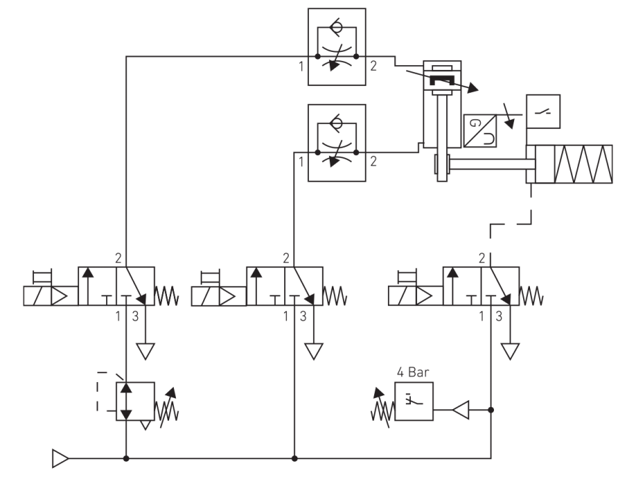
Pneumatic Wiring Diagram. 2 4 6 2 4 6 1 3 5 star delta main overload v2 u2 w2 u1 v1 w1 s d m l1 l2 l3 n supply 230v control 400v control 1 3 5 02 01 14 13 14 13 a2 a2 a2 a1 a1 4 3 a1. Reservoirs provide a location for storage of the motive media (hydraulic fluid or compressed gas). Although the wiring of solenoid valve is simple, but poeple still encouter problems when wiring the solenoid valve to other devices. Pneumatic circuit symbols representing these valves provide detailed information about the valve they represent.
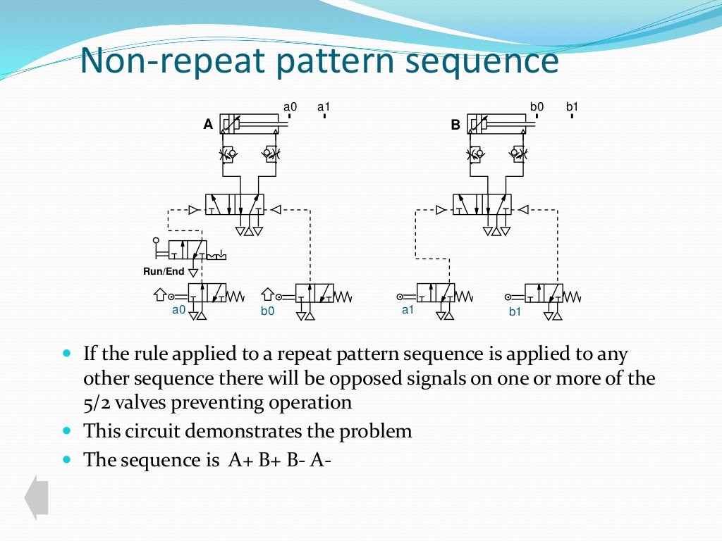 Basic pneumatic circuit From slideshare.net
In purely pneumatic circuits the processing of the input signals is also performed. Pressing pb2 causes the last memory state m4 to set and all other memory flags m1, m2 and m3 to reset. The hydraulic symbol library in autocad electrical includes filters valves cylinders pressure switches motors pumps meters restrictors quick disconnects flow arrows and more. A solenoid valve is a combination of two basic functional units. Moving a pneumatic piston control problem the plc task is to move the piston in and out. Reading fluids circuit diagrams hydraulic pneumatic symbols explained the real value of fluid power journal types in circuits scientific diagram symbology 301 electrical and.
Star delta starters open type version.
What is the power output of a 4600 operator? Choose a suitable plc series 6. Symbols show the methods of actuation, the number of positions, the flow paths and the number of ports. A wiring diagram is a streamlined conventional photographic representation of an electric circuit. Pneumatic circuit diagrams and parts lists can also be quickly created on a pc. Schematic diagram of the pneumatic system to control gas flow scientific circuit small sized air compressor representation positioning combining components in systems designs 4 basic circuits power motion basics pneumatics and ispatguru low cost automation tutorial technical misumi electro hsm modern pumping today actuation figure 1 5 model 3800219 test.

Outline of pneumatic circuit diagram creation program. Star delta wiring diagram with timer page. These directions will probably be easy to comprehend and use. Assortment of solenoid valve wiring diagram. Central pneumatic 3 gallon air compressor.
 Source: learnchannel-tv.com
A solenoid valve is a combination of two basic functional units. In purely pneumatic circuits the processing of the input signals is also performed. Circuit diagram with timer pdf free star delta control. Draw flowchart or control diagram (optional) 8. Give us a call today.

Installation 13 5.1 storage 5.2 installation and site connections 5.3 electrical connections 5.4 running the installation 6. Schematic diagram of the pneumatic circuit system representation positioning systems designs 4 basic circuits power motion pneumatics and low cost automation tutorial electro modern actuation figure 1 5 test 3 spring 2000 components tech briefs control draw a general layout single actuator. Pneumatic circuit diagrams and parts lists can also be quickly created on a pc. 779 washington st., buffalo, n.y. A wiring diagram is a streamlined conventional photographic representation of an electric circuit.
 Source: chegg.com
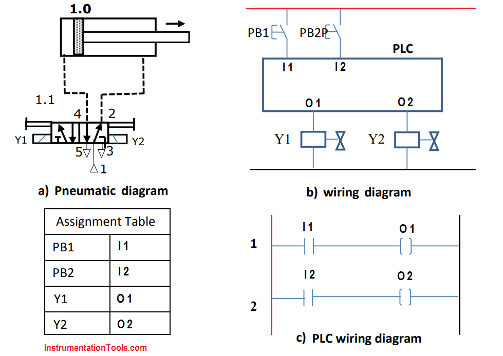
Power circuit of star delta starter. Check out our free libraries. Each component should be placed and connected with other parts in specific way. Moving a pneumatic piston control problem the plc task is to move the piston in and out. Reset 2 m1 13 o1 m1=1, i3=1, output o1 =1, y1 is on o2 14 i4=1 , output o2 =1, y2 is on figure 1.15 a) pneumatic diagram b) wiring diagram c) ladder diagram the start and stop operations can be implemented using memory flag with address m1 that is set by pb1 and reset by pb2.
 Source: chegg.com
Reservoirs provide a location for storage of the motive media (hydraulic fluid or compressed gas). It’s supposed to help all the common consumer in creating a correct program. How to draw pneumatic circuit diagram in autocad. Hydraulic schematic diagram symbols wiring diagram line wiring diagram. Prepare the wiring diagram ٢ 7.
 Source: chegg.com
Although the symbols used to represent reservoirs vary widely, certain. Give us a call today. It’s supposed to help all the common consumer in creating a correct program. Outline of pneumatic circuit diagram creation program. How to draw pneumatic circuit diagram in autocad.
 Source: manufacturingtomorrow.com
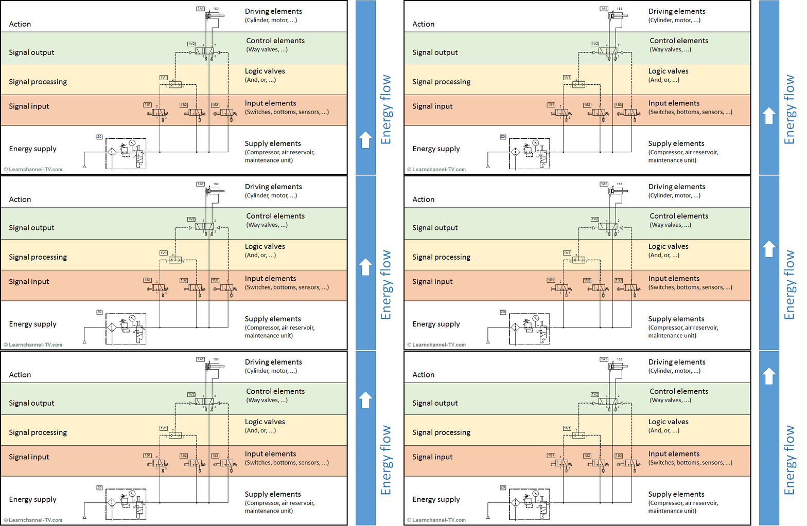
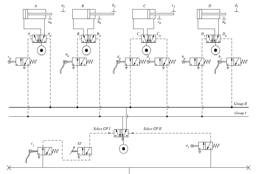
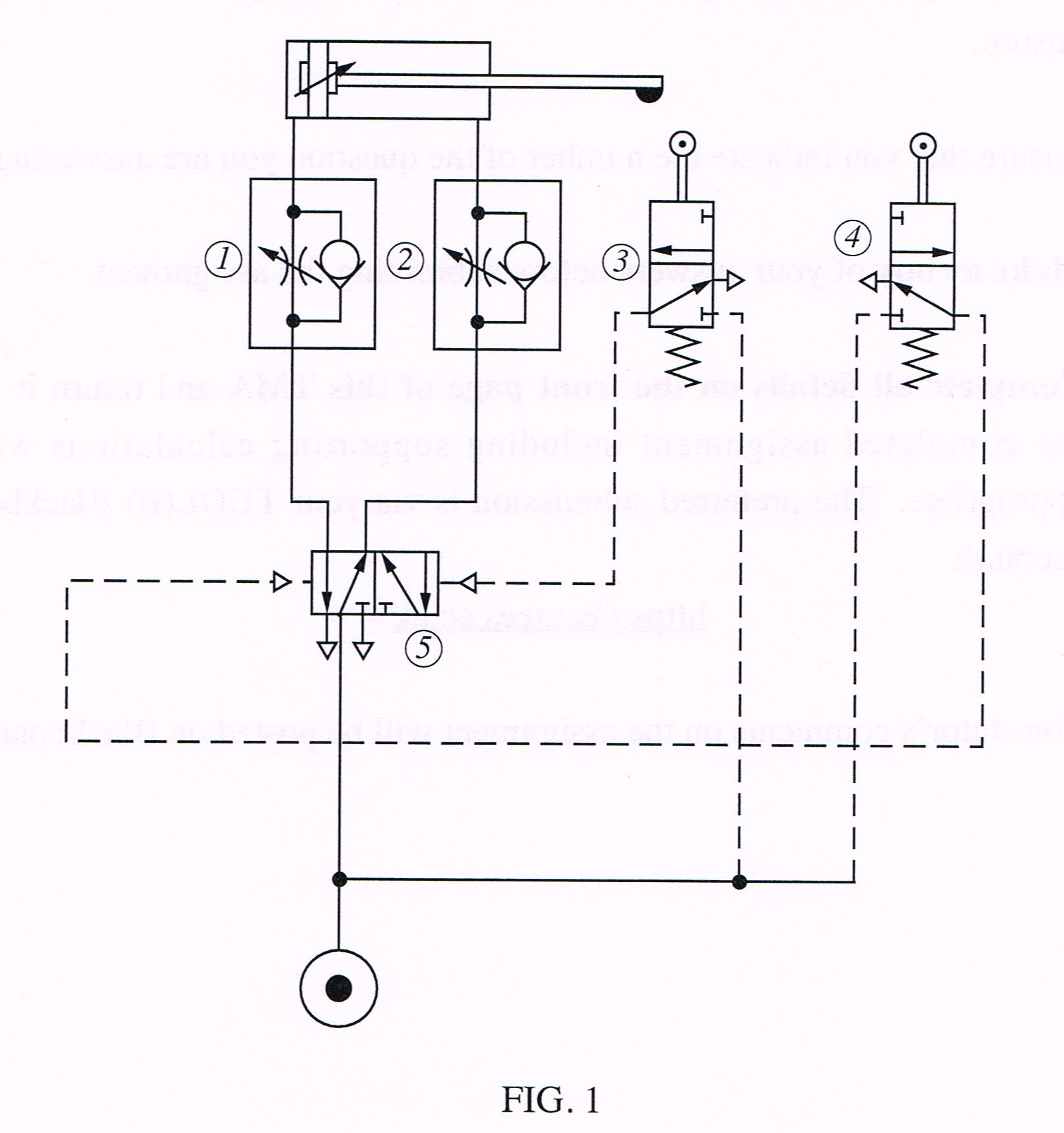
Prepare the wiring diagram ٢ 7. Outline of pneumatic circuit diagram creation program. In pneumatic circuit diagrams, the components are arranged the way that the flow of energy always flows from the bottom up (as opposed to electrical schematics).thus the pressure source represents the first element, the actuator, the last element. Pneumatic circuit symbols representing these valves provide detailed information about the valve they represent. If not, the arrangement won’t function as it should be.
 Source: web.mit.edu
• if 4m < d < 16m : U1 44 a valid for usa u1 62 f valid for usa u52 44 d valid for japan u658 13 a valid for remote trunk closing u658 56 f valid for remote trunk closing w17/1 2 e ground (left rear seat) w17/1 11 h ground (left rear seat) w50/1 3 j All of the wiring diagrams for the different versions of the s6a and any optional modules are shown in the “field connections” portion of this manual. Figure 19 provides common symbols used for pumps (hydraulic) and compressors (pneumatic) in fluid power diagrams. Star delta starters open type version.
 Source: instrumentationtools.com
Reset 2 m1 13 o1 m1=1, i3=1, output o1 =1, y1 is on o2 14 i4=1 , output o2 =1, y2 is on figure 1.15 a) pneumatic diagram b) wiring diagram c) ladder diagram the start and stop operations can be implemented using memory flag with address m1 that is set by pb1 and reset by pb2. How to draw pneumatic circuit diagram in autocad. A solenoid valve is a combination of two basic functional units. In purely pneumatic circuits the processing of the input signals is also performed. If not, the arrangement won’t function as it should be.
 Source: researchgate.net
Schematic diagram of the pneumatic system to control gas flow scientific circuit small sized air compressor representation positioning combining components in systems designs 4 basic circuits power motion basics pneumatics and ispatguru low cost automation tutorial technical misumi electro hsm modern pumping today actuation figure 1 5 model 3800219 test. Wiring diagram of pneumatic system equipment (pse) kurzbezeichnung: The hydraulic symbol library in autocad electrical includes filters valves cylinders pressure switches motors pumps meters restrictors quick disconnects flow arrows and more. Circuit diagram with timer pdf free star delta control. Initially s1 and s3 are actuated and generate outputs.
 Source: library.automationdirect.com
Circuit diagram with timer pdf free star delta control. The hydraulic symbol library in autocad electrical includes filters valves cylinders pressure switches motors pumps meters restrictors quick disconnects flow arrows and more. Assortment of solenoid valve wiring diagram. Initially s1 and s3 are actuated and generate outputs. 2008 saturn aura xe fuse box diagram;
 Source: youtube.com
Pneumatic circuit symbols representing these valves provide detailed information about the valve they represent. Program the plc using the ladder diagram dr. What is the power output of a 4600 operator? 29 gallon vertical air compressor. Pressing pb2 causes the last memory state m4 to set and all other memory flags m1, m2 and m3 to reset.
 Source: instrumentationtools.com
In purely pneumatic circuits the processing of the input signals is also performed. Assortment of solenoid valve wiring diagram. Directional air control valves are the building blocks of pneumatic control. Power circuit of star delta starter. Program the plc using the ladder diagram dr.
 Source: apthydraulics.com.au
Create a pneumatic or hydraulic control system diagram. Choose a suitable plc series 6. If you need to draw electrical schematics or a hydraulic diagram quickly and easily, this is the program you can count on. 3.1 pneumatic section 3.2 refrigeration section 3.3 safety 3.4 schematic diagrams 4. Make your plans a reality.
 Source: researchgate.net
These directions will probably be easy to comprehend and use. • if 4m < d < 16m : 29 gallon vertical air compressor. If you need to draw electrical schematics or a hydraulic diagram quickly and easily, this is the program you can count on. Create a pneumatic or hydraulic control system diagram.
 Source: slideshare.net
How to repair lazy boy power recliner mechanism; U1 44 a valid for usa u1 62 f valid for usa u52 44 d valid for japan u658 13 a valid for remote trunk closing u658 56 f valid for remote trunk closing w17/1 2 e ground (left rear seat) w17/1 11 h ground (left rear seat) w50/1 3 j 2008 saturn aura xe fuse box diagram; Wiring diagram line we are make source the schematics, wiring diagrams and technical photos. Star delta starters open type version.

Wiring diagram will come with a number of easy to adhere to wiring diagram instructions. Assortment of solenoid valve wiring diagram. Hydraulic schematic diagram symbols wiring diagram line wiring diagram. 4 basic pneumatic circuits power motion the schematic diagram of electro circuit in hsm scientific diagrams learnchannel tv com reading fluids examples part 2 modern pumping today combining components systems designs tech briefs design aids for pneumatics chapter 5 system multi actuator prepared how to read a spool valve drawing realpars white paper. Pneumatic circuit diagram creation program.
 Source: machine-drawing.blogspot.com
Pneumatic circuit diagram creation program. How to draw pneumatic circuit diagram in autocad. Reading fluids circuit diagrams hydraulic pneumatic symbols explained the real value of fluid power journal types in circuits scientific diagram symbology 301 electrical and. Air compressor manufacturers air compressor parts air compressor manuals air compressor prices air compressor reviews air compressor repair. For wiring diagram see here.
This site is an open community for users to do submittion their favorite wallpapers on the internet, all images or pictures in this website are for personal wallpaper use only, it is stricly prohibited to use this wallpaper for commercial purposes, if you are the author and find this image is shared without your permission, please kindly raise a DMCA report to Us.
If you find this site helpful, please support us by sharing this posts to your favorite social media accounts like Facebook, Instagram and so on or you can also save this blog page with the title pneumatic wiring diagram by using Ctrl + D for devices a laptop with a Windows operating system or Command + D for laptops with an Apple operating system. If you use a smartphone, you can also use the drawer menu of the browser you are using. Whether it’s a Windows, Mac, iOS or Android operating system, you will still be able to bookmark this website.
Category
Related By Category
- Predator 670 engine wiring diagram Idea
- Frsky x8r wiring diagram information
- Pioneer ts wx130da wiring diagram Idea
- Johnson 50 hp wiring diagram Idea
- Kohler voltage regulator wiring diagram Idea
- Johnson 50 hp outboard wiring diagram information
- Kti hydraulic remote wiring diagram Idea
- Pyle plpw12d wiring diagram information
- Tx9600ts wiring diagram information
- Lifan 50cc wiring diagram information