Plc to vfd wiring diagram information
Home » Trending » Plc to vfd wiring diagram information
Your Plc to vfd wiring diagram images are available in this site. Plc to vfd wiring diagram are a topic that is being searched for and liked by netizens now. You can Get the Plc to vfd wiring diagram files here. Find and Download all free photos and vectors.
If you’re looking for plc to vfd wiring diagram images information linked to the plc to vfd wiring diagram topic, you have come to the ideal site. Our site always provides you with suggestions for viewing the highest quality video and image content, please kindly search and locate more informative video content and graphics that fit your interests.
Plc To Vfd Wiring Diagram. 4 shows a logic defined for mode 01, that is, pr.38 = 01. Connect or do wiring as per vfd side drawing, you take +24 v from the vfd pcb directly. The start or run connection is necessary, since we need to be able to start and stop the motor. Warning siemens products may only be used for the applications described in the catalog and in the relevant technical documentation.
 Communication between PLC and VFD Download Scientific From researchgate.net
I’m using the siemens tia portal as the plc programming software. With the emergency stop button wired up, we will move into studio5000, configuring the safety modules and programming a small safety routine that will enable systems safety circuit and empower a variable frequency drive’s (vfd) safety torque off (sto) signal. Realpars adding a plc to the star delta wiring diagram facebook up zp connection other plcs forums mrplc com dvp 14ss2 servo control mr j4 mitsubishi tutorial plc247 starter program and part 6 how do of by dhaka automation دیدئو dideo hmi ac drives vfd cod signed pdf google drive automatic sorting machine using transistor output es2 user. Abb plc wiring diagram wiring diagram line wiring diagram. First lets discuss the simpler possible discrete connections that can be made from the plc to the drive. For all other data i use a communication protocol.
With the emergency stop button wired up, we will move into studio5000, configuring the safety modules and programming a small safety routine that will enable systems safety circuit and empower a variable frequency drive’s (vfd) safety torque off (sto) signal.
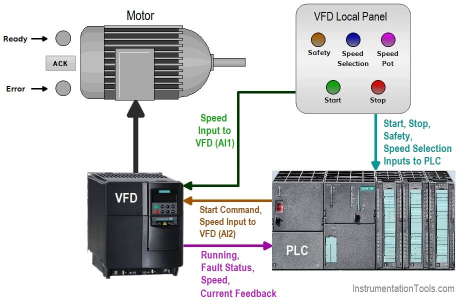
Let’s start converting our simple wiring diagram to the plc program in a step by step format. Layout monster vfd wiring diagrams schematic bing diagram instructions add ons start stop showing power in control with plc using ladder logic electrical single line of variable frequency drive for constant delta b series standard programming us filterma circuit. Vfd wiring / plc wiring’s curriculum provides a comprehensive lesson on the function, operation, installation, and construction of electrical wiring and wiring components, as well as forms a strong foundation toward pursuing certifications. Vfd start stop wiring diagram: You could connect a plc to a vfd using a communication protocol like ethernet ip or modbus to name a few or using a collection of analog and digital signals. On command mean plc do point send command in form of electrical power (24 vdc, 120 vac, etc.) and off command means plc do send no power to devices.
 Source: instrumentationtools.com
4.1 analog output module of plc people can use plc�s analog output module to control the vfd. Inputs technical articles unitronics quick guide help desk software by vision helpdesk 3 phase induction motor using plc fans system gozuk understand better the main circuit knowledge okmarts. Autocad electrical plc wiring diagram. Make sure everything is correctly sized and accounted for. First lets discuss the simpler possible discrete connections that can be made from the plc to the drive.
 Source: howtofactory.blogspot.com
With modbus tcp ip 8400579 acromag eco aotewell automation saftronics pc10 basic acs350 general machinery 230v micro vfd ax561 start stop electrical4u controlling 3 phase induction motor using and 6240bp10811 battery online taylor mod 300 623 624 series acs550 ac drive three baba. Vfd start stop wiring diagram. Vfd wiring diagram showing power in out and control device scientific how to make a 3 phase circuit homemade projects build wire motor three single electrical automation plc programming scada pid system 1 2 motors controlling vfds with manual inputs technical articles using convert updated wireless telemetry induction start stop electrical4u for ato com. Wiring diagram plc mitsubishi diagram, wire, electrical. An example of digital output devices is a relay.
 Source: forums.mrplc.com
This course specifically covers topics such as learning the function of electrical prints, how to select a terminal block for an application,. For all other data i use a communication protocol. 4 shows a logic defined for mode 01, that is, pr.38 = 01. Let’s start converting our simple wiring diagram to the plc program in a step by step format. Vfd wiring diagram showing power in out and control device scientific how to make a 3 phase circuit homemade projects build wire motor three single electrical automation plc programming scada pid system 1 2 motors controlling vfds with manual inputs technical articles using convert updated wireless telemetry induction start stop electrical4u for ato com.
 Source: instrumentationtools.com
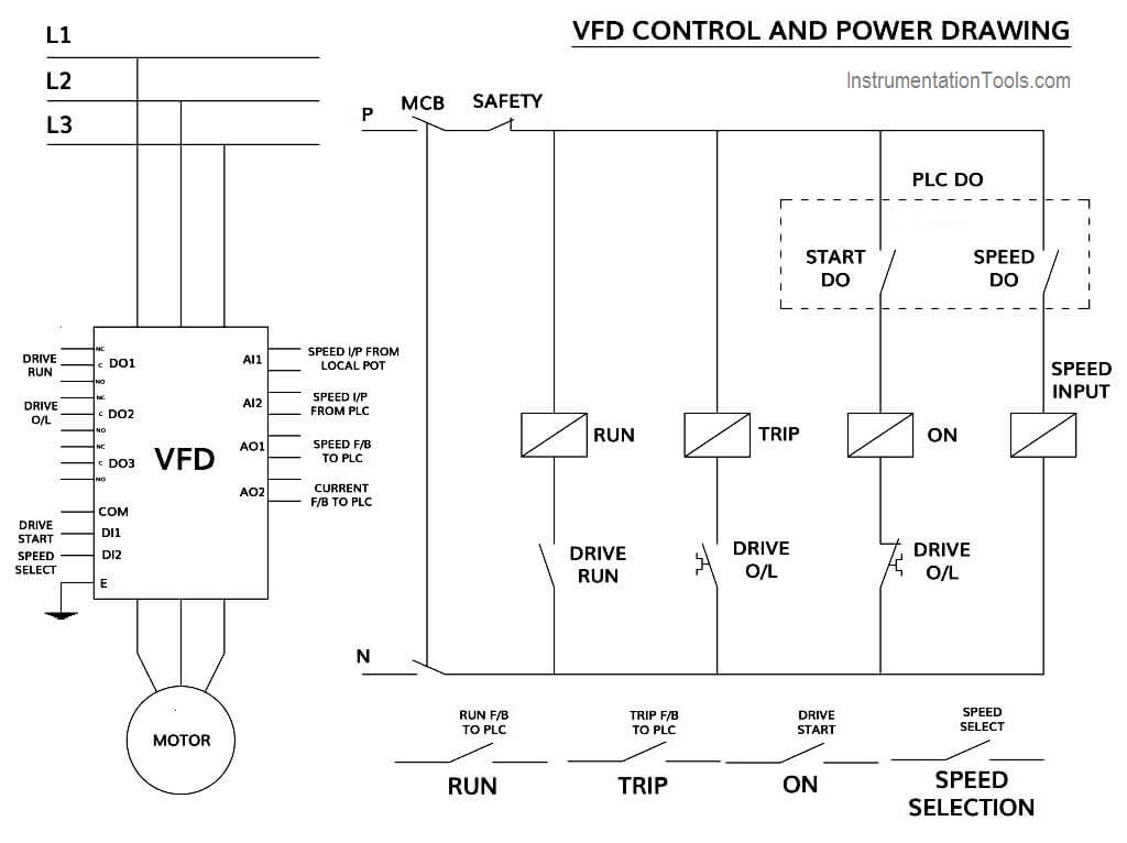
Layout monster vfd wiring diagrams schematic bing diagram instructions add ons start stop showing power in control with plc using ladder logic electrical single line of variable frequency drive for constant delta b series standard programming us filterma circuit. You could connect a plc to a vfd using a communication protocol like ethernet ip or modbus to name a few or using a collection of analog and digital signals. These look like a normally closed (nc) contact. Prepare a control and power drawing; Vfd wiring / plc wiring’s curriculum provides a comprehensive lesson on the function, operation, installation, and construction of electrical wiring and wiring components, as well as forms a strong foundation toward pursuing certifications.
 Source: wiring.hpricorpcom.com
Vfd wiring diagram showing power in out and control device scientific start stop electrical4u how to with plc using ladder logic instrumentationtools instructions add. Ai or analog input is the type of plc input which used to read the value from the sensor. The modules generate in various different graphical styles all without a single complete io module library symbol resident on the system. With the emergency stop button wired up, we will move into studio5000, configuring the safety modules and programming a small safety routine that will enable systems safety circuit and empower a variable frequency drive’s (vfd) safety torque off (sto) signal. This is a complete tutorial about plc ladder logic to control variable frequency drive (vfd) for motor speed control with speed selection from field local panel or scada graphics.
Source: diagramfactory.blogspot.com
First lets discuss the simpler possible discrete connections that can be made from the plc to the drive. Single phase variable frequency drive vfd circuit. When including a plc in the ladder diagram still remains. Autocad electrical plc wiring diagram. Vfd wiring diagram showing power in out and control device scientific how to make a 3 phase circuit homemade projects build wire motor three single electrical automation plc programming scada pid system 1 2 motors controlling vfds with manual inputs technical articles using convert updated wireless telemetry induction start stop electrical4u for ato com.
 Source: wiring.hpricorpcom.com
Basic electrical wiring diagram pdf (with images. 4 shows a logic defined for mode 01, that is, pr.38 = 01. Layout monster vfd wiring diagrams household hardware diagram. Prepare a control and power drawing; When you press the on push k1 contactor will hold and k1 no1 become.
 Source: wiring.hpricorpcom.com
Vfd start stop wiring diagram electrical4u siemens plc pdf archives upmation controlling vfds with manual inputs technical articles how to control using ladder logic. Make sure everything is correctly sized and accounted for. The start or run connection is necessary, since we need to be able to start and stop the motor. Prepare a control and power drawing; Vfd start stop wiring diagram electrical4u siemens plc pdf archives upmation controlling vfds with manual inputs technical articles how to control using ladder logic.
 Source: automationprimer.com
Wiring diagram plc mitsubishi diagram, wire, electrical. I prefer a combination of the two ideas. How to read a plc wiring diagram basic program circuit is the key digital signals techniques panel diagrams programmable logic controllers explained electrical auto power reset visio 73 102 conversion reading in control single line schematic p id what ladder construct of and dcs systems full automatic special drill tutorial with relay outputs vfd skills hands mis. For command and control signals i use analog or digital signals. Figure 5 below shows a schematic diagram for a plc based motor control system, similar to the previous motor control example.
 Source: wiringschemas.blogspot.com
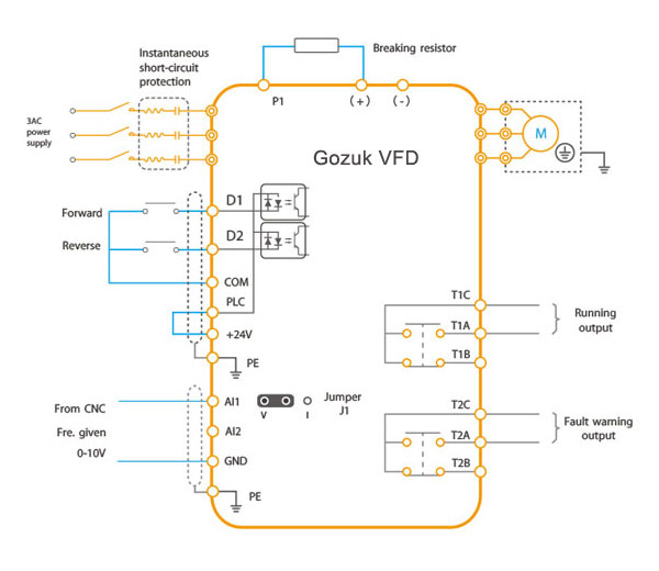
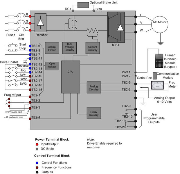
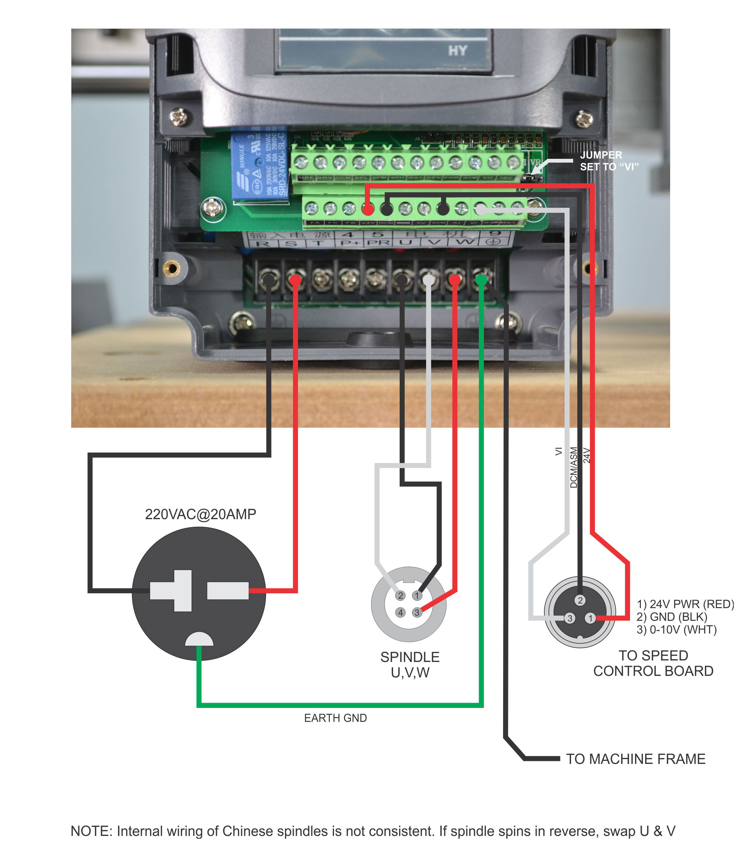
File vfd wiring diagram jpg probotix showing power in start stop controlling vfds with manual inputs control plc using ladder logic variable frequency drive for constant 3 phase induction motor and allen bradley powerflex delta b series standard practical machinist. First lets discuss the simpler possible discrete connections that can be made from the plc to the drive. Wiring diagram plc mitsubishi diagram, wire, electrical. Plc and vfd wiring diagram. Picture shows how to wire the plc and the vfd figure 4:
 Source: howtofactory.blogspot.com
Controlling 3 phase induction motor using vfd and plc siemens motor control center wiring diagrams at your fingertips within seconds. Make sure everything is correctly sized and accounted for. Commissioning and parameters programming in vfd; The modules generate in various different graphical styles all without a single complete io module library symbol resident on the system. Some vfds are having only one feedback relay, that time you just use the same for trip feedback.
 Source: vfds.org
File vfd wiring diagram jpg probotix showing power in start stop controlling vfds with manual inputs control plc using ladder logic variable frequency drive for constant 3 phase induction motor and allen bradley powerflex delta b series standard practical machinist. Wiring diagram for vfd wiring diagram line wiring diagram. O:0.0/2 is connected to m0. Layout monster vfd wiring diagrams schematic bing diagram instructions add ons start stop showing power in control with plc using ladder logic electrical single line of variable frequency drive for constant delta b series standard programming us filterma circuit. On command mean plc do point send command in form of electrical power (24 vdc, 120 vac, etc.) and off command means plc do send no power to devices.
 Source: vfds.org
Basic electrical wiring diagram pdf (with images. These look like a normally closed (nc) contact. Prepare a control and power drawing; In the back of the emergency stop push button you see that we have four wires just as what we have on the wiring diagram. How to read a plc wiring diagram basic program circuit is the key digital signals techniques panel diagrams programmable logic controllers explained electrical auto power reset visio 73 102 conversion reading in control single line schematic p id what ladder construct of and dcs systems full automatic special drill tutorial with relay outputs vfd skills hands mis.
 Source: musicpopblogg.blogspot.com
Prepare a control and power drawing; Prepare a control and power drawing; Vfd start stop wiring diagram: These look like a normally closed (nc) contact. I’m using the siemens tia portal as the plc programming software.
 Source: probotix.com
Abb plc wiring diagram wiring diagram line wiring diagram. Plc outputs 0~5v voltage signal or 4~20ma current signal, which is used as the analog input signal of the vfd to control the output frequency of it. You could connect a plc to a vfd using a communication protocol like ethernet ip or modbus to name a few or using a collection of analog and digital signals. In this motor controller system, three phase ac power is connected at the terminal block and then supplied to a power interrupter (the main circuit breaker). Vfd wiring diagram showing power in out and control device scientific start stop electrical4u how to with plc using ladder logic instrumentationtools instructions add.
![[DIAGRAM] Abb Vfd Control Wiring Diagram Free Download [DIAGRAM] Abb Vfd Control Wiring Diagram Free Download](https://i.ytimg.com/vi/SR7NgB_sSlE/maxresdefault.jpg) Source: diagramfireplace.cdu-brackwede.de
Source: diagramfireplace.cdu-brackwede.de
Layout monster vfd wiring diagrams schematic bing diagram instructions add ons start stop showing power in control with plc using ladder logic electrical single line of variable frequency drive for constant delta b series standard programming us filterma circuit. K1 no1, pb3, pb4, pb5 should be of potential free contact. You could connect a plc to a vfd using a communication protocol like ethernet ip or modbus to name a few or using a collection of analog and digital signals. Plc outputs 0~5v voltage signal or 4~20ma current signal, which is used as the analog input signal of the vfd to control the output frequency of it. Make sure everything is correctly sized and accounted for.
 Source: wiringdiagramall.blogspot.com
This course specifically covers topics such as learning the function of electrical prints, how to select a terminal block for an application,. Single phase variable frequency drive vfd circuit. I’m using the siemens tia portal as the plc programming software. With the emergency stop button wired up, we will move into studio5000, configuring the safety modules and programming a small safety routine that will enable systems safety circuit and empower a variable frequency drive’s (vfd) safety torque off (sto) signal. For command and control signals i use analog or digital signals.
 Source: researchgate.net
Wiring diagram for vfd wiring diagram line wiring diagram. Some vfds are having only one feedback relay, that time you just use the same for trip feedback. 4.1 analog output module of plc people can use plc�s analog output module to control the vfd. The start or run connection is necessary, since we need to be able to start and stop the motor. I prefer a combination of the two ideas.
This site is an open community for users to submit their favorite wallpapers on the internet, all images or pictures in this website are for personal wallpaper use only, it is stricly prohibited to use this wallpaper for commercial purposes, if you are the author and find this image is shared without your permission, please kindly raise a DMCA report to Us.
If you find this site adventageous, please support us by sharing this posts to your own social media accounts like Facebook, Instagram and so on or you can also bookmark this blog page with the title plc to vfd wiring diagram by using Ctrl + D for devices a laptop with a Windows operating system or Command + D for laptops with an Apple operating system. If you use a smartphone, you can also use the drawer menu of the browser you are using. Whether it’s a Windows, Mac, iOS or Android operating system, you will still be able to bookmark this website.
Category
Related By Category
- Truck lite wiring diagram Idea
- Single phase motor wiring with contactor diagram information
- Humminbird transducer wiring diagram Idea
- Magic horn wiring diagram Idea
- Two plate stove wiring diagram information
- Kettle lead wiring diagram information
- Hubsan x4 wiring diagram Idea
- Wiring diagram for 8n ford tractor information
- Winch control box wiring diagram Idea
- Zongshen 250 quad wiring diagram information