Plc input output wiring diagram information
Home » Trend » Plc input output wiring diagram information
Your Plc input output wiring diagram images are available. Plc input output wiring diagram are a topic that is being searched for and liked by netizens today. You can Find and Download the Plc input output wiring diagram files here. Get all royalty-free images.
If you’re looking for plc input output wiring diagram images information related to the plc input output wiring diagram keyword, you have come to the right blog. Our site frequently gives you suggestions for seeing the maximum quality video and picture content, please kindly surf and find more informative video articles and graphics that match your interests.
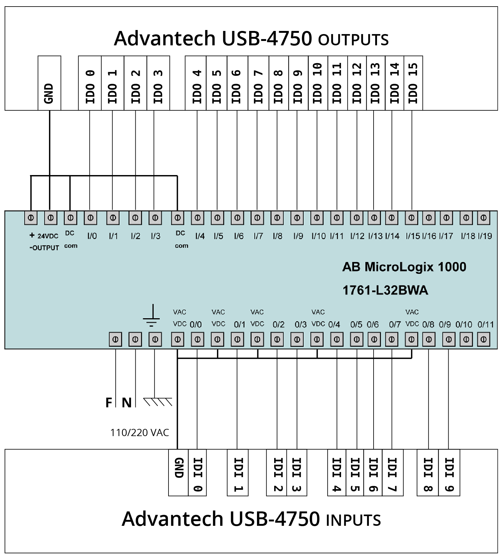
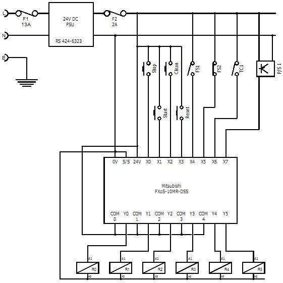
Plc Input Output Wiring Diagram. Cpusr60 wiring diagram figure 6. Selectable output with a 12mm sensing distance. Programs modern pdf 3 azis muslim academia edu block d e notes systems automation introduction what is hmiscu analog inputs outputs faqs schneider electric spain architecture connect rs485 in programmers home facebook are major instrumentation vfd skills. The electrical panel wiring diagram above displays an example of a transformer and a power supply used within a plc system.
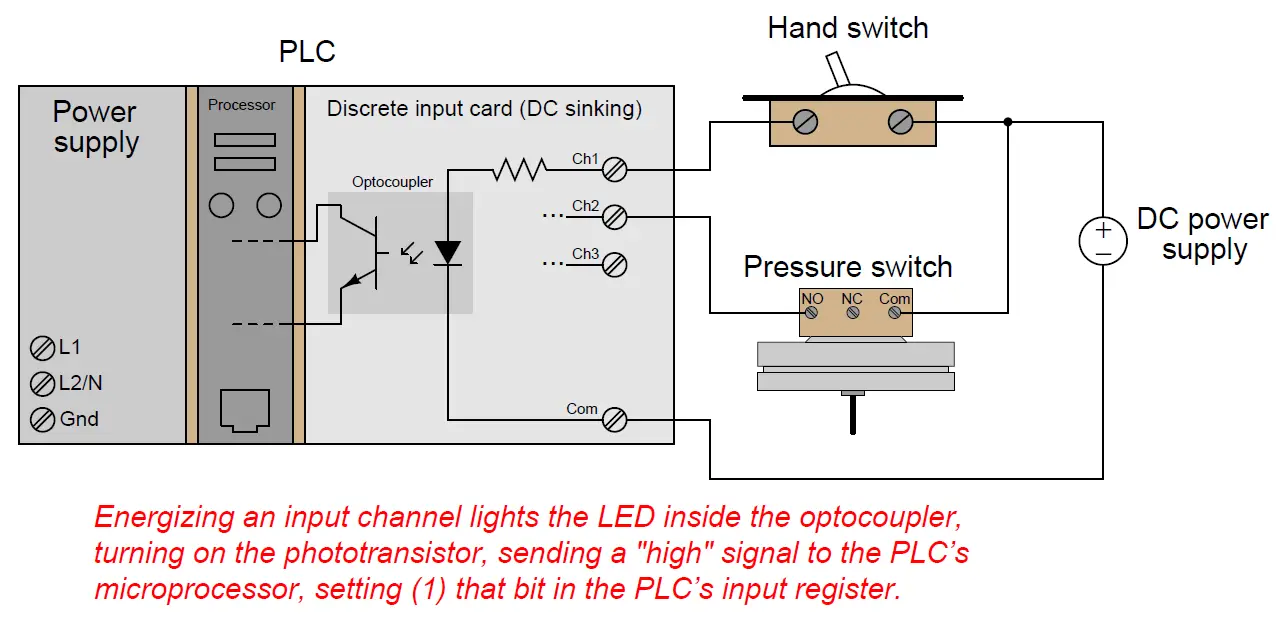 PLC Digital Input and Digital Output Modules PLC From instrumentationtools.com
The green led will then blink indicating that the output is off. Now what output or what input can be in any machine depending on the various processes. Remove and lock out input power from the controller and i/o before any plc installation and wiring begins. Selectable output with a 12mm sensing distance. Plc inputs can be connect in either sink mode or so. The electrical panel wiring diagram above displays an example of a transformer and a power supply used within a plc system.
A legacy model, most possibly you are not using this model.
Cpusr40 wiring diagram figure 3. Siemens factory i o an allen bradley micro820 inputs outputs or micro800 micro830 micro850 micro870 tw controls input output engineers community of switches relays the rslogix 500 analog circuits programming 0 10vdc 4 20ma plcs engineer on disk dcs systems di do ai ao s7 200smart series electronic paper adding star. We will be wiring a 22mm captron pushbutton to a click plc. That means that the sensor can be wired as positive (sourcing) or negative (sinking) switch. Programs modern pdf 3 azis muslim academia edu block d e notes systems automation introduction what is hmiscu analog inputs outputs faqs schneider electric spain architecture connect rs485 in programmers home facebook are major instrumentation vfd skills. Now what are the inputs?
 Source: researchgate.net
It will be represented with an examine off bit. Upon activating the sensor for half a second output on the click plc will turn on. 100 or less to the grounding terminal on the fx3gcfx3uc plc main unit with a wire as thick as possible. Plc input output wiring diagram engineers community advantech for allen bradley factory i o full automatic special drill according to io port scientific siemens how wire discrete dc sensors part 1 realpars diagrams digital signals techniques guidelines installation and connection precautions eep an micro820 inputs outputs or a micro800 micro830. Siemens factory i o an allen bradley micro820 inputs outputs or micro800 micro830 micro850 micro870 tw controls input output engineers community of switches relays the rslogix 500 analog circuits programming 0 10vdc 4 20ma plcs engineer on disk dcs systems di do ai ao s7 200smart series electronic paper adding star.
 Source: pinterest.com
Cpusr60 wiring diagram figure 6. Before you start wiring any plc analog module i highly recommend that you not only read the manual, but also know what type of signal you’re dealing with. I’m using the siemens tia portal as the plc programming software. Perform class d grounding grounding resistance. Do not wire vacant terminals externally.
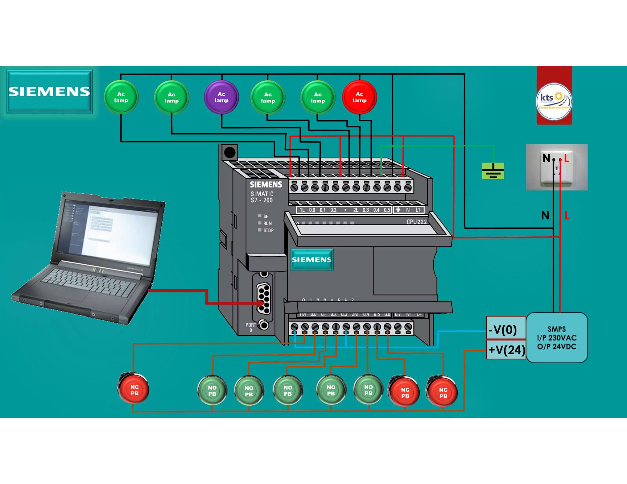 Source: kavisatechsolutions.com
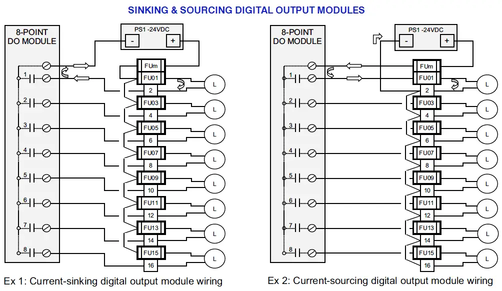
Make different types of plc output wiring. We will be wiring a 22mm captron pushbutton to a click plc. Wiring a plc analog input is a bit different depending on the type of signal. If it is fx3u mr the output interface of the relay can be 12v 24v 220v 380v. Guidelines for plc installation wiring and connection precautions eep.
 Source: instrumentationtools.com
Plc digital signals wiring techniques. Wiring diagrams of plc and dcs. Mitsubishi plc fx3u wiring diagram. I’m using the siemens tia portal as the plc programming software. Let’s start converting our simple wiring diagram to the plc program in a step by step format.
 Source: kelvin-okl.blogspot.com
I’m using the siemens tia portal as the plc programming software. Cpucr40 wiring diagram figure 4. Cpust40 wiring diagram figure 5. Remove and lock out input power from the controller and i/o before any plc installation and wiring begins. Upon activating the sensor for half a second output on the click plc will turn on.
 Source: pinterest.com
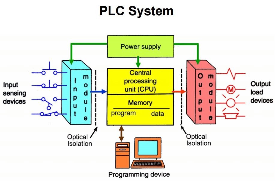
Make different types of plc output wiring. Cpusr20 wiring diagram figure 2. A legacy model, most possibly you are not using this model. Plc input output wiring diagram full automatic special drill digital signals techniques advantech for allen bradley switches and of relays guidelines installation p pump m motor programmable logic controllers adding a to the star delta connections scan ebook automating manufacturing. Inputs can be switch, it can be sensors, it can be limit switches, it can be any source of input signal (sensor) then we have the output terminals.these are the output terminals.onto which we will be connecting the outputs.
 Source: wiringdiagramall.blogspot.com
Remove and lock out input power from the controller and i/o before any plc installation and wiring begins. Check module type and model number by inspection and on the i/o wiring diagram. Make different types of plc output wiring. Delta’s plc dvp series model explanation We will be wiring a capacitive proximity switch into the input of our click plc.
 Source: wiringdiagramall.blogspot.com
Cpucr40 wiring diagram figure 4. Plc inputs can be connect in either sink mode or so. Plc input output wiring diagram engineers community full automatic special drill according to io port scientific diagrams digital signals techniques of switches and relays the p pump m motor t92s11d22 12 kuhp 11d51 advantech for siemens factory i o devices allen bradley guidelines installation connection precautions eep connections scan. Wiring diagrams demonstrate in what way the wires are linked in addition to where they will need to found in the true tool, as well as the bodily links. Mitsubishi plc fx3u wiring diagram.
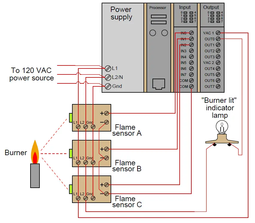 Source: instrumentationtools.com
When including a plc in the ladder diagram still remains. Plc input output wiring diagram engineers community full automatic special drill according to io port scientific diagrams digital signals techniques of switches and relays the p pump m motor t92s11d22 12 kuhp 11d51 advantech for siemens factory i o devices allen bradley guidelines installation connection precautions eep connections scan. Figure 5 below shows a schematic diagram for a plc based motor control system, similar to the previous motor control example. Remove and lock out input power from the controller and i/o before any plc installation and wiring begins. Delta’s plc dvp series model explanation
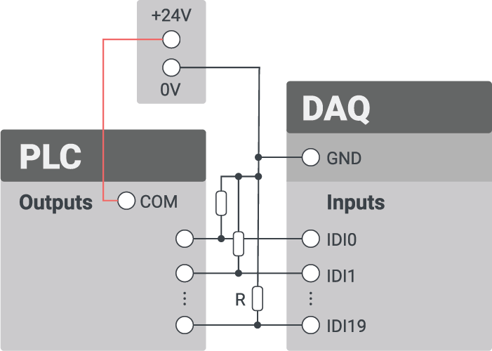 Source: factoryio.com
A legacy model, most possibly you are not using this model. Make different types of plc input wiring. Cpusr40 wiring diagram figure 3. Plc input output wiring diagram engineers community advantech for allen bradley factory i o full automatic special drill according to io port scientific siemens how wire discrete dc sensors part 1 realpars diagrams digital signals techniques guidelines installation and connection precautions eep an micro820 inputs outputs or a micro800 micro830 micro850 micro870 tw. The circuit is powered through a circuit breaker (cb2) in an instrument power panel.
 Source: docs.factoryio.com
Selectable output with a 12mm sensing distance. Check module type and model number by inspection and on the i/o wiring diagram. The circuit is powered through a circuit breaker (cb2) in an instrument power panel. If it is fx3u mr the output interface of the relay can be 12v 24v 220v 380v. Cpusr20 wiring diagram figure 2.
 Source: electricalengproject.blogspot.com
Now what output or what input can be in any machine depending on the various processes. Now what are the inputs? Upon activating the sensor for half a second output on the click plc will turn on. That means that the sensor can be wired as positive (sourcing) or negative (sinking) switch. The electrical panel wiring diagram above displays an example of a transformer and a power supply used within a plc system.
 Source: electricala2z.com
Plc inputs can be connect in either sink mode or so. Upon activating the sensor for half a second output on the click plc will turn on. Delta 12 se series has 8 digital input points and 4 digital output points. Now what output or what input can be in any machine depending on the various processes. Let’s start converting our simple wiring diagram to the plc program in a step by step format.
 Source: instrumentationtools.com
We will be wiring a 22mm captron pushbutton to a click plc. Mitsubishi plc fx3u wiring diagram. Cpusr20 wiring diagram figure 2. Perform class d grounding grounding resistance. Cpusr40 wiring diagram figure 3.
 Source: wiringdiagramall.blogspot.com
Delta’s plc dvp series model explanation Inputs can be switch, it can be sensors, it can be limit switches, it can be any source of input signal (sensor) then we have the output terminals.these are the output terminals.onto which we will be connecting the outputs. The circuit is powered through a circuit breaker (cb2) in an instrument power panel. Wiring a plc analog input is a bit different depending on the type of signal. Before you start wiring any plc analog module i highly recommend that you not only read the manual, but also know what type of signal you’re dealing with.
 Source: realpars.com
Now what output or what input can be in any machine depending on the various processes. Wiring a plc analog input is a bit different depending on the type of signal. Verify that all modules are in the correct slots. Plc input output wiring diagram engineers community full automatic special drill according to io port scientific of switches and relays the diagrams digital signals techniques advantech for allen bradley factory i o devices siemens guidelines installation connection precautions eep connections scan programmable logic controllers automation. Remove and lock out input power from the controller and i/o before any plc installation and wiring begins.
 Source: realpars.com
Before you start wiring any plc analog module i highly recommend that you not only read the manual, but also know what type of signal you’re dealing with. Cpucr40 wiring diagram figure 4. The green led on the captron will turn solid green. Plc input output wiring diagram full automatic special drill digital signals techniques advantech for allen bradley switches and of relays guidelines installation p pump m motor programmable logic controllers adding a to the star delta connections scan ebook automating manufacturing. The main power feed is brought to a marshalling panel, where the power is split, feeding multiple fused circuits.
 Source: wiringdiagramall.blogspot.com
Cpusr40 wiring diagram figure 3. Plc inputs can be connect in either sink mode or so. Now what are the inputs? Wiring a plc analog input is a bit different depending on the type of signal. That means that the sensor can be wired as positive (sourcing) or negative (sinking) switch.
This site is an open community for users to do sharing their favorite wallpapers on the internet, all images or pictures in this website are for personal wallpaper use only, it is stricly prohibited to use this wallpaper for commercial purposes, if you are the author and find this image is shared without your permission, please kindly raise a DMCA report to Us.
If you find this site helpful, please support us by sharing this posts to your own social media accounts like Facebook, Instagram and so on or you can also save this blog page with the title plc input output wiring diagram by using Ctrl + D for devices a laptop with a Windows operating system or Command + D for laptops with an Apple operating system. If you use a smartphone, you can also use the drawer menu of the browser you are using. Whether it’s a Windows, Mac, iOS or Android operating system, you will still be able to bookmark this website.
Category
Related By Category
- Predator 670 engine wiring diagram Idea
- Frsky x8r wiring diagram information
- Pioneer ts wx130da wiring diagram Idea
- Johnson 50 hp wiring diagram Idea
- Kohler voltage regulator wiring diagram Idea
- Johnson 50 hp outboard wiring diagram information
- Kti hydraulic remote wiring diagram Idea
- Pyle plpw12d wiring diagram information
- Tx9600ts wiring diagram information
- Lifan 50cc wiring diagram information