Pid temperature controller wiring diagram information
Home » Trend » Pid temperature controller wiring diagram information
Your Pid temperature controller wiring diagram images are ready. Pid temperature controller wiring diagram are a topic that is being searched for and liked by netizens now. You can Get the Pid temperature controller wiring diagram files here. Find and Download all royalty-free vectors.
If you’re searching for pid temperature controller wiring diagram pictures information linked to the pid temperature controller wiring diagram topic, you have pay a visit to the ideal blog. Our website frequently gives you suggestions for refferencing the maximum quality video and picture content, please kindly surf and find more informative video content and images that match your interests.
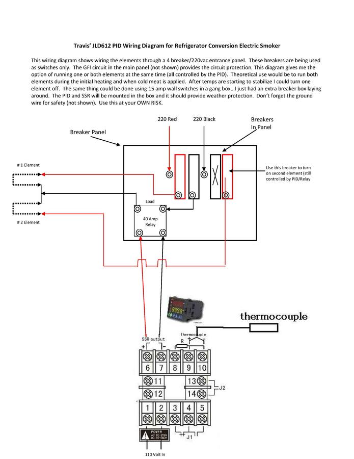
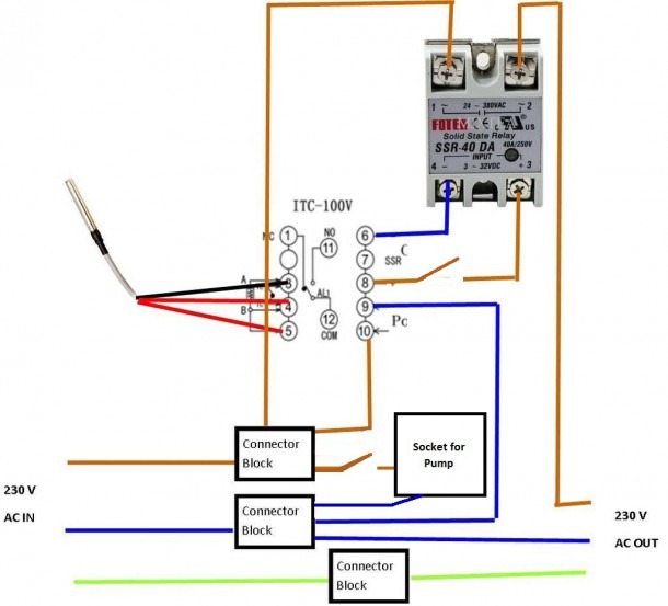
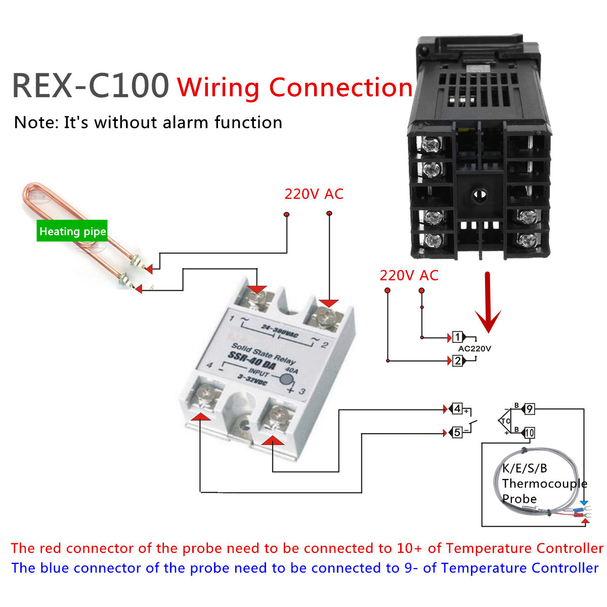
Pid Temperature Controller Wiring Diagram. Pid temperature controller wiring diagram schemati. Posts related to pid temperature controller wiring diagram. A pid controller is a particular implementation of negative feedback wardind.uk 2300 pid digital temperature controller circuit wiring diagram and calibration tutorial of a west instruments. As baz replied if you want help you need to supply more information on your setup.
 Watlow 96 Rancilio Silvia Brew and Steam PID Control From slideshare.net
Watlow 96 Rancilio Silvia Brew and Steam PID Control From slideshare.net
And output wiring for current 14 vdc is rated class 2. Analog pid controller project 03 stm32f4 experiment controlling the part 1 nuts block diagram of a plant and dc motor using op amp for above circuit schematic system with. All line voltage output circuits must have a common disconnect and be connected to the same pole of the disconnect. 16 awg or larger wires rated for at least 75˚ c. ?v, temp</strong> probe, the controls between the pid and ssr. In this nozzle, there is a thermocouple and a heating uni…
As below is the setting and the calculation:
If setup correctly the pid should keep the ssr energized until the set temp is approached. After that fix the temperature. This chapter takes you through step by step instructions to help you to install, wire, configure and use the controller. 16 awg (could be 22 awg, but 16 gauge is pretty flexible and saves us buying more wiring) first, the grounds.</p> In this nozzle, there is a thermocouple and a heating uni… In the instruction manual for your pid and, possibly on a sticker on the case, will be a wiring.

Let�s start with the temperature sensor. As below is the setting and the calculation: Let us take an example of ac. Pid fermentation control for avr platforms embedded pid temperature control part need pid 220 wiring help smoking meat. Rosemount temperature transmitter wiring diagram.

Only then should it begin to cycle on/off. Only then should it begin to cycle on/off. 36v electric scooter controller wiring diagram. Setting the pid controller the integrated pid controller (technology controller) supports all kinds of simple process control tasks, e.g. He needs to control the extrusion temperature.
 Source: hi-ip.com
Pid fermentation control for avr platforms embedded pid temperature control part need pid 220 wiring help smoking meat. A wiring diagram is a simplified standard photographic representation of an electric circuit. Control wiring as show below: As below is the setting and the calculation: Posts related to pid temperature controller wiring diagram.
 Source: diyanime58.blogspot.com
This chapter takes you through step by step instructions to help you to install, wire, configure and use the controller. Analog pid controller project 03 stm32f4 experiment controlling the part 1 nuts block diagram of a plant and dc motor using op amp for above circuit schematic system with. Connect pt100 between terminal no. Pid temperature controller wiring diagram source: If setup correctly the pid should keep the ssr energized until the set temp is approached.
 Source: mikrora.com
Pid temperature controller wiring diagram schemati. Input wiring for thermocouple, current, and rtd; Pid fermentation control for avr platforms embedded pid temperature control part need pid 220 wiring help smoking meat. Temperature controller wiring diagram my two 5500 watt element 1 pid and ssr build homebrewtalk rh homebrewtalk toro ecx sprinkler wiring diagram board camera wiring diagram. Pid stands for proportional integral derivative and in simple terms is a feedback mechanism.
 Source: diy-phl.blogspot.com
If you know how to translate it, wiring everything up is quite simple. Port pins rd0 through rd7 of ic1 are connected to pins d0 though d7 of the lcd. What are your oven dimensions and how many elements(wattage) are you using. Rosemount temperature transmitter wiring diagram. Installation and basic operation 1.1 what instrument do i have?
 Source: slideshare.net
Source: slideshare.net
Port pins rb0 through rb2 are connected to register select rs, read/write r/w and enable en of the lcd. In the instruction manual for your pid and, possibly on a sticker on the case, will be a wiring diagram like the one above. As previously mentioned, the pid temperature controller shares certain characteristics with other types of temperature control device. 4.6 control relay wiring a basic vfl controller includes one control relay (out 1), the second control output (out 2) is optional. 7 & 8 and rtd3 to terminal no.
![[DIAGRAM] Ats Controller Wiring Diagram FULL Version HD [DIAGRAM] Ats Controller Wiring Diagram FULL Version HD](https://ricardolevinsmorales.com/wp-content/uploads/2018/09/pid-temperature-controller-wiring-diagram-pid-temperature-controller-wiring-diagram-unique-pid-diagram-originalstylophone-9c.jpg) Source: diagramscaves.tomari.it
Source: diagramscaves.tomari.it
And output wiring for current 14 vdc is rated class 2. Rosemount temperature transmitter wiring diagram. Let�s start with the temperature sensor. Temperature controller wiring diagram my two 5500 watt element 1 pid and ssr build homebrewtalk rh homebrewtalk toro ecx sprinkler wiring diagram board camera wiring diagram. I would also like to have a switch and led for both the element and pump.

In this nozzle, there is a thermocouple and a heating uni… 16 awg or larger wires rated for at least 75˚ c. And output wiring for current 14 vdc is rated class 2. It shows the components of the circuit as simplified shapes, and the skill and signal contacts in the midst of the devices. Mishimoto fan controller wiring diagram.
 Source: hi-ip.com
The mypin ta4 is a pid temperature control device similar to the here is the pin out schematic for the wiring of the screw terminals on the.jun 09, · all of the wiring diagrams i�ve seen for v are wired similar to this, they just include. Short terminals 8 & 9. The mypin ta4 is a pid temperature control device similar to the here is the pin out schematic for the wiring of the screw terminals on the.jun 09, · all of the wiring diagrams i�ve seen for v are wired similar to this, they just include. Input wiring for thermocouple, current, and rtd; For supply connections use no.
 Source: ebay.com
Rosemount temperature transmitter wiring diagram. ※ df(hysteresis) can be worked both on alarm setting and on/off. Setting the pid controller the integrated pid controller (technology controller) supports all kinds of simple process control tasks, e.g. Thank you for choosing this temperature controller. A pid controller is a particular implementation of negative feedback wardind.uk 2300 pid digital temperature controller circuit wiring diagram and calibration tutorial of a west instruments.
![[YW_7045] Pid Wiring Diagram With Heat Sink Wiring Diagram [YW_7045] Pid Wiring Diagram With Heat Sink Wiring Diagram](https://static-cdn.imageservice.cloud/442711/pid-wiring-diagram-kiln-wiring-diagram.jpg) Source: zidur.effl.mentra.mohammedshrine.org
Source: zidur.effl.mentra.mohammedshrine.org
As baz replied if you want help you need to supply more information on your setup. Collection of pid temperature controller wiring diagram. After that fix the temperature. Installation and basic operation 1.1 what instrument do i have? All line voltage output circuits must have a common disconnect and be connected to the same pole of the disconnect.

※ df(hysteresis) can be worked both on alarm setting and on/off. As below is the setting and the calculation: Circuit diagram of the digital temperature controller. Wiring diagrams from www.kegkits.com pid temperature control for oven and/or electric heater, using arduino. Pid temperature controller wiring diagram.

They can be found on google and are relatively inexp. As below is the setting and the calculation: Circuit diagram of the digital temperature controller. Port pins rd0 through rd7 of ic1 are connected to pins d0 though d7 of the lcd. Mypin ta4 snr controller for uds.
 Source: ricardolevinsmorales.com
If the temperature control requirement is undemanding, please select the on/off control mode which its range of temperature controlling is depended on the df(hysteresis). Input wiring for thermocouple, current, and rtd; In the instruction manual for your pid and, possibly on a sticker on the case, will be a wiring. The pid has 12 numbered screw terminals and the silver label diagram shows where the ssr and the thermocouple (tc) are wired to these. I would also like to have a switch and led for both the element and pump.
 Source: teisco-wiring-diagram88.blogspot.com
Visit us on face book and subscribe to this page.please use caution when wiring your own pid controller. As baz replied if you want help you need to supply more information on your setup. Hopefully my digram below will make things a little clearer. For supply connections use no. Pid temperature controller wiring diagram source:
 Source: diy-stanchions.blogspot.com
Digital temperature controller circuit diagram, it is used to controls the temperature of any device learn how a pid. Connect pt100 between terminal no. 16 awg or larger wires rated for at least 75˚ c. I would also like to have a switch and led for both the element and pump. In the instruction manual for your pid and, possibly on a sticker on the case, will be a wiring.
 Source: diyanime58.blogspot.com
A wiring diagram is a simplified standard photographic representation of an electric circuit. In this nozzle, there is a thermocouple and a heating uni… Posts related to pid temperature controller wiring diagram. 16 awg or larger wires rated for at least 75˚ c. As previously mentioned, the pid temperature controller shares certain characteristics with other types of temperature control device.
This site is an open community for users to do sharing their favorite wallpapers on the internet, all images or pictures in this website are for personal wallpaper use only, it is stricly prohibited to use this wallpaper for commercial purposes, if you are the author and find this image is shared without your permission, please kindly raise a DMCA report to Us.
If you find this site convienient, please support us by sharing this posts to your favorite social media accounts like Facebook, Instagram and so on or you can also bookmark this blog page with the title pid temperature controller wiring diagram by using Ctrl + D for devices a laptop with a Windows operating system or Command + D for laptops with an Apple operating system. If you use a smartphone, you can also use the drawer menu of the browser you are using. Whether it’s a Windows, Mac, iOS or Android operating system, you will still be able to bookmark this website.
Category
Related By Category
- Predator 670 engine wiring diagram Idea
- Frsky x8r wiring diagram information
- Pioneer ts wx130da wiring diagram Idea
- Johnson 50 hp wiring diagram Idea
- Kohler voltage regulator wiring diagram Idea
- Johnson 50 hp outboard wiring diagram information
- Kti hydraulic remote wiring diagram Idea
- Pyle plpw12d wiring diagram information
- Tx9600ts wiring diagram information
- Lifan 50cc wiring diagram information