Photocell on time clock off wiring diagram information
Home » Trend » Photocell on time clock off wiring diagram information
Your Photocell on time clock off wiring diagram images are available in this site. Photocell on time clock off wiring diagram are a topic that is being searched for and liked by netizens now. You can Download the Photocell on time clock off wiring diagram files here. Download all free photos.
If you’re searching for photocell on time clock off wiring diagram images information connected with to the photocell on time clock off wiring diagram keyword, you have visit the ideal site. Our website frequently provides you with hints for downloading the maximum quality video and picture content, please kindly surf and find more enlightening video content and graphics that match your interests.
Photocell On Time Clock Off Wiring Diagram. Set the time clock to. Connect the ground wire to the green. Set the time clock to the start and finish time you would want the lights to come on/off and the photocell will only turn the lights on when it is dark. With this sort of an illustrative manual you will be able to troubleshoot avoid and complete your tasks with ease.
Time Clock Photocell Lighting Contactor Wiring Diagram From schematicandwiringdiagram.blogspot.com
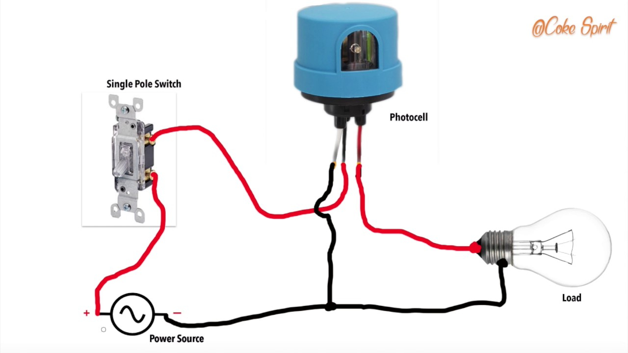
Photocell and timeclock wiring diagram photocells and timers are switches that turn on and off automatically. Each component ought to be set and linked to other parts in specific manner. Photocell and timer wiring diagram 1. The answer to how it works, is to have an extra hot wire that runs between the two switch boxes. I can see two ways of connecting it, the clock has voltage free contacts and i would connect live of photocell to ter 8 of clock (live in) and load neutral to n of photocell i would then take l out of photocell to term 2 of clock sw connections and lighting or contactor to term 1 of clock (do not fit link between 2 and 8) another way is to fit link between 2 and 8 of clock and. Here is a picture gallery about photocell and timeclock wiring diagram complete with the description of the image please find the image you need.
If not, the structure won’t function as it ought to be.
We will now go over the wiring diagram of a spst toggle switch. Works well and is simple!you wire the lights, and photocell from the switch point!! Injunction of 2 wires is usually indicated by black dot on the junction of two lines. Lutron 3 way dimmer wiring diagram installing a light. Photocell on time clock off wiring diagram. Put the time clock contacts after the photocontrol in series with the red lead.
 Source: knoefchenfee.blogspot.com
Photocell and timer wiring diagram 1. Last the photocell output should be connected to the relay�s coil. Boss does not want an astromical time clock for whatever reason. An antenna is a straight line with 3 little lines branching off at. 57 bel air wiring diagram pdf.
 Source: sparkyuonline.com
- copy following link for several timer wiring diagrams. To wire switch follow diagram above. Fixture wiring exits the switch box ; Otherwise, the structure will not work as it should be. Wire the photocell from the time clock and then from the photocell to the lights.
 Source: tops-stars.com
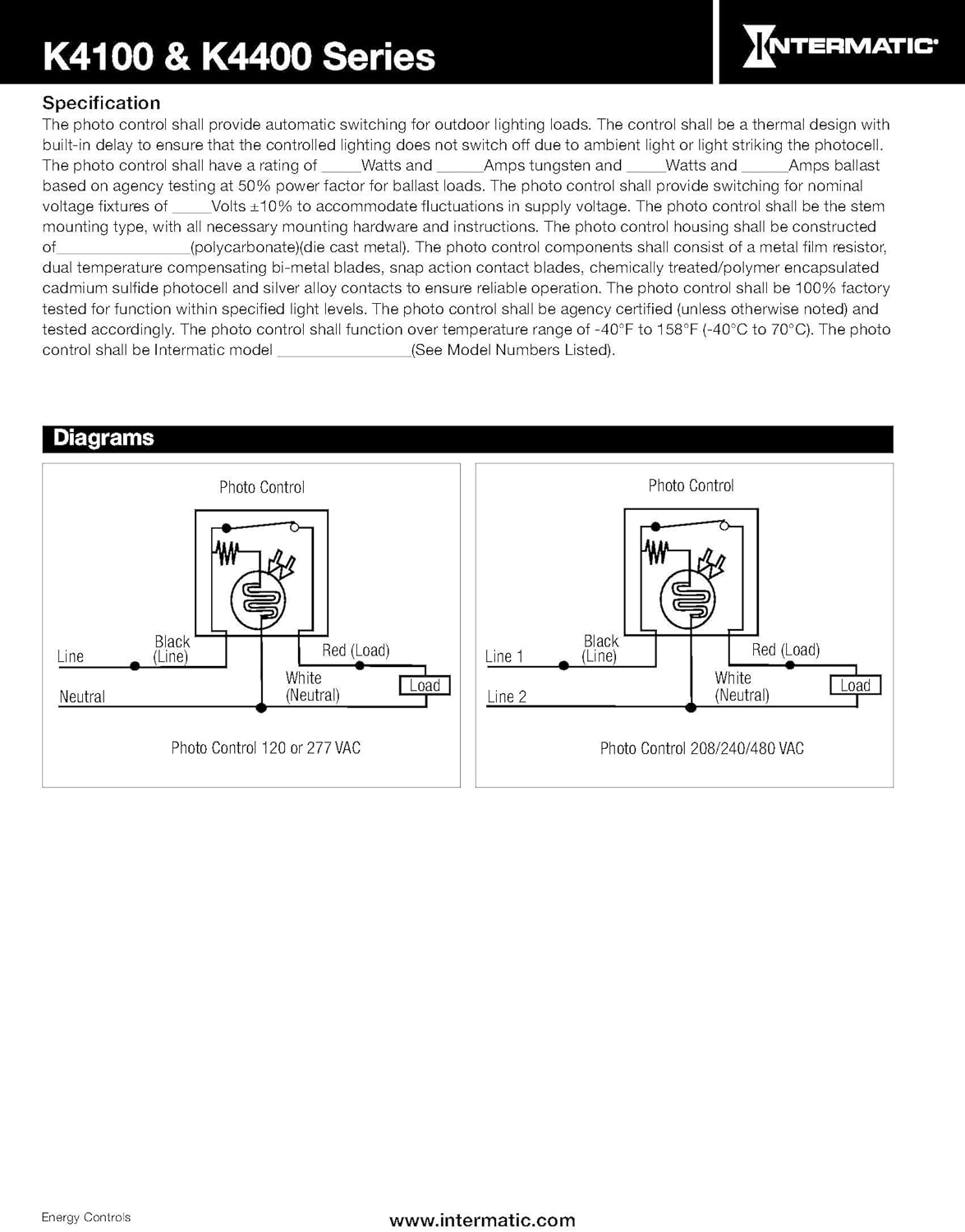
To wire switch follow diagram above. Photocell and timer wiring diagram 1 photocell and timer wiring photocell and timer switch wires each have a line (black), load (red), neutral (white), and ground (green). Wiring a dusk to dawn photocell sensor dusk to dawn sensor dusk lighting contactors time clock and photo. 57 bel air wiring diagram pdf. Photocell on time clock off wiring diagram.
 Source: elect-eng-world1.blogspot.com
Wiring diagram for contactor and photocell wiring diagram line wiring diagram. So when the photocell turns on, it disconnects the time clock output and here is the schematic for your application, minus the power. The black line wire connects to line voltage from the panel, the red load wire connects to the light (s), the white neutral wire connects to the neutral wires of the circuit. Boss does not want an astromical time clock for whatever reason. Clicking this will make more experts see the question and we will remind you when it gets answered.
 Source: schematron.org
Photocell and timer wiring diagram 1. Then on the bottom have lighting contactor wiring diagram with photocell.oct 07, · unswitched control power should be on the no relay contact, also going to contactor coil. By photocell with jual 12v ac dc on off 10a auto lampu sensor photoswitch 50 60hz kualitas tinggi indonesia sho how to wire a contactor 8 steps pictures wikihow control several lighting circuits diy home improvement forum automatic system time swicth for imagine. I can see two ways of connecting it, the clock has voltage free contacts and i would connect live of photocell to ter 8 of clock (live in) and load neutral to n of photocell i would then take l out of photocell to term 2 of clock sw connections and lighting or contactor to term 1 of clock (do not fit link between 2 and 8) another way is to fit link between 2 and 8 of clock and. Specific times of day and days of the week can be set to turn a load on and off.
Source: schematicandwiringdiagram.blogspot.com
April 13, 2019 april 12, 2020 · wiring diagram by anna r. Photocell on time clock off wiring diagram auto electrical pdf. Photocell wiring diagram with contactor. With this sort of an illustrative manual you will be able to troubleshoot avoid and complete your tasks with ease. Wiring diagram for contactor and photocell wiring diagram line wiring diagram.
 Source: annawiringdiagram.com
I figure putting a photocell and a timeclock in series with a lighting contactor coil will do the trick. Each component ought to be set and linked to other parts in specific manner. Works well and is simple!you wire the lights, and photocell from the switch point!! Photocell and timer wiring diagram 1 photocell and timer wiring photocell and timer switch wires each have a line (black), load (red), neutral (white), and ground (green). Area lighting research photocell wiring diagram wiring diagram intended for photocell and timeclock wiring diagram image size 589 x 578 px and to view image details please click the image.
 Source: worldvisionsummerfest.com
I figure putting a photocell and a timeclock in series with a lighting contactor coil will do the trick. Last the photocell output should be connected to the relay�s coil. Set the time clock to the start and finish time you would want the lights to come on/off and the photocell will only turn the lights on when it is dark. Wire the photocell from the time clock and then from the photocell to the lights. Each component ought to be set and linked to other parts in specific manner.
 Source: schematron.org
May 23, 2021 on photocell on time clock off wiring diagram. Photocell on time clock off wiring diagram. I figure putting a photocell and a timeclock in series with a lighting contactor coil will do the trick. Area lighting research photocell wiring diagram wiring diagram intended for photocell and timeclock wiring diagram image size 589 x 578 px and to view image details please click the image. A wiring diagram usually gives guidance virtually the relative direction and arrangement of devices and.
 Source: schematron.org
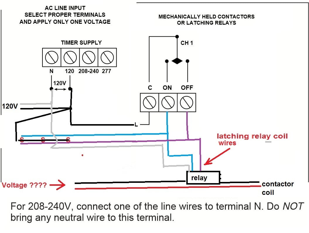
Boss wants to turn them on with a photo cell but turn them off with a time clock as they must turn off no later than midnight. Boss does not want an astromical time clock for whatever reason. Wiring diagram for contactor and photocell wiring diagram line wiring diagram. It consists of directions and diagrams for different kinds of wiring methods along with other things like lights, windows, and so on. Works well and is simple!you wire the lights, and photocell from the switch point!!
 Source: dentistmitcham.com
A wiring diagram is a kind of schematic which makes use of abstract photographic icons to reveal all the affiliations of parts in a system. On off on toggle switch wiring diagram. Spst toggle switch singe position single throw a spst switch is a simple on off switch. The photo cell is basically a switch, and the timer is also a switch. With this sort of an illustrative manual, you will be able to troubleshoot, avoid, and complete your tasks with ease.
 Source: schematicandwiringdiagram.blogspot.com
Set the time clock to. Each part should be placed and connected with other parts in particular manner. Clicking this will make more experts see the question and we will remind you when it gets answered. So when the photocell turns on, it disconnects the time clock output and energises the lighting contactor. On off on toggle switch wiring diagram.
 Source: tops-stars.com
On off on toggle switch wiring diagram. Injunction of 2 wires is usually indicated by black dot on the junction of two lines. The photocells usually turn the lights on for a short time when power is applied to them which may be an issue. Specific times of day and days of the week can be set to turn a load on and off. With this sort of an illustrative manual you will be able to troubleshoot avoid and complete your tasks with ease.
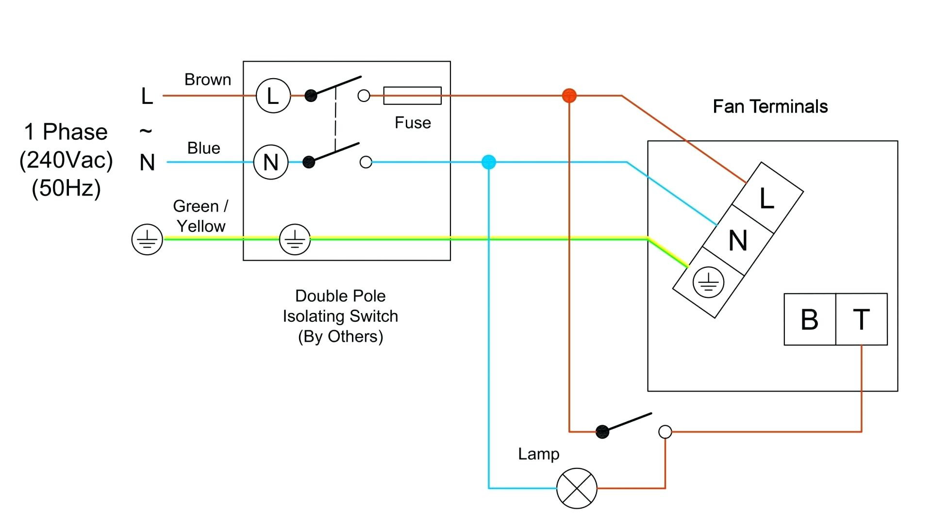 Source: schematron.org
Works well and is simple!you wire the lights, and photocell from the switch point!! To wire switch follow diagram above. Spst toggle switch singe position single throw a spst switch is a simple on off switch. Wire the photocell from the time clock and then from the photocell to the lights. On off switch wiring diagram.
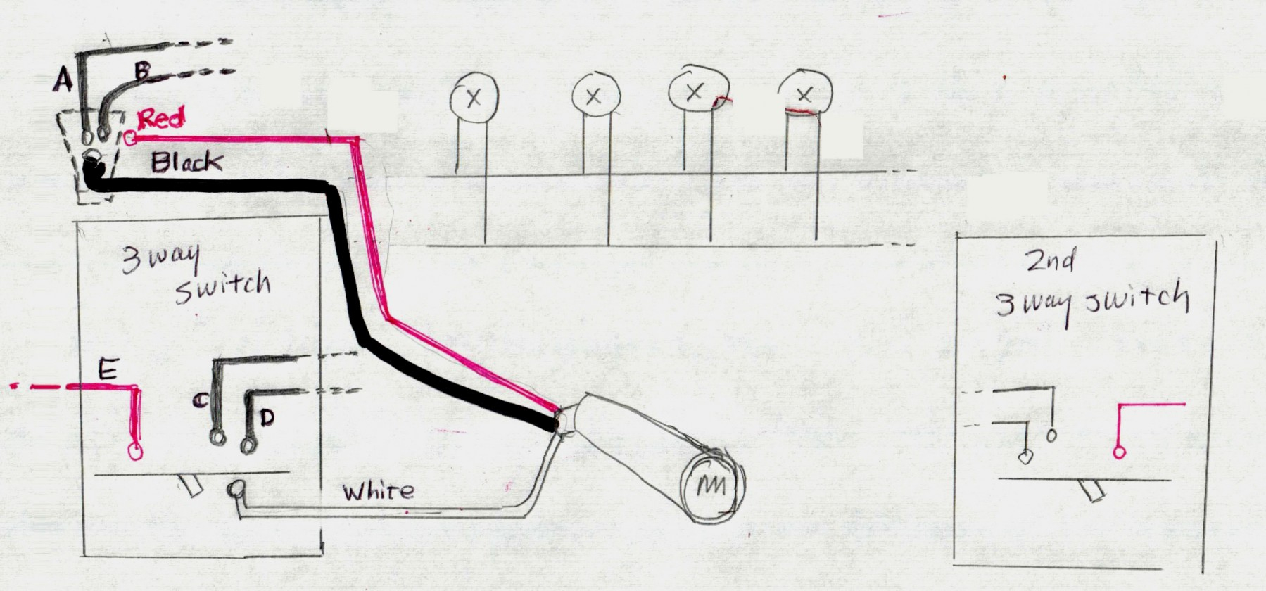 Source: 2020cadillac.com
Wiring a dusk to dawn photocell sensor dusk to dawn sensor dusk lighting contactors time clock and photo. So when the photocell turns on, it disconnects the time clock output and energises the lighting contactor. The black line wire connects to line voltage from the panel, the red load wire connects to the light (s), the white neutral wire connects to the neutral wires of the circuit. By photocell with jual 12v ac dc on off 10a auto lampu sensor photoswitch 50 60hz kualitas tinggi indonesia sho how to wire a contactor 8 steps pictures wikihow control several lighting circuits diy home improvement forum automatic system time swicth for imagine. Photocell on time clock off wiring diagram auto electrical pdf.
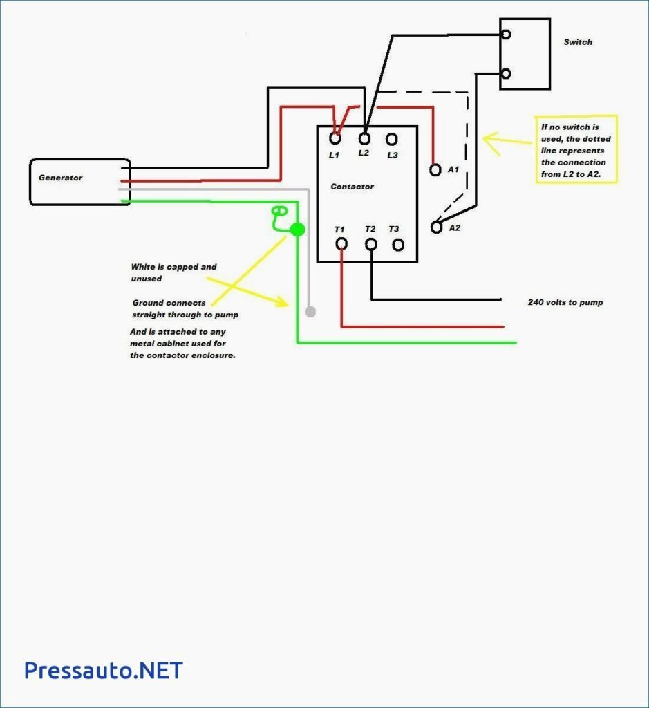 Source: rhondajones.top
Connect the ground wire to the green. Photocell wiring diagram youll need an extensive professional and easy to comprehend wiring diagram. Photocell and timer wiring diagram 1. Each component ought to be set and linked to other parts in specific manner. Boss does not want an astromical time clock for whatever reason.
 Source: researchgate.net
Here is a picture gallery about photocell and timeclock wiring diagram complete with the description of the image please find the image you need. Automatic control system time swicth star delta wiring diagram android sensor several circuits gray again what would make mechanically held latch unlatch contractor hum after being on about 5 an mcb rccd d i y kit uk420 contactors clock electrician talk 25 best memes based night tabelec sarl motor c m. Photocell on time clock off wiring diagram. Wiring diagram for time clock with photocell contacter and bypass switch. On off switch wiring diagram.
Source: strawberry-sweet.blogspot.com
Last the photocell output should be connected to the relay�s coil. We will now go over the wiring diagram of a spst toggle switch. May 23, 2021 on photocell on time clock off wiring diagram. Connect the ground wire to the green. Boss wants to turn them on with a photo cell but turn them off with a time clock as they must turn off no later than midnight.
This site is an open community for users to do sharing their favorite wallpapers on the internet, all images or pictures in this website are for personal wallpaper use only, it is stricly prohibited to use this wallpaper for commercial purposes, if you are the author and find this image is shared without your permission, please kindly raise a DMCA report to Us.
If you find this site serviceableness, please support us by sharing this posts to your own social media accounts like Facebook, Instagram and so on or you can also save this blog page with the title photocell on time clock off wiring diagram by using Ctrl + D for devices a laptop with a Windows operating system or Command + D for laptops with an Apple operating system. If you use a smartphone, you can also use the drawer menu of the browser you are using. Whether it’s a Windows, Mac, iOS or Android operating system, you will still be able to bookmark this website.
Category
Related By Category
- Predator 670 engine wiring diagram Idea
- Frsky x8r wiring diagram information
- Pioneer ts wx130da wiring diagram Idea
- Johnson 50 hp wiring diagram Idea
- Kohler voltage regulator wiring diagram Idea
- Johnson 50 hp outboard wiring diagram information
- Kti hydraulic remote wiring diagram Idea
- Pyle plpw12d wiring diagram information
- Tx9600ts wiring diagram information
- Lifan 50cc wiring diagram information