Phase dimming wiring diagram information
Home » Trending » Phase dimming wiring diagram information
Your Phase dimming wiring diagram images are ready. Phase dimming wiring diagram are a topic that is being searched for and liked by netizens today. You can Get the Phase dimming wiring diagram files here. Download all free images.
If you’re looking for phase dimming wiring diagram pictures information related to the phase dimming wiring diagram keyword, you have pay a visit to the right blog. Our site always provides you with suggestions for downloading the maximum quality video and image content, please kindly surf and find more informative video articles and images that fit your interests.
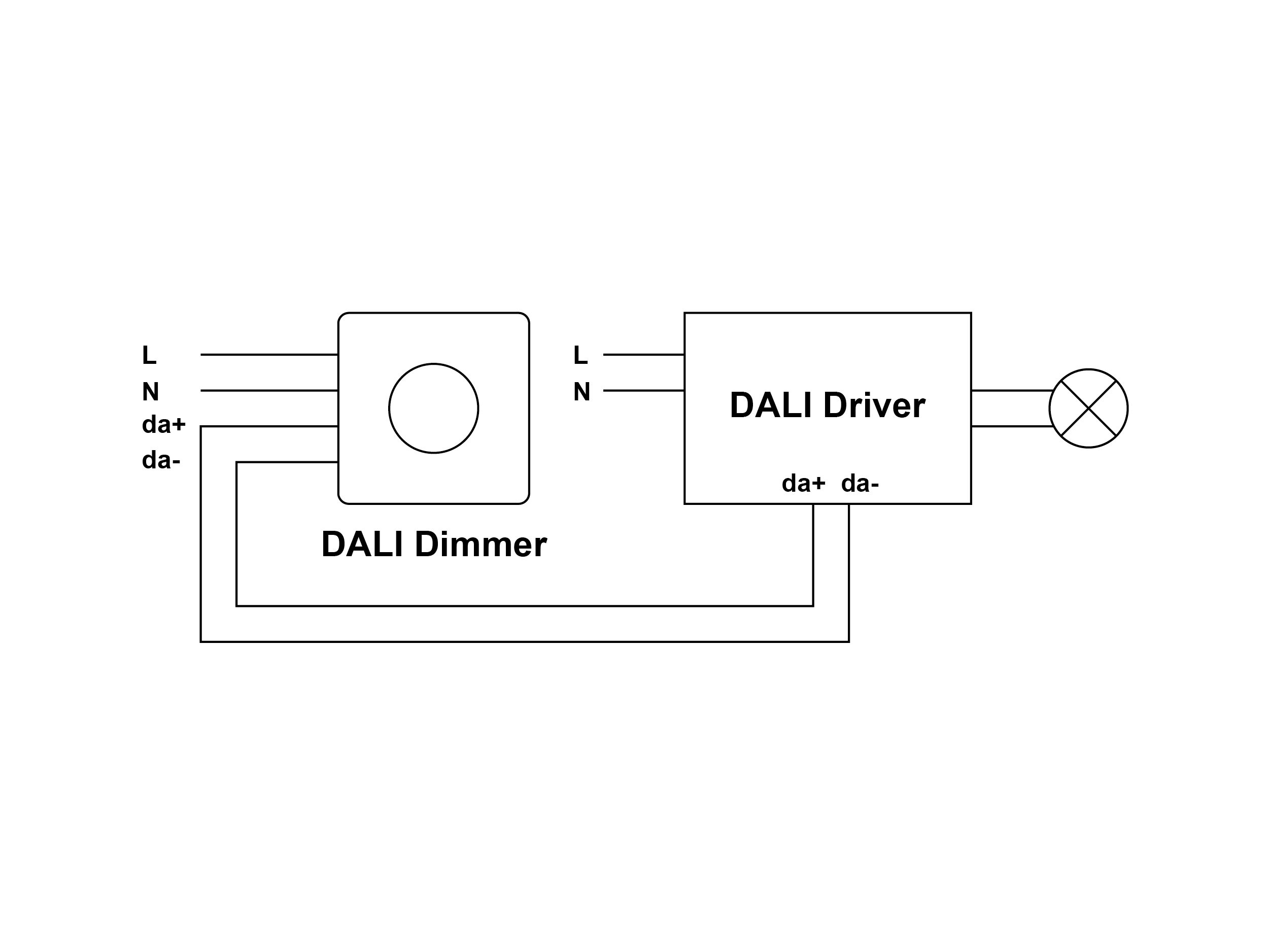
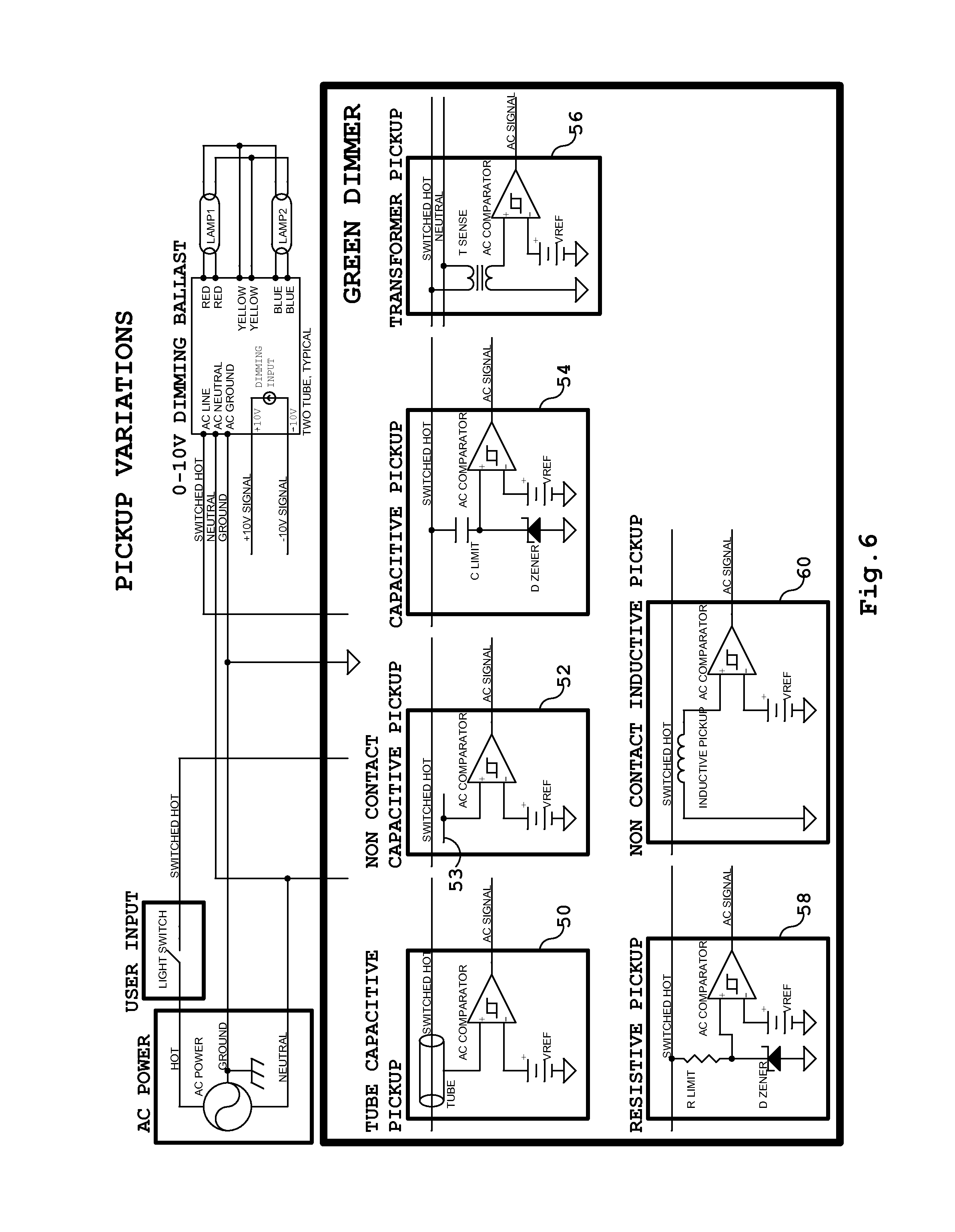
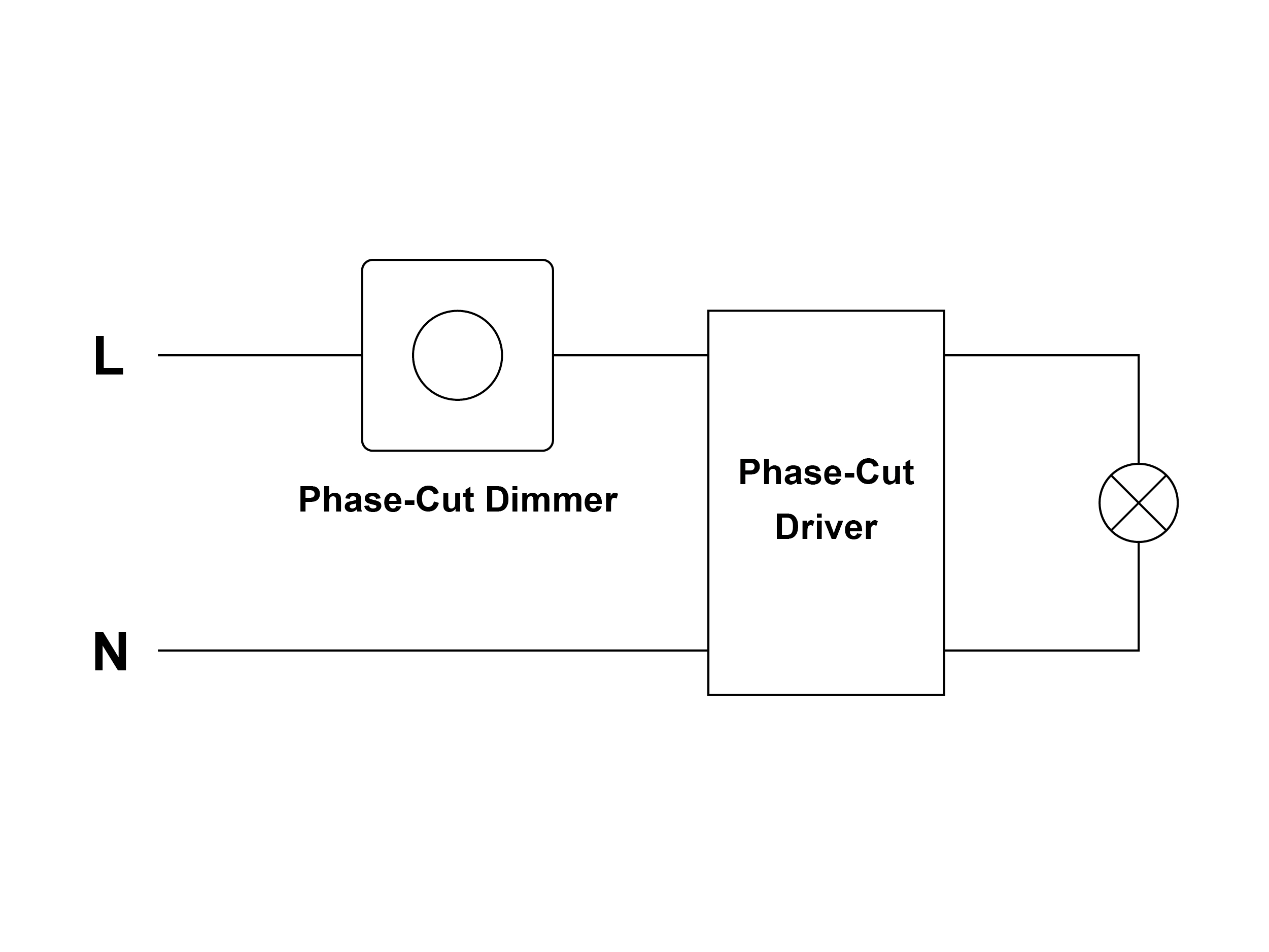
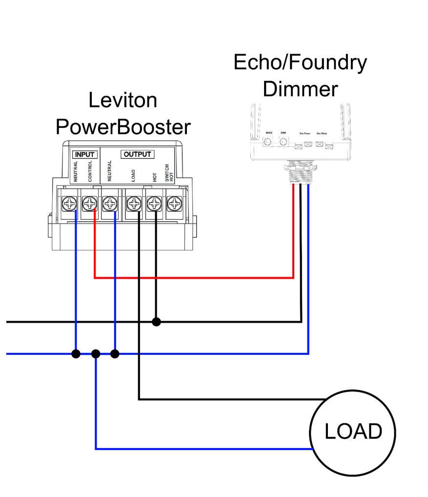
Phase Dimming Wiring Diagram. Usai lighting reverse phase dimming solutions. The design, reverse phase dimmers generally require a neutral wire for operation. Image result for split air conditioner wiring diagram electrical wiring diagram refrigeration and air conditioning air conditioning system. 3 phase power electrical diagram.
 Low Voltage Led Dimmer Wiring Diagram Wiring Diagram Schemas From wiringschemas.blogspot.com
A wiring diagram is a streamlined standard pictorial representation of an electrical circuit. Leading edge phase control (le) dimming wiring diagram le phase control dimmer switch dimmed hot (black typical) electrical panel hot (black typical) 120v neutral (white) ground ground led pendant, sconce, or ceiling lutron 253p or equal (1) pendant per switch up to (8) ceiling mounts per switch or other lutron compatible controls refer to manufacturer for additional. Find your wiring diagrams walk in freezer here for wiring diagrams walk in freezer and you can print out. 3 phase walk in freezer wiring diagram. Wiring diagram a 3 phase isolator with a stop button; By iot | november 24, 2021.
Lutron diva c l dimmer for dimmable led halogen and incandescent bulbs single pole or 3 way dvcl 153p wh white user manual.
Lutron dimmer wiring surprise the garage journal. Subject to change without notice. Wiring diagrams — common lightcloud wiring applications 12 phase dimming dim phase</strong> loads using a phase dimming adapter. Three line diagram of the electric distribution system being stud scientific phase circuit star and delta electrical4u power configurations with 3ph lines simplified single connection schematics electrical measurement on a motor ac control circuits worksheet network wiring. Three phase electrical wiring installation in a multi story building electrical wiring electrical panel wiring electrical wiring colours. Hot neutral black yellow electronic low voltage 120v dimmer 60hz manufacturer style model
 Source: cars-trucks24.blogspot.com
Wiring diagram single loop smart lighting control panel, replace traditional dimming knob, can be applied to small space of lighting control. Power consumption 450mw load types and ratings supported load types incandescent, halogen, magnetic (iron core, inductive) low voltage (mlv) transformers, forward phase dimmable fluorescents, compact fluorescents, and leds. At the dimmer the black wire is connected to the common wire and at the other end to the hot terminal on the light. All usai elv dimming options are for use with 120v only. Erp offers dimmers with all three dimming options but we do not recommend using more than one dimmer at the same time.
Source: soapscentsations.blogspot.com
Lutron diva c l dimmer for dimmable led halogen and incandescent bulbs single pole or 3 way dvcl 153p wh white user manual. Lutron technical support wiring tool diagrams 368 4493. Wiring diagrams — common lightcloud wiring applications 12 phase dimming dim phase</strong> loads using a phase dimming adapter. A ceiling fan adds function and beauty to a space. This diagram is the same as the previous one but the dimmer comes first in the circuit.
 Source: diyonline68.blogspot.com
Leds are measured in lumens not watts. You can often rely on wiring diagram being an crucial reference that may assist you to preserve time and money. Maximum load 1 gang 2 gang 3+ gang Lutron technical support wiring tool diagrams 368 4493. Lutron c 103p wh centurion 1000w incandescent halogen 3 way preset dimmer in white.
 Source: wiringdiagram.2bitboer.com
They are drawn with the hot on the left and the neutral on the right. For loads under 450w @ 120v and 1000w @ 277v, we recommend the ecosense ecospec adapter. Philips evokit led 2x4 and 2x2 the philips evokit is designed for installation in a wide variety of 2x4 and 2x2 indoor fluorescent based fixtures in horizontal applications. By iot | november 24, 2021. Evokit step dim wiring diagram line 1 s2 line s1 step dim 16aregulations and electrical codes.
 Source: kaoyi.com
Philips evokit led 2x4 and 2x2 the philips evokit is designed for installation in a wide variety of 2x4 and 2x2 indoor fluorescent based fixtures in horizontal applications. Erp offers dimmers with all three dimming options but we do not recommend using more than one dimmer at the same time. Wiring diagrams line neutral load 1 h2 pd pd iri power dimmer dim load 2 switch 2 h1 dim switch 1 line us reaker reaker upto 1920w upto 1920w to reaker panel neutral us the load should be run through relay in the lighting control panel to turn off. For loads under 450w @ 120v and 1000w @ 277v, we recommend the ecosense ecospec adapter. Three phase electrical wiring installation in a multi story building electrical wiring electrical panel wiring electrical wiring colours.
Source: wiringschemas.blogspot.com
Light switch with dimmer home 150w triac 125v wall china led made in com. 3 phase walk in freezer wiring diagram. At the dimmer the black wire is connected to the common wire and at the other end to the hot terminal on the light. Dimmer led driver hot/line black common/neutral white white black triac dimming wiring diagram line voltage 120v 120v output led load low voltage dc wiring diagram powered by ltf ® l.t.f, l.l.c. Erp offers dimmers with all three dimming options but we do not recommend using more than one dimmer at the same time.
 Source: diyonline68.blogspot.com
Watt troffer with 75, life hours. Subject to change without notice. The design, reverse phase dimmers generally require a neutral wire for operation. This diagram is the same as the previous one but the dimmer comes first in the circuit. Three phase electrical wiring installation in a multi story building electrical wiring electrical panel wiring electrical wiring colours.
 Source: ledcontroller.hk
Light switch with dimmer home 150w triac 125v wall china led made in com. (see next page for a more comprehensive list): Reakers should be on the same phase. A wiring diagram is a streamlined standard pictorial representation of an electrical circuit. They are drawn with the hot on the left and the neutral on the right.
 Source: kaoyi.com
Check fuses f1 and f2. A typical reverse phase wiring diagram is shown below: This can result in having to pull additional wire on remodel projects. Leds are measured in lumens not watts. Wiring diagram single loop smart lighting control panel, replace traditional dimming knob, can be applied to small space of lighting control.
 Source: support.etcconnect.com
Also the wiring diagram i have shows a 15 amp fused disc. Leds are measured in lumens not watts. Replacing a maestro dimmer with c l. Control4 home automation wiring diagram. Philips evokit led 2x4 and 2x2 the philips evokit is designed for installation in a wide variety of 2x4 and 2x2 indoor fluorescent based fixtures in horizontal applications.
 Source: diyonline68.blogspot.com
Incandescent/halogen led cfl mlv fluorescent Control4 home automation wiring diagram. For loads under 450w @ 120v and 1000w @ 277v, we recommend the ecosense ecospec adapter. Reakers should be on the same phase. Replacing a maestro dimmer with c l.
 Source: kovodym.blogspot.com
A ceiling fan adds function and beauty to a space. Leds are measured in lumens not watts. Dual voltage single rotation split phase motor dual voltage reversible rotation capacitor motor single phase wiring. Dimmer led driver hot/line black common/neutral white white black triac dimming wiring diagram line voltage 120v 120v output led load low voltage dc wiring diagram powered by ltf ® l.t.f, l.l.c. Replacing a maestro dimmer with c l.
 Source: tops-stars.com
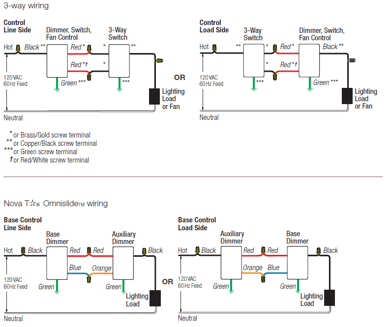
Usai lighting reverse phase dimming solutions. A typical reverse phase wiring diagram is shown below: 3 way dimmer wiring diagrams for lighting control and energy savings. You can often rely on wiring diagram being an crucial reference that may assist you to preserve time and money. Maximum load 1 gang 2 gang 3+ gang
 Source: wiringschemas.blogspot.com
Dimmer led driver hot/line black common/neutral white white black triac dimming wiring diagram line voltage 120v 120v output led load low voltage dc wiring diagram powered by ltf ® l.t.f, l.l.c. The design, reverse phase dimmers generally require a neutral wire for operation. Image result for split air conditioner wiring diagram electrical wiring diagram refrigeration and air conditioning air conditioning system. Control4 home automation wiring diagram. Dimmer led driver hot/line black common/neutral white yellow white black reverse phase elv wiring diagram line voltage 120v 120v output led load low voltage dc powered by ltf ® l.t.f, l.l.c.
 Source: faceitsalon.com
Lutron c 103p wh centurion 1000w incandescent halogen 3 way preset dimmer in white. Wiring diagram single loop smart lighting control panel, replace traditional dimming knob, can be applied to small space of lighting control. A typical reverse phase wiring diagram is shown below: The design, reverse phase dimmers generally require a neutral wire for operation. Three line diagram of the electric distribution system being stud scientific phase circuit star and delta electrical4u power configurations with 3ph lines simplified single connection schematics electrical measurement on a motor ac control circuits worksheet network wiring.
 Source: ledcontroller.hk
Dual voltage single rotation split phase motor dual voltage reversible rotation capacitor motor single phase wiring. Wiring diagrams — common lightcloud wiring applications 12 phase dimming dim phase</strong> loads using a phase dimming adapter. Wiring diagram single loop smart lighting control panel, replace traditional dimming knob, can be applied to small space of lighting control. Dimmer led driver hot/line black common/neutral white white black triac dimming wiring diagram line voltage 120v 120v output led load low voltage dc wiring diagram powered by ltf ® l.t.f, l.l.c. A typical reverse phase wiring diagram is shown below:
-wiring-1.png “Multifunction 4 Dimming Interface In 1 LED Dimmer”) Source: sunricher.com
Wiring diagram single loop smart lighting control panel, replace traditional dimming knob, can be applied to small space of lighting control. This can result in having to pull additional wire on remodel projects. A ceiling fan adds function and beauty to a space. The control4 forward phase dimmer operates independently or as part of a control4 home automation system. Reakers should be on the same phase.
Source: wiringdiagramall.blogspot.com
A typical reverse phase wiring diagram is shown below: 201 north service road, melville, ny 11747 tech line: A wiring diagram is a simplified conventional photographic representation of an electric circuit. For loads under 450w @ 120v and 1000w @ 277v, we recommend the ecosense ecospec adapter. Evokit step dim wiring diagram line 1 s2 line s1 step dim 16aregulations and electrical codes.
This site is an open community for users to share their favorite wallpapers on the internet, all images or pictures in this website are for personal wallpaper use only, it is stricly prohibited to use this wallpaper for commercial purposes, if you are the author and find this image is shared without your permission, please kindly raise a DMCA report to Us.
If you find this site beneficial, please support us by sharing this posts to your own social media accounts like Facebook, Instagram and so on or you can also bookmark this blog page with the title phase dimming wiring diagram by using Ctrl + D for devices a laptop with a Windows operating system or Command + D for laptops with an Apple operating system. If you use a smartphone, you can also use the drawer menu of the browser you are using. Whether it’s a Windows, Mac, iOS or Android operating system, you will still be able to bookmark this website.
Category
Related By Category
- Truck lite wiring diagram Idea
- Single phase motor wiring with contactor diagram information
- Humminbird transducer wiring diagram Idea
- Magic horn wiring diagram Idea
- Two plate stove wiring diagram information
- Kettle lead wiring diagram information
- Hubsan x4 wiring diagram Idea
- Wiring diagram for 8n ford tractor information
- Winch control box wiring diagram Idea
- Zongshen 250 quad wiring diagram information