Pfi panel wiring diagram Idea
Home » Trend » Pfi panel wiring diagram Idea
Your Pfi panel wiring diagram images are available in this site. Pfi panel wiring diagram are a topic that is being searched for and liked by netizens now. You can Get the Pfi panel wiring diagram files here. Download all free photos and vectors.
If you’re searching for pfi panel wiring diagram pictures information linked to the pfi panel wiring diagram interest, you have come to the ideal site. Our website frequently provides you with suggestions for viewing the highest quality video and picture content, please kindly surf and find more informative video content and graphics that fit your interests.
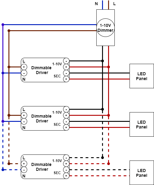
Pfi Panel Wiring Diagram. • the diagram should show incoming power feeding a receptacle. 3 phase capacitor bank wiring diagram wiring diagram is a simplified conventional normal pictorial representation of an electrical circuit it shows the components of the circuit as simplified shapes and the expertise and signal friends between the devices. Always test for power before implementing any circuit wires. 3 phase capacitor bank wiring diagram find not guilty wiring diagram.
35 Solar Combiner Box Wiring Diagram Wiring Diagram Database From kovodym.blogspot.com
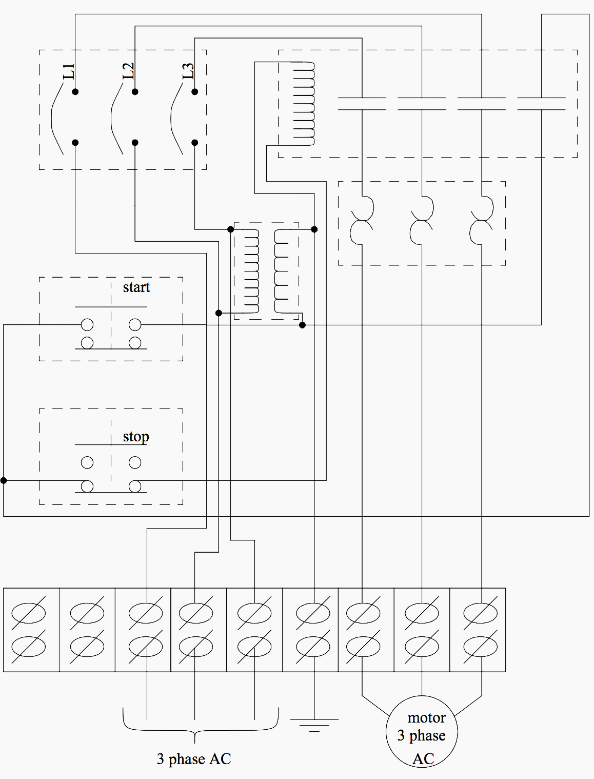
Basics 14 aov schematic (with block included) basics 15 wiring (or connection. The breakers are installed in a panel so that contact is made with one of two hot bus bars running down the middle of the box. This system uses 3 phase ac power (l1, l2 and l3) connected to the terminals. When you press the on push k1 contactor will hold and k1 no1 become. Based on the diagram, one of these wires with the tag 2 goes to the plc digital input. The wires in the top terminal go out to the solar panels and the wires on the bottom terminals go back and tie in to the utility.
Either way, our pdf is completely free.
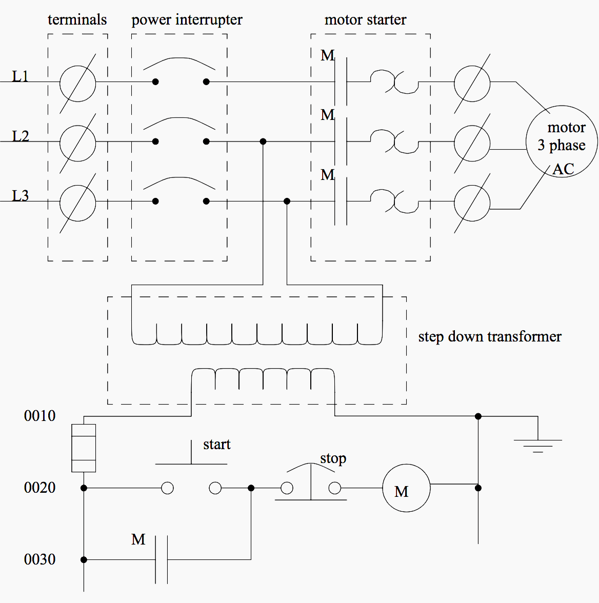
• have students produce a basic wiring diagram. In the back of the emergency stop push button, you see that we have four wires, just as what we have on the wiring diagram. An example of a wiring diagram for a motor controller is shown in figure 1. Dc wiring is done with / sqmm white wire. When you press the on push k1 contactor will hold and k1 no1 become. The three phases are then connected to a power interrupter.
 Source: youtube.com
Although electrical panels may not be overly complex from the. When you press the on push k1 contactor will hold and k1 no1 become. Electrical wiring installation photovoltaic photovoltaic cell pv solar & pv cell solar panel solar panel installation. Some vfds are having only one feedback relay, that time you just use the same for trip feedback. Please download these electrical control panel wiring diagram pdf by using the download button or right click on selected image then use save image menu.
 Source: pinterest.com
As electrical panels are what will contain control systems, panel wiring diagrams are commonly encountered by plc technicians and engineers. You can use edrawmax online or offline as it comes with a desktop app as well. Siemens main breaker kits are used as a replacement main. K1 no1, pb3, pb4, pb5 should be of potential free contact. Power control centre panel (pcc) / motor controller center panel (mcc) control wiring is carried with minimum sqmm gray wire & ct wiring is done with sqmm gray wires.
 Source: instructables.com
3 phase capacitor bank wiring diagram find not guilty wiring diagram. Vfd start stop wiring diagram. The fuse panelshould be mounted securely to a flat surface care should be taken to keep it and the wires away from moving objectssuch as gas and. You can use edrawmax online or offline as it comes with a desktop app as well. 3 phase capacitor bank wiring diagram find not guilty wiring diagram.
 Source: untpikapps.com
You can use edrawmax online or offline as it comes with a desktop app as well. Always test for power before implementing any circuit wires. • from the receptacle the cable feeds a switch. Renogy 200 watt 12 volt solar starter kit solartech direct i power my workshop with solar. 100 amp service panel wiring diagram.
 Source: untpikapps.com
The wires in the top terminal go out to the solar panels and the wires on the bottom terminals go back and tie in to the utility. • from the receptacle the cable feeds a switch. • from the switch the cable feeds a light. Electrical panel wiring diagrams are used to outline each device, as well as the connection between the devices found within an electrical panel. 3 set pilot device a contacts to.
 Source: pinterest.com
3 phase capacitor bank wiring diagram find not guilty wiring diagram. • from the receptacle the cable feeds a switch. Please download these electrical control panel wiring diagram pdf by using the download button or right click on selected image then use save image menu. Not merely will it assist you to accomplish your required final results quicker, but. Dashed lines indicate a single purchased component.
 Source: untpikapps.com
12 circuit wiring harness diagram. Electrical wiring installation photovoltaic photovoltaic cell pv solar & pv cell solar panel solar panel installation. 12 circuit wiring harness diagram. The fuse panelshould be mounted securely to a flat surface care should be taken to keep it and the wires away from moving objectssuch as gas and. 3 set pilot device a contacts to.
 Source: bengalss.com
Not merely will it assist you to accomplish your required final results quicker, but. Basics 14 aov schematic (with block included) basics 15 wiring (or connection. Hello viewer in this video i will show you how to install pfi (power factor improvement. K1 no1, pb3, pb4, pb5 should be of potential free contact. In the back of the emergency stop push button, you see that we have four wires, just as what we have on the wiring diagram.
 Source: ledpanelstore.co.uk
Some vfds are having only one feedback relay, that time you just use the same for trip feedback. Not merely will it assist you to accomplish your required final results quicker, but. 3 phase capacitor bank wiring diagram find not guilty wiring diagram. Vfd start stop wiring diagram: There are two aspects of safety which concern us in the assembly of electrical equipment and control panels.
 Source: youtube.com
Dashed lines indicate a single purchased component. Power control centre panel (pcc) / motor controller center panel (mcc) control wiring is carried with minimum sqmm gray wire & ct wiring is done with sqmm gray wires. Fill cycle, tank full fig. K1 no1, pb3, pb4, pb5 should be of potential free contact. Basics 8 aov elementary & block diagram :
Source: homewiringdiagram.blogspot.com
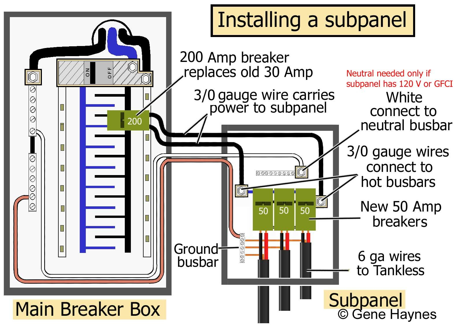
Rv solar panel wiring diagram pdf. Circuit breaker panel box wiring diagram this diagram illustrates some of the most common circuits found in a typical 200 amp circuit breaker service panel box. 100 amp service panel wiring diagram. Hello viewer in this video i will show you how to install pfi (power factor improvement. Class 9039 type x fig.
 Source: electrical-engineering-portal.com
15amp 20amp 30amp and 50amp as well as a gfci breaker and an isolated ground circuit. Although electrical panels may not be overly complex from the. Dashed lines indicate a single purchased component. How to wire a breaker box. 3 phase capacitor bank wiring diagram find not guilty wiring diagram.
 Source: pinterest.co.uk
Basics 14 aov schematic (with block included) basics 15 wiring (or connection. Hello viewer in this video i will show you how to install pfi (power factor improvement. Always test for power before implementing any circuit wires. 3 set pilot device a contacts to. Renogy 200 watt 12 volt solar starter kit solartech direct i power my workshop with solar.
 Source: wiringdiagramall.blogspot.com
Let’s see if we can find this wire. The breakers are installed in a panel so that contact is made with one of two hot bus bars running down the middle of the box. 12 circuit wiring harness diagram. Class 9039 type x fig. You can use edrawmax online or offline as it comes with a desktop app as well.
 Source: youtube.com
This is a pretty good amount of power and. 3 phase capacitor bank wiring diagram wiring diagram is a simplified conventional normal pictorial representation of an electrical circuit it shows the components of the circuit as simplified shapes and the expertise and signal friends between the devices. Connect or do wiring as per vfd side drawing, you take +24 v from the vfd pcb directly. Circuit breaker panel box wiring diagram this diagram illustrates some of the most common circuits found in a typical 200 amp circuit breaker service panel box. • the diagram should show incoming power feeding a receptacle.
 Source: wiringforums.com
Dc wiring is done with / sqmm white wire. The three phases are then connected to a power interrupter. Not merely will it assist you to accomplish your required final results quicker, but. Wiring diagram book a1 15 b1 b2 16 18 b3 a2 b1 b3 15 supply voltage 16 18 l m h 2 levels b2 l1 f u 1 460 v f u 2 l2 l3 gnd h1 h3 h2 h4 f u 3 x1a f u 4 f u 5 x2a r. This system uses 3 phase ac power (l1, l2 and l3) connected to the terminals.
 Source: electrical-engineering-portal.com
Basics 10 480 v pump schematic : Basics 9 4.16 kv pump schematic : This system uses 3 phase ac power (l1, l2 and l3) connected to the terminals. The three phases are then connected to a power interrupter. Either way, our pdf is completely free.
 Source: annawiringdiagram.com
Please download these electrical control panel wiring diagram pdf by using the download button or right click on selected image then use save image menu. 3 phase pole lighting wiring diagram manual automatic | light automatic | by tech bondhon Rv solar panel wiring diagram pdf. • the wiring diagram will show the circuit students will wire in wiring devices and wiring a wall section. How to wire a breaker box.
This site is an open community for users to do sharing their favorite wallpapers on the internet, all images or pictures in this website are for personal wallpaper use only, it is stricly prohibited to use this wallpaper for commercial purposes, if you are the author and find this image is shared without your permission, please kindly raise a DMCA report to Us.
If you find this site value, please support us by sharing this posts to your favorite social media accounts like Facebook, Instagram and so on or you can also save this blog page with the title pfi panel wiring diagram by using Ctrl + D for devices a laptop with a Windows operating system or Command + D for laptops with an Apple operating system. If you use a smartphone, you can also use the drawer menu of the browser you are using. Whether it’s a Windows, Mac, iOS or Android operating system, you will still be able to bookmark this website.
Category
Related By Category
- Predator 670 engine wiring diagram Idea
- Frsky x8r wiring diagram information
- Pioneer ts wx130da wiring diagram Idea
- Johnson 50 hp wiring diagram Idea
- Kohler voltage regulator wiring diagram Idea
- Johnson 50 hp outboard wiring diagram information
- Kti hydraulic remote wiring diagram Idea
- Pyle plpw12d wiring diagram information
- Tx9600ts wiring diagram information
- Lifan 50cc wiring diagram information