Peco point wiring diagram information
Home » Trend » Peco point wiring diagram information
Your Peco point wiring diagram images are available. Peco point wiring diagram are a topic that is being searched for and liked by netizens now. You can Get the Peco point wiring diagram files here. Download all free images.
If you’re looking for peco point wiring diagram images information related to the peco point wiring diagram interest, you have pay a visit to the right blog. Our site frequently provides you with suggestions for downloading the maximum quality video and image content, please kindly hunt and locate more enlightening video content and images that fit your interests.
Peco Point Wiring Diagram. Wiring existing n scale layout to dcc. A wiring diagram usually gives opinion very nearly the relative approach and bargain of devices and. Recently peco have moved to unifrog construction, but the basic notes here apply in the same way. From early days, peco has concentrated its manufacturing skills on producing trackwork for the model railway enthusiast.
 Point control_2 From bpodmore.co.uk
Peco pl 11 side mounted turnout motor electrics dc getting you started your model railway club. Sometimes, they can be quite stiff to move. Struggle to get your head around how to wire up live frog electrofrog poi. Stud and probe operation is favoured by many people and is ideal when a control panel with track diagram is used, the studs being. Peco pl 15 1 x point motor accessory twin micro switch for 10 or 10e. The basics of wiring a turnout correctly.
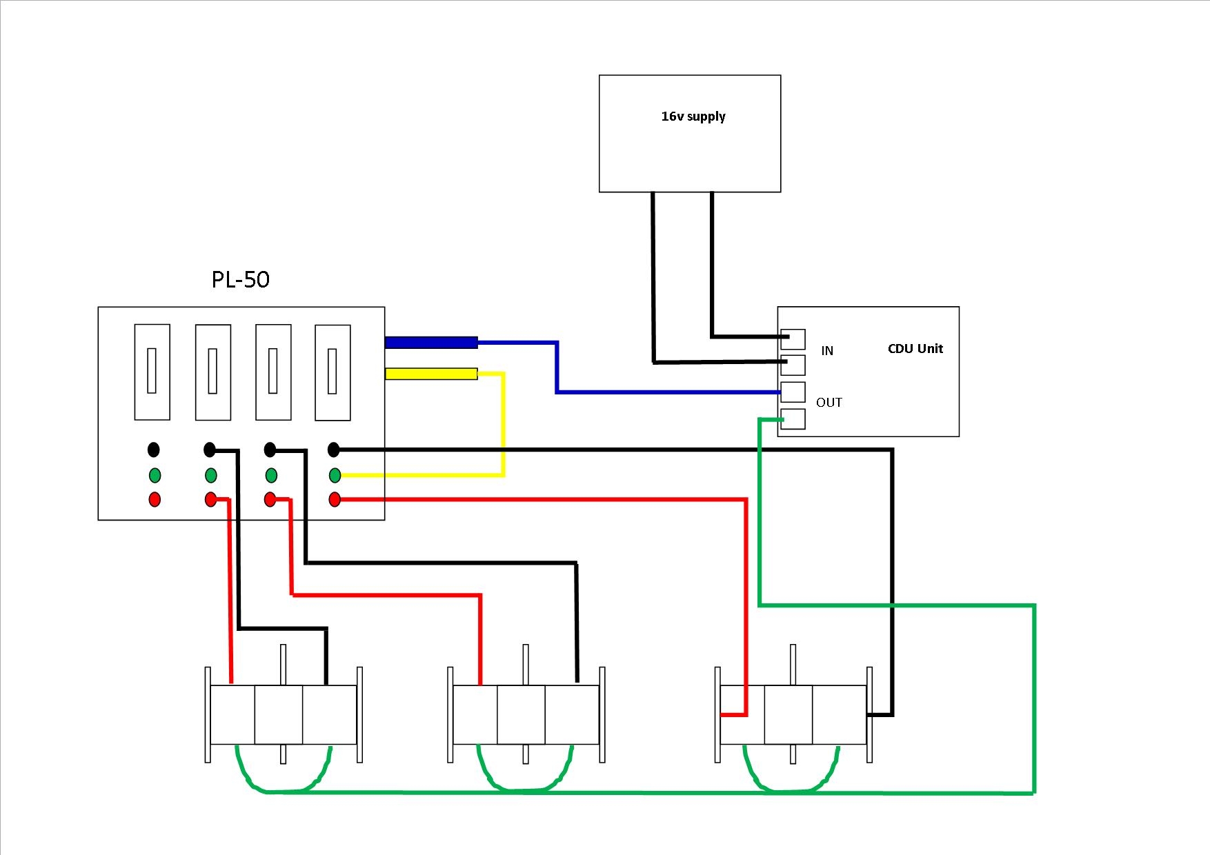
Point motors part 1 solenoid basics wiring gaugemaster pm 10 indicators seep motor for dc diagram pengkabelan digital kontrol electrical wires cable model railway train books utit vn wire peco code 55 frogs circuitron tortoise cdu with spdt switch pl 50 turnout points module 11 side mounted older lgb switches g.
That bulletin also includes how to improve the look of a peco point, so the more adventurous among you might like to check it out! Wiring existing n scale layout to dcc. Struggle to get your head around how to wire up live frog electrofrog poi. The rails motors are far more efficient but they wire exactly the same. The wiring of these new turnouts is a development of both the insulfrog and electrofrog designs. Recently peco have moved to unifrog construction, but the basic notes here apply in the same way.
 Source: wayofok.blogspot.com
On the peco pl11 surface mounting motor the following wiring colours are used. So i would like to see a diagram of how it is wired. Point motors part 1 solenoid basics wiring gaugemaster pm 10 and cdu to 2 terminal push make switches questions answers irish railway modeller indicators seep motor. The wiring diagram with the cdu looks like it uses a buss type wiring plan but i think this is an over simplification. Stud and probe points operation.
 Source: rmweb.co.uk
Struggle to get your head around how to wire up live frog electrofrog poi. The wiring diagram with the cdu looks like it uses a buss type wiring plan but i think this is an over simplification. We also cover this subject in detail in another advice chapter “advice #2—making peco better”. Edited may 26, 2017 by bertiedog. Wiring for standard 12v dc systems.
 Source: hattons.co.uk
A little explanation on how i wire up my 3 way points. Wiring diagram digital command control electrical wires cable electric motor binary decoder png. There are a few reasons for the confusion. In general, we found the switches to be quite reliable. For those who use a different form of point operation a micro switch can be mounted on the end of the tie bar to perform the same function.
 Source: rmweb.co.uk
Wiring diagram for peco point motors. You can see the typical wiring of most styles of solenoid point motors on my web site.my web sites point motor wiring scroll down a little to see the pl11 wiring diagram. The diodes as shown in the diagram are the correct way round (silver ring on the end is furthest from the point motor). There are a few reasons for the confusion. Basic point wiring diagram with hornby r044 passing contact switch.
.gif “Wiring Diagram For Peco Point Motors”) Source: wiringdiagramall.blogspot.com
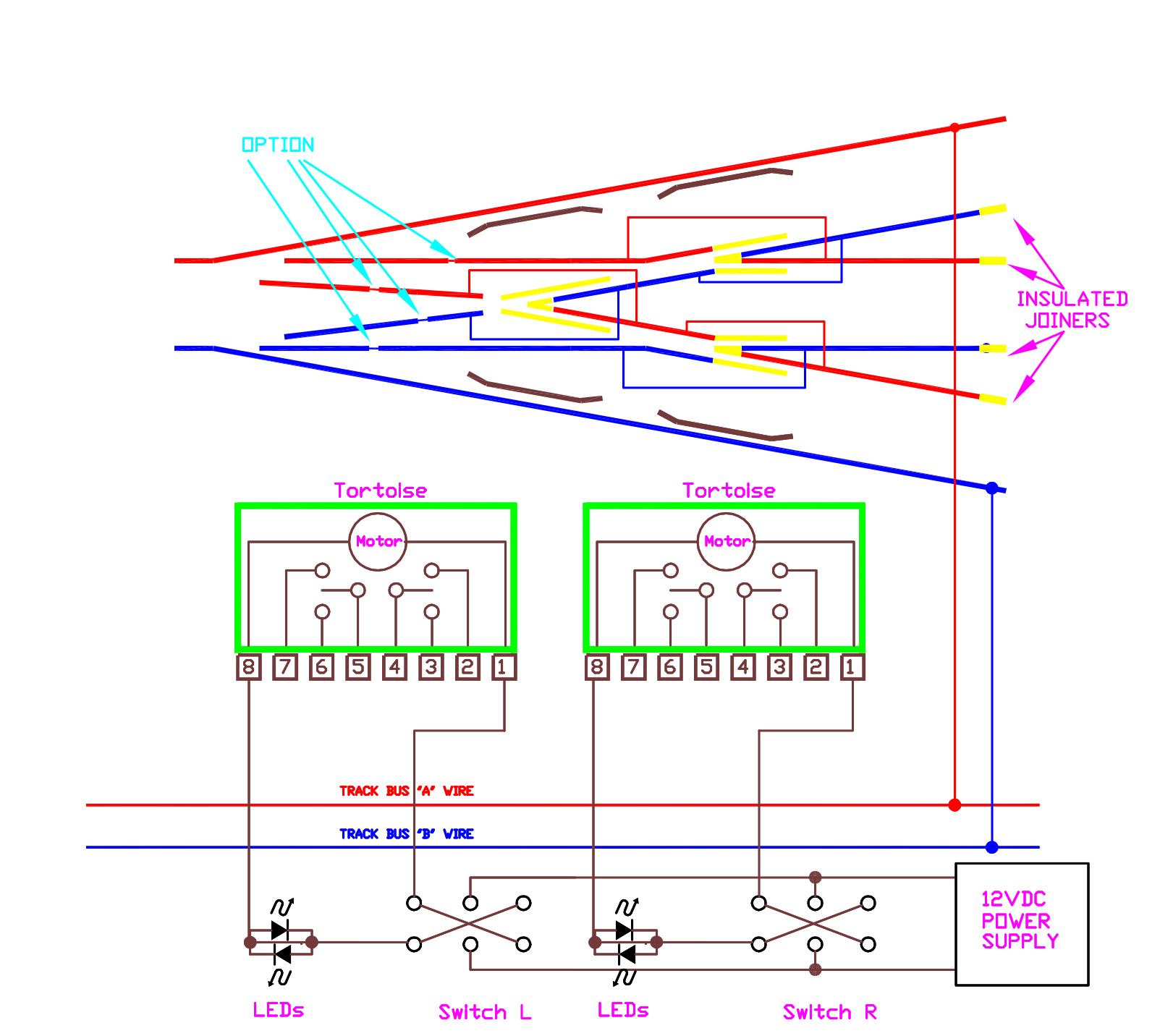
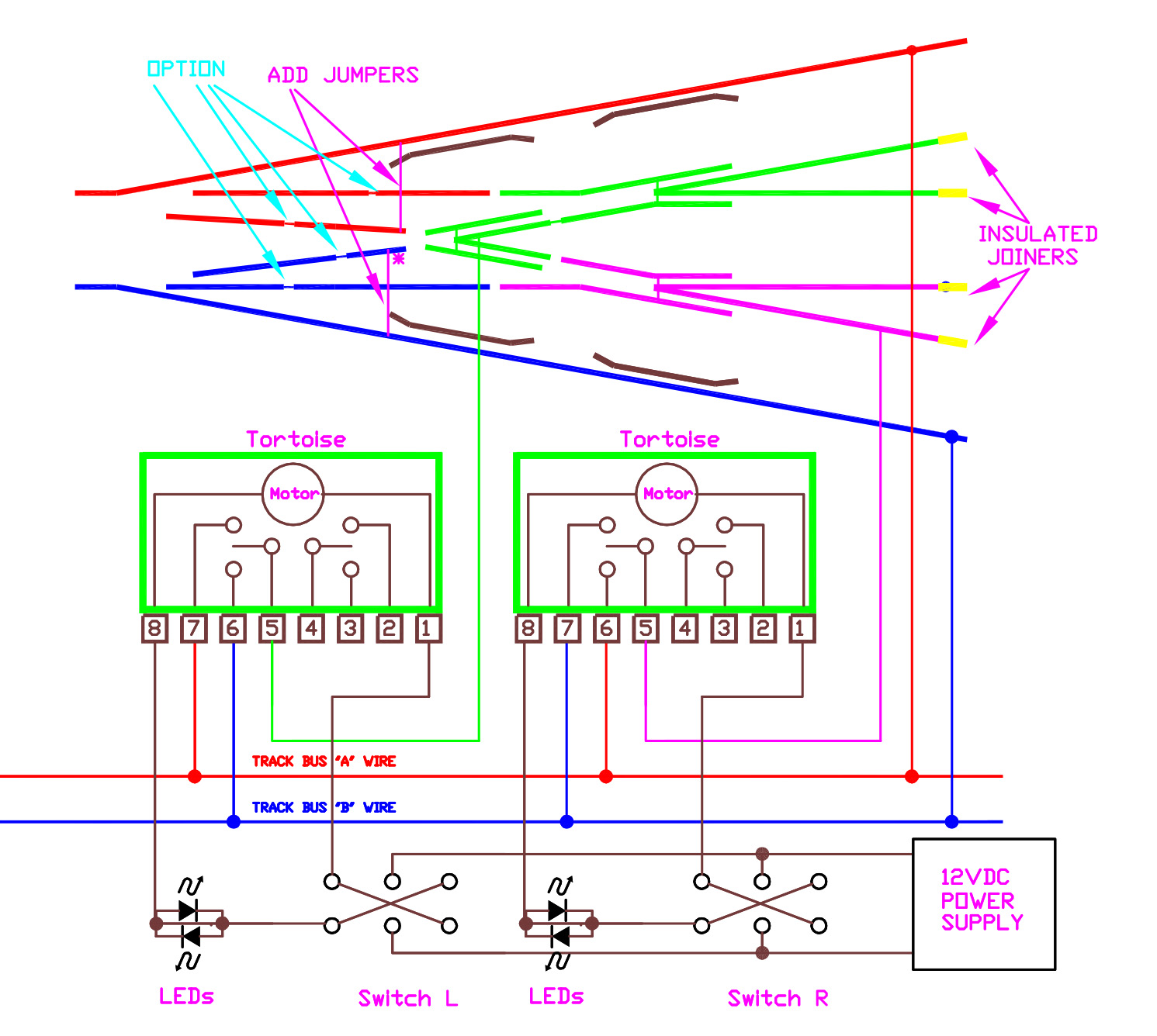
Wiring for standard 12v dc systems. Also, depending on your orientation of your tortoises, thw wires to terminals 6 and 7 may have to be reversed on one or the other tortoise. In general, we found the switches to be quite reliable. Struggle to get your head around how to wire up live frog electrofrog poi. The pl 13 accessory switch is unsuitable for this purpose.
 Source: bpodmore.co.uk
The wiring diagram with the cdu looks like it uses a buss type. That bulletin also includes how to improve the look of a peco point, so the more adventurous among you might like to check it out! Here is a video response for kevin a friend of mine on here to show how easy it is to install a peco pl 11 side mount point motor.hope you enjoy the video pl. The business started trading in 1946 and is now in its third generation. On the peco pl11 surface mounting motor the following wiring colours are used.
.gif “Electrical Page 3”) Source: brian-lambert.co.uk
It should work now if it did. Recently peco have moved to unifrog construction, but the basic notes here apply in the same way. Wiring diagrams and notes to follow in the morning or later today. By the way the symmetrical 3 way is insulfrog only as far as i know. Unifrog is basically a live frog design that can, by not connecting the frog, behave as both live and dead.
 Source: wiringdiagram.2bitboer.com
For information on wiring turnouts go to the section on wiring turnouts. A little explanation on how i wire up my 3 way points. Finally, if the frog is live, wire up a frog feed from a frog polarity switch or a frog juicer. From early days, peco has concentrated its manufacturing skills on producing trackwork for the model railway enthusiast. Wiring diagram electrical wires cable switches png 1005x691px area direct cur.
 Source: rmweb.co.uk
We also cover this subject in detail in another advice chapter “advice #2—making peco better”. A wiring diagram usually gives opinion very nearly the relative approach and bargain of devices and. Wiring existing n scale layout to dcc. The diodes as shown in the diagram are the correct way round (silver ring on the end is furthest from the point motor). There are a few reasons for the confusion.
 Source: rmweb.co.uk
Finally, if the frog is live, wire up a frog feed from a frog polarity switch or a frog juicer. On the peco pl11 surface mounting motor the following wiring colours are used. The wire attached to the frog (7) is necessary only if you are using dcc or are experiencing short circuits. So i would like to see a diagram of how it is wired. The basics of wiring a turnout correctly.
 Source: wayofok.blogspot.com
So i would like to see a diagram of how it is wired. For those who use a different form of point operation a micro switch can be mounted on the end of the tie bar to perform the same function. Unifrog is basically a live frog design that can, by not connecting the frog, behave as both live and dead. It shows the components of the circuit as simplified shapes, and the faculty and signal friends amongst the devices. Just a simple push fit onto the motor terminals;
 Source: wayofok.blogspot.com
Stud and probe points operation. For those who use a different form of point operation a micro switch can be mounted on the end of the tie bar to perform the same function. Wiring for dcc peco switches. It should work now if it did. Peco pl 11 side mounted turnout motor electrics dc getting you started your model railway club.
.gif “way Peco 3 Way Point Wiring Diagram”) Source: wayofok.blogspot.com
It should work now if it did. Edited may 26, 2017 by bertiedog. Finally, if the frog is live, wire up a frog feed from a frog polarity switch or a frog juicer. Struggle to get your head around how to wire up live frog electrofrog poi. Peco pl 11 side mounted turnout motor electrics dc getting you started your model railway club.
.gif “Electrical Page 2”) Source: brian-lambert.co.uk
Wiring for dcc peco switches. The wiring of these new turnouts is a development of both the insulfrog and electrofrog designs. Also, depending on your orientation of your tortoises, thw wires to terminals 6 and 7 may have to be reversed on one or the other tortoise. Just a simple push fit onto the motor terminals; Peco turnouts cause a lot of confusion but fundamentally, all peco turnouts can be used with dcc.
 Source: wiringfordcc.com
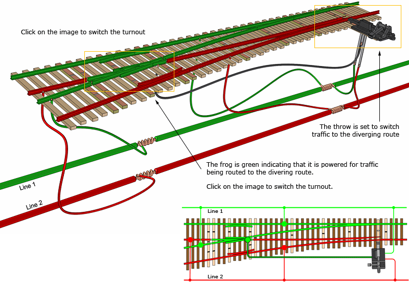
Wiring existing n scale layout to dcc. Unifrog is basically a live frog design that can, by not connecting the frog, behave as both live and dead. As supplied, the turnout is wired completely “live”, except for the frog tip and wing rails, and can be used straight out of the packet without. Peco pl 15 1 x point motor accessory twin micro switch for 10 or 10e. The basis of wiring a layout with live frogs (see figure 3) is that the current must always be fed (a) to the toe end of each turnout (b).
 Source: model-railroad-hobbyist.com
For those who use a different form of point operation a micro switch can be mounted on the end of the tie bar to perform the same function. Wiring for dcc peco switches. The wire attached to the frog (7) is necessary only if you are using dcc or are experiencing short circuits. There is insufficient travel of the point motor armature extension to guarantee There are a few reasons for the confusion.
 Source: wiringdiagramall.blogspot.com
The basis of wiring a layout with live frogs (see figure 3) is that the current must always be fed (a) to the toe end of each turnout (b). Peco pl 15 1 x point motor accessory twin micro switch for 10 or 10e. For information on wiring turnouts go to the section on wiring turnouts. Here is a video response for kevin a friend of mine on here to show how easy it is to install a peco pl 11 side mount point motor.hope you enjoy the video pl. The wire attached to the frog (7) is necessary only if you are using dcc or are experiencing short circuits.
 Source: rmweb.co.uk
On the peco pl11 surface mounting motor the following wiring colours are used. On the peco pl11 surface mounting motor the following wiring colours are used. There are a few reasons for the confusion. By the way the symmetrical 3 way is insulfrog only as far as i know. Wiring for standard 12v dc systems.
This site is an open community for users to do submittion their favorite wallpapers on the internet, all images or pictures in this website are for personal wallpaper use only, it is stricly prohibited to use this wallpaper for commercial purposes, if you are the author and find this image is shared without your permission, please kindly raise a DMCA report to Us.
If you find this site helpful, please support us by sharing this posts to your preference social media accounts like Facebook, Instagram and so on or you can also save this blog page with the title peco point wiring diagram by using Ctrl + D for devices a laptop with a Windows operating system or Command + D for laptops with an Apple operating system. If you use a smartphone, you can also use the drawer menu of the browser you are using. Whether it’s a Windows, Mac, iOS or Android operating system, you will still be able to bookmark this website.
Category
Related By Category
- Predator 670 engine wiring diagram Idea
- Frsky x8r wiring diagram information
- Pioneer ts wx130da wiring diagram Idea
- Johnson 50 hp wiring diagram Idea
- Kohler voltage regulator wiring diagram Idea
- Johnson 50 hp outboard wiring diagram information
- Kti hydraulic remote wiring diagram Idea
- Pyle plpw12d wiring diagram information
- Tx9600ts wiring diagram information
- Lifan 50cc wiring diagram information