Notifier smoke detector wiring diagram Idea
Home » Trend » Notifier smoke detector wiring diagram Idea
Your Notifier smoke detector wiring diagram images are ready. Notifier smoke detector wiring diagram are a topic that is being searched for and liked by netizens today. You can Download the Notifier smoke detector wiring diagram files here. Download all royalty-free vectors.
If you’re looking for notifier smoke detector wiring diagram pictures information linked to the notifier smoke detector wiring diagram interest, you have pay a visit to the right site. Our site always gives you hints for seeing the highest quality video and picture content, please kindly search and locate more enlightening video content and graphics that fit your interests.
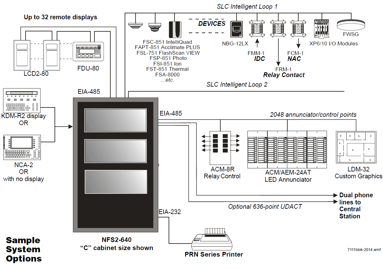
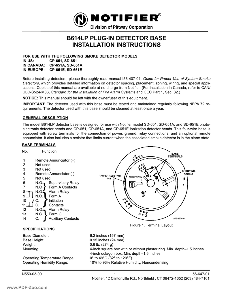
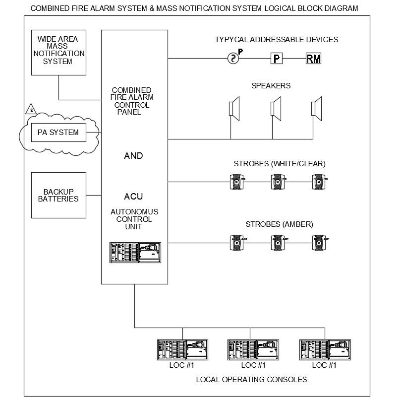
Notifier Smoke Detector Wiring Diagram. Gst addressable smoke detector wiring diagram. It consists of a combined transmitter/receiver unit and a reflector. To 9 other detectors in the loop for multiple fan shut down. Some panels support extended addressing.
 Get Fire Alarm Pull Station Wiring Diagram Download From worldvisionsummerfest.com
Notifier recommends spacing detectors in compliance with nfpa 72. Set the address on the module per job drawings. Duct smoke detector wiring diagram. Removal of flashscan® series detector heads from base in high ceiling installations. See duct smoke detectors applications guide hvag53 for details on pendant mount applications. In the addressable fire detection system, the fire alarm wiring schematic diagram as described below:
Wire external power to the unit via the power terminals.
Limit wire runs to 25 ohms. In our basic wiring diagram, a single or multiple heat and smoke detectors are installed in the home by connecting the live (line or hot), neutral, ground and an interconnected wire to the alarm. Check the zone wiring before installing the smoke detector head. A smoke or heat detector can be installed to the existing or new home wiring. These products are not listed for use inside duct smoke detectors. Canned aerosol simulated smoke (canned smoke agent) formulas will vary by manufacturer.
 Source: worldvisionsummerfest.com
Smoke detectors designed for use in air duct systems are used to sense the presence of smoke in the duct. To 9 other detectors in the loop for multiple fan shut down. System smoke detector application guide, For specific information regarding detector spacing, placement, and special applications refer to nfpa 72. Set the address on the module per job drawings.
 Source: wiringall.com
Set the desired address on the sensor address switches. To 9 other detectors in the loop for multiple fan shut down. Electrical ratings power supply voltage: Check the zone wiring before installing the smoke detector head. A smoke or heat detector can be installed to the existing or new home wiring.
 Source: firealarmsonline.com
In our basic wiring diagram a single or multiple heat and smoke detectors are installed in the home by connecting the live line or hot neutral ground and an interconnected wire to the alarm. When the obscuration reaches the alarm threshold, selected at the transmitter/receiver unit, the detector Each detector has 4 connections (2 inputs & 2 outputs) the connection is done in the detector body. For specific information regarding detector spacing, placement, and special applications refer to nfpa 72. Smoke detector designed to provide open area protection.
 Source: foxvalleyfire.com
See duct smoke detectors applications guide hvag53 for details on pendant mount applications. Removal of flashscan® series detector heads from base in high ceiling installations. Wire the sensor base (supplied separately) per the wiring diagram. System smoke detector application guide, Misuse or overuse of these products may have long term adverse effects on the smoke detector.
 Source: bengalss.com
Duct smoke detector wiring diagram. Duct smoke detector wiring diagrams. In low airflow applications with smooth ceiling, space detectors 30 feet (9.144m) for ceiling heights 10 feet (3.148m) and higher. It consists of a combined transmitter/receiver unit and a reflector. For specific information regarding detector spacing, placement, and special applications refer to nfpa 72.
 Source: pinterest.com
Or the system smoke detector application guide, available from notifier. For more detail, please refer to the product guide. Smoke entering the area between the two components causes a reduction in the signal returned to the receiver. Removal of flashscan® series detector heads from base in high ceiling installations. Notifier recommends spacing detectors in compliance with nfpa 72.
 Source: ricardolevinsmorales.com
The 2351e photoelectric smoke detector forms part of the series 300 range of conventional detectors. Misuse or overuse of these products may have long term adverse effects on the smoke detector. These products are not listed for use inside duct smoke detectors. In low airflow applications with smooth ceiling, space detectors 30 feet (9.144m) for ceiling heights 10 feet (3.148m) and higher. Install the sensor in to the sensor base.
 Source: electricaltechnology.org
A green led flashes to indicate power, a In order to set the module above address 99 on compatible systems, carefully remove the stop on the upper rotary Check the zone wiring before installing the smoke detector head. Use the slot in the retaining clip to hold the spring against the terminal, as shown in figure 1. Wire the remote indicator (b), heater power supply (c) and external reset input (d) if required.
 Source: expiredmormonfemale.blogspot.com
A sensor that fails any of these tests may. A wiring diagram is a simplified traditional pictorial depiction of an electric circuit. Wire external power to the unit via the power terminals. Some guards listed below may not be applicable to fst series. Push the sensor into the base while turning it clockwise to secure it in place.
 Source: foxvalleyfire.com
To 9 other detectors in the loop for multiple fan shut down. A wiring diagram is a simplified traditional photographic depiction. In low airflow applications with smooth ceiling, space detectors 30 feet (9.144m) for ceiling heights 10 feet (3.148m) and higher. Smoke detector designed to provide open area protection. Smoke entering the area between the two components causes a reduction in the signal returned to the receiver.
 Source: electricaltechnology.org
Smoke entering the area between the two components causes a reduction in the signal returned to the receiver. These products are not listed for use inside duct smoke detectors. For specific information regarding detector spacing, placement, and special applications refer to nfpa 72. Plications, refer to nfpa 72 or the system smoke detector application guide, available from notifier. The cabinet provides ample room for wire routing, keeping wiring neat at all times.
 Source: wiringall.com
Gst addressable smoke detector wiring diagram. Smoke detector designed to provide open area protection. Some guards listed below may not be applicable to fst series. A wiring diagram is a simplified traditional pictorial depiction of an electric circuit. Limit wire runs to 25 ohms.
 Source: blogmaygomes.blogspot.com
A wiring diagram is a simplified traditional photographic depiction. Set the desired address on the sensor address switches. Canned aerosol simulated smoke (canned smoke agent) formulas will vary by manufacturer. This unit senses smoke in the most challenging conditions operating in airflow speeds of 100 to 4000 feet per. In the addressable fire detection system, the fire alarm wiring schematic diagram as described below:
 Source: wholefoodsonabudget.com
A green led flashes to indicate power, a This is the basic fire alarm system used in household wiring. A wiring diagram is a simplified traditional photographic depiction. Duct smoke detector wiring diagram. Duct smoke detector wiring diagrams.
 Source: bengalss.com
The duct smoke detector latches into alarm state when an alarm occurs. A green led flashes to indicate power, a The duct smoke detector latches into alarm state when an alarm occurs. Gst addressable smoke detector wiring diagram. It consists of a combined transmitter/receiver unit and a reflector.
 Source: cadbull.com
Duct smoke detector wiring diagrams. The cabinet provides ample room for wire routing, keeping wiring neat at all times. System sensor smoke detector wiring diagram system sensor convention 4 wire duct smoke detector d4120 wiring fancy. In the addressable fire detection system, the fire alarm wiring schematic diagram as described below: Some guards listed below may not be applicable to fst series.
 Source: pinterest.es
Each detector has 4 connections (2 inputs & 2 outputs) the connection is done in the detector body. Canned aerosol simulated smoke (canned smoke agent) formulas will vary by manufacturer. Set the desired address on the sensor address switches. A sensor that fails any of these tests may. The 2351e photoelectric smoke detector forms part of the series 300 range of conventional detectors.
 Source: wiringall.com
Smoke detector designed to provide open area protection. For more detail, please refer to the product guide. Electrical ratings power supply voltage: The photocell conducts as long as the light falls on it. System sensor smoke detector wiring diagram system sensor convention 4 wire duct smoke detector d4120 wiring fancy.
This site is an open community for users to do sharing their favorite wallpapers on the internet, all images or pictures in this website are for personal wallpaper use only, it is stricly prohibited to use this wallpaper for commercial purposes, if you are the author and find this image is shared without your permission, please kindly raise a DMCA report to Us.
If you find this site helpful, please support us by sharing this posts to your favorite social media accounts like Facebook, Instagram and so on or you can also save this blog page with the title notifier smoke detector wiring diagram by using Ctrl + D for devices a laptop with a Windows operating system or Command + D for laptops with an Apple operating system. If you use a smartphone, you can also use the drawer menu of the browser you are using. Whether it’s a Windows, Mac, iOS or Android operating system, you will still be able to bookmark this website.
Category
Related By Category
- Predator 670 engine wiring diagram Idea
- Frsky x8r wiring diagram information
- Pioneer ts wx130da wiring diagram Idea
- Johnson 50 hp wiring diagram Idea
- Kohler voltage regulator wiring diagram Idea
- Johnson 50 hp outboard wiring diagram information
- Kti hydraulic remote wiring diagram Idea
- Pyle plpw12d wiring diagram information
- Tx9600ts wiring diagram information
- Lifan 50cc wiring diagram information