Nos progressive controller wiring diagram information
Home » Trending » Nos progressive controller wiring diagram information
Your Nos progressive controller wiring diagram images are available. Nos progressive controller wiring diagram are a topic that is being searched for and liked by netizens today. You can Download the Nos progressive controller wiring diagram files here. Find and Download all royalty-free vectors.
If you’re looking for nos progressive controller wiring diagram pictures information connected with to the nos progressive controller wiring diagram interest, you have visit the right blog. Our website frequently gives you hints for refferencing the highest quality video and image content, please kindly hunt and locate more informative video content and graphics that match your interests.
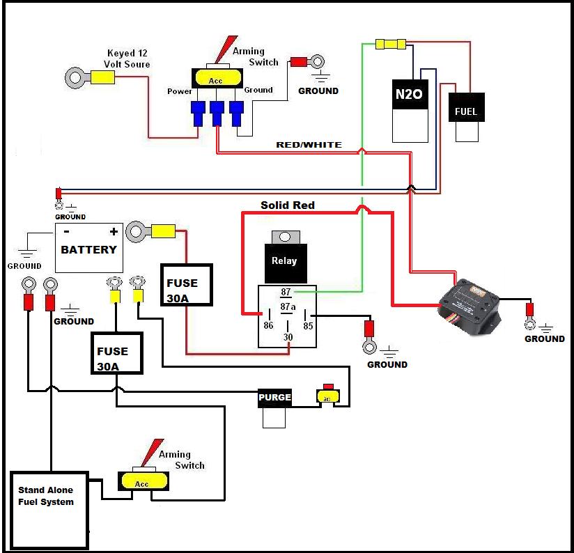
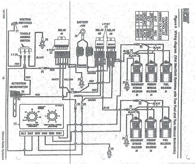
Nos Progressive Controller Wiring Diagram. Wire the maximiser as shown in the following wiring diagrams. Each channel can drive a fuel or nitrous solenoid progressively. 1) bottom view of all relays 2) all relays must be diode suppressed n4~n 2o n4~n 2o. Wiring diagram model (1) author:

The diagrams are marked what color wires go to things like your various sensors, transbrake, and nitrous system accessories. Ramp time is adjustable from 0 to 4.5. Nitrous outlet — universal single stage wiring diagram company / contact: Progressive nitrous controller contains high frequency digital installation of this edelbrock product signifies that you have read this document and agree to the terms. Trans brake 12 volt solenoids solenoid battery ground battery ground wiring diagram for n 2o with transbrake nos p/n nos p/n notes: Arc pressure switch kit wiring.
Trans brake 12 volt solenoids solenoid battery ground battery ground wiring diagram for n 2o with transbrake nos p/n nos p/n notes:
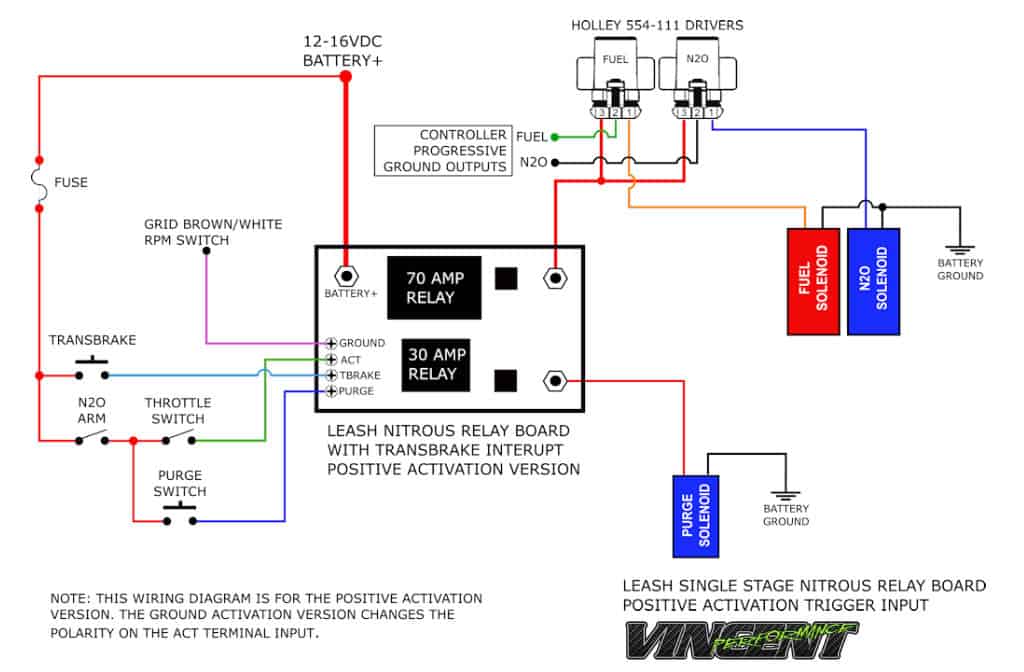
Leash dual stage nitrous controller wiring diagram color bare billet aluminum finish, black, lime green, red, blue, pink, yellow, white, silver vein, charcoal, silver spatter, gray, orange The progression ramp automatically starts at 20% and ends at 100% when you push the accelerator pedal to w.o.t. Leash dual stage nitrous controller wiring diagram color bare billet aluminum finish, black, lime green, red, blue, pink, yellow, white, silver vein, charcoal, silver spatter, gray, orange Trans brake 12 volt solenoids solenoid battery ground battery ground wiring diagram for n 2o with transbrake nos p/n nos p/n notes: Tyco 75 amp relay schematic. Wire, wire labels, crimp terminals, fuses, switches, and relays.
 Source: ls1tech.com
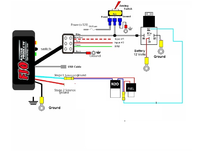
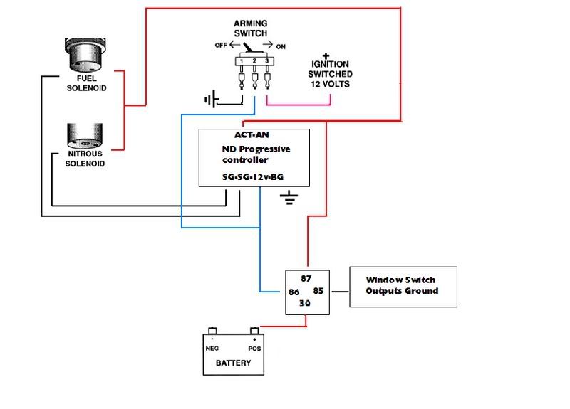
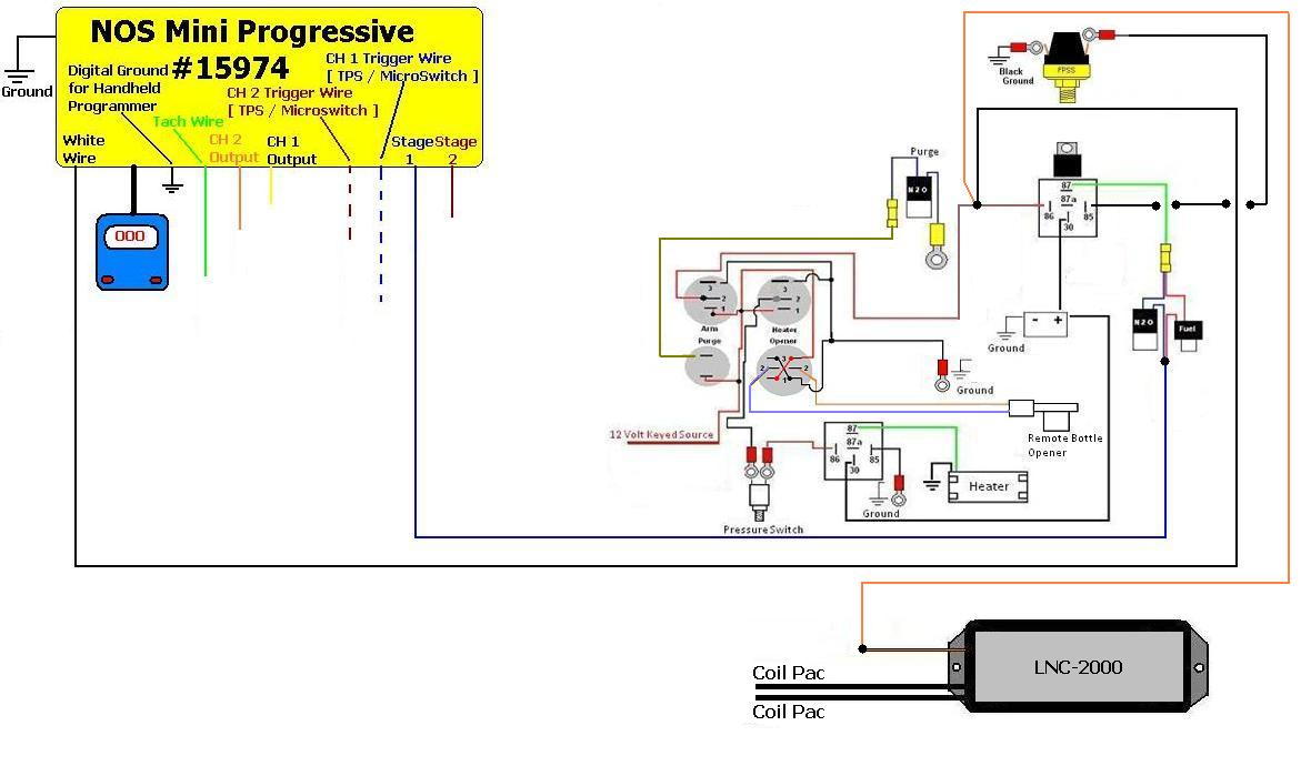
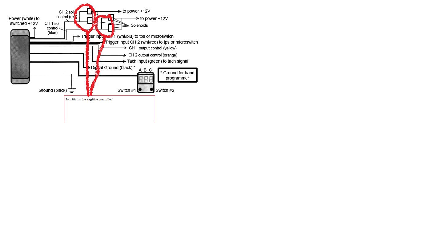
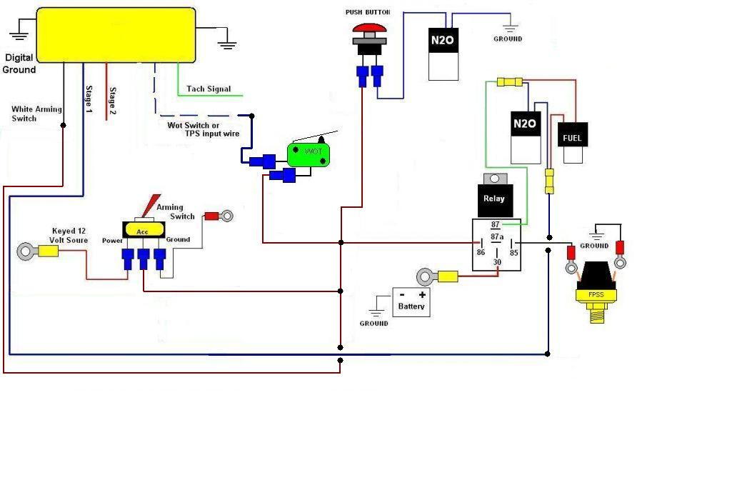
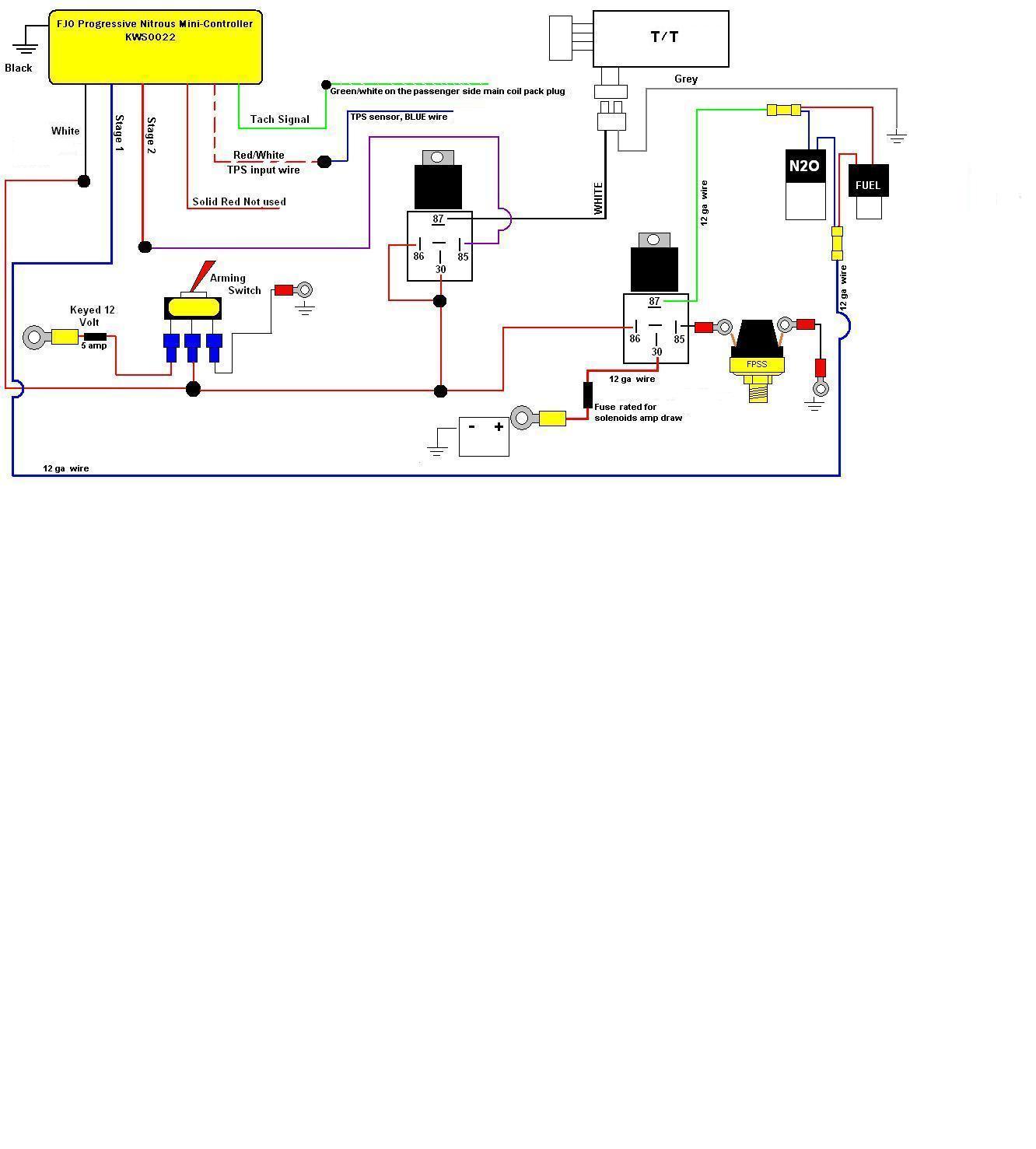
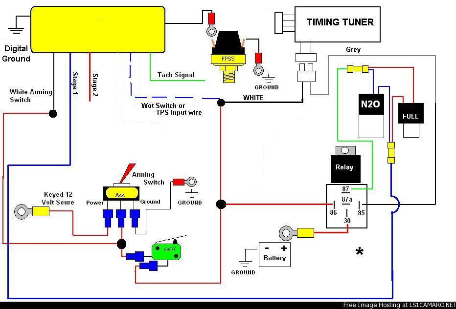
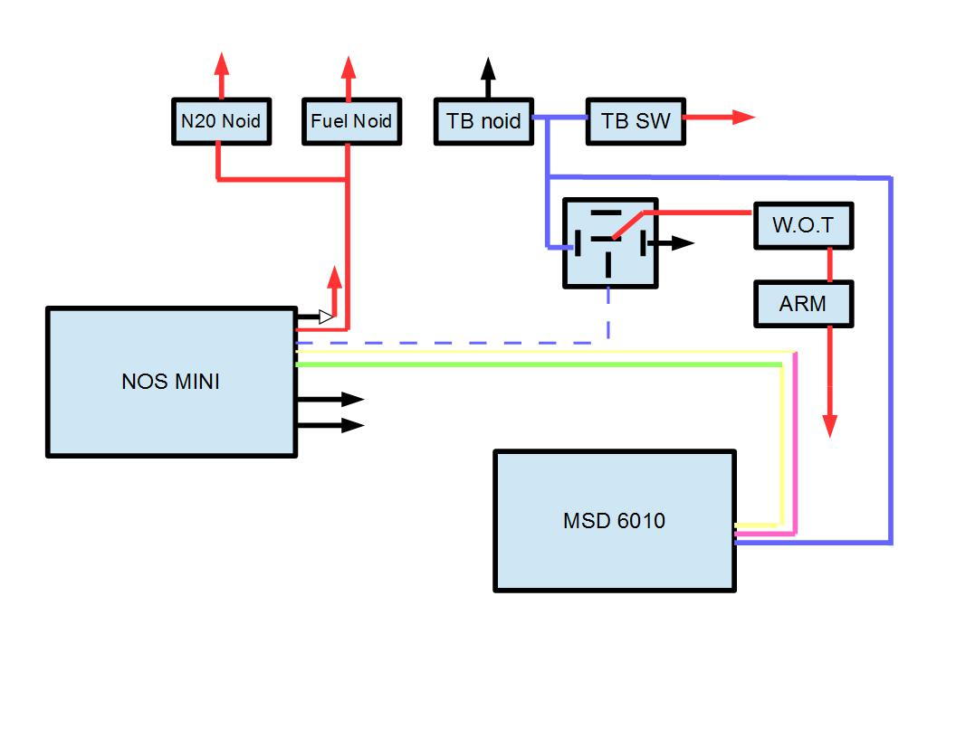
Progressive wiring diagrams using controller and driver 5. Nitrous outlet promax progressive controller. The progression ramp automatically starts at 20% and ends at 100% when you push the accelerator pedal to w.o.t. Nos progressive wiring diagram #1 post by chpcamaro » tue apr 28, 2009 5:59 am i figure this might help some people with wiring there nos progressive so i thought i would share my wiring diagram remember nos uses a ground switch to activate the progressive On nos launcher wiring diagram.
 Source: ls1tech.com
Ramp time is adjustable from 0 to 4.5. Single stage nos system with transbrake interrupt relay, msd window switch, and dynotune delay timer. To complete the installation, you will require: Wire the maximiser as shown in the following wiring diagrams. If you have any questions, email daver@wiringall.com or call when wired in series with your nitrous system relay it will enable you plished by splicing into the trans brake solenoid wiring and using this power source to.
 Source: ls1tech.com
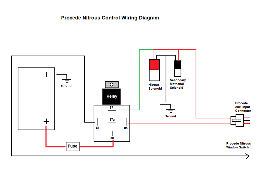
Nitrous wiring diagram with transbrake. If you have any questions, email daver@wiringall.com or call when wired in series with your nitrous system relay it will enable you plished by splicing into the trans brake solenoid wiring and using this power source to. Single stage nos system with transbrake interrupt relay, msd window switch, and dynotune delay timer. The shorter you keep the red, blue and black wires the more efficiently the unit will work. Wiring diagram model (1) author:
 Source: e90post.com
The shorter you keep the red, blue and black wires the more efficiently the unit will work. If you have any questions, email daver@wiringall.com or call when wired in series with your nitrous system relay it will enable you plished by splicing into the trans brake solenoid wiring and using this power source to. Two completely independent stages of nitrous/fuel control, each with independent throttle position activation switch and progressive ramps. Not following the advice below may result in system damage or at worst serious engine damage. Each channel can drive a fuel or nitrous solenoid progressively.
 Source: wiringall.com
Progressive wiring diagrams using controller and driver 5. Nitrous wiring diagram with transbrake. Software for programming controller and downloading logged data. Rev f blue tps wot input wire connection diagrams advanced programming options. Wiring with and without a progressive controller (transbrake) wiring with and without a progressive controller (no transbrake) multi stage system with progressors.
 Source: wiringschemas.blogspot.com
2o n/c n/o com trig gnd. The progression ramp automatically starts at 20% and ends at 100% when you push the accelerator pedal to w.o.t. Nitrous outlet — universal single stage wiring diagram company / contact: The stud labeled 2 is for the transbrake. This controller is capable of operating any nos nitrous
 Source: manualsdir.com
The progression ramp automatically starts at 20% and ends at 100% when you push the accelerator pedal to w.o.t. (dti) warrants the material and. Single stage nos system with transbrake interrupt relay. Progressive nitrous controller contains high frequency digital installation of this edelbrock product signifies that you have read this document and agree to the terms. On nos launcher wiring diagram.
 Source: ls1tech.com
- bottom view of all relays 2) all relays must be diode suppressed n4~n. 2o n/c n/o com trig gnd. Nos progressive wiring diagram #1 post by chpcamaro » tue apr 28, 2009 5:59 am i figure this might help some people with wiring there nos progressive so i thought i would share my wiring diagram remember nos uses a ground switch to activate the progressive This controller is capable of operating. 1) bottom view of all relays 2) all relays must be diode suppressed n4~n.
 Source: wiring.hpricorpcom.com
This controller is capable of operating any nos nitrous Blue tps wot input wire connection diagram standard programming option only, if using in progressive mode only! On nos launcher wiring diagram. Single stage nos system with transbrake interrupt relay. Et improvements of up to 1/2 second and more can be achieved with the simple addition of an nos progressive controller.
 Source: ls1tech.com
Single stage nos system with transbrake interrupt relay, msd window switch, and dynotune delay timer. Two completely independent stages of nitrous/fuel control, each with independent throttle position activation switch and progressive ramps. It features a black anodized, billet aluminum case and unique adjustment knobs that lock into place, so the progressive settings can�t accidentally be changed. Your nos progressive nitrous oxide injection controller is designed to provide you with an ability to “adjust” the rate at which power from your nitrous oxide injection kit is applied to your vehicle. 71900 progressive nitrous controller contains high frequency digital electronics and will not function correctly without suppression wires.
 Source: ls1tech.com
Not following the advice below may result in system damage or at worst serious engine damage. Trans brake 12 volt solenoids solenoid battery ground battery ground wiring diagram for n 2o with transbrake nos p/n nos p/n notes: This controller is capable of operating any nos nitrous Nos progressive wiring diagram #1 post by chpcamaro » tue apr 28, 2009 5:59 am i figure this might help some people with wiring there nos progressive so i thought i would share my wiring diagram remember nos uses a ground switch to activate the progressive The throttle position activation switch (tpas) accepts all analog throttle
 Source: ls1tech.com
Not following the advice below may result in system damage or at worst serious engine damage. 1) bottom view of all relays 2) all relays must be diode suppressed n4~n 2o n4~n 2o. 1) do not activate the unit without the black wire connected to ground. Wiring with and without a progressive controller (transbrake) wiring with and without a progressive controller (no transbrake) multi stage system with progressors. Not following the advice below may result in system damage or at worst serious engine damage.
 Source: pipeen.com
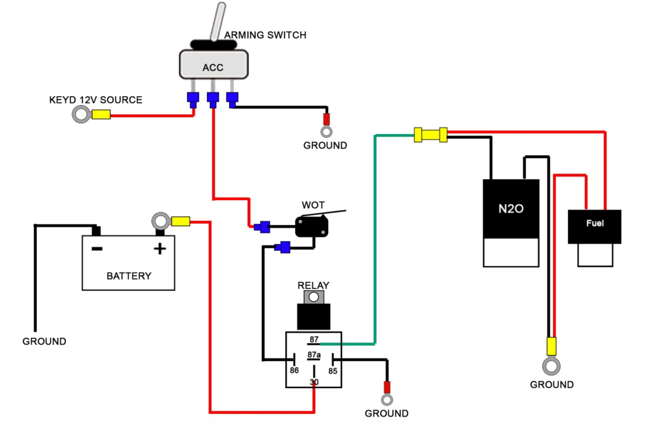
The activation trigger is typically connected to your nitrous system throttle switch, so choice if that is a positive or negative circuit. Trans brake 12 volt solenoids solenoid battery ground battery ground wiring diagram for n 2o with transbrake nos p/n nos p/n notes: Single stage nos system with transbrake interrupt relay, msd window switch, and dynotune delay timer. Ramp time is adjustable from 0 to 4.5. Not following the advice below may result in system damage or at worst serious engine damage.
 Source: ls1tech.com
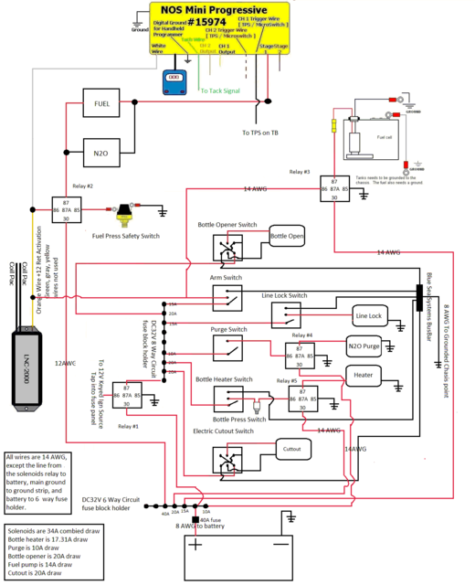
The stud labeled 2 is for the transbrake. Congratulations on purchasing your nos launcher progressive controller! Progressive wiring diagrams using controller and driver 5. Single stage nos system with transbrake interrupt relay, msd window switch, and dynotune delay timer. Two completely independent stages of nitrous/fuel control, each with independent throttle position activation switch and progressive ramps.
 Source: corvetteforum.com
Single stage nos system with transbrake interrupt (no relay), msd window switch, and dynotune delay timer. Wire, wire labels, crimp terminals, fuses, switches, and relays. It combines a tps sensing switch, two rpm window switches, and two progressive timers all into one unit. Single stage nos system with transbrake interrupt (no relay), msd window switch, and dynotune delay timer. Rev f blue tps wot input wire connection diagrams advanced programming options.
 Source: schematron.org
Nitrous wiring diagram with transbrake. To complete the installation, you will require: Single stage nos system with transbrake interrupt (no relay), msd window switch, and dynotune delay timer. The stud labeled 2 is for the transbrake. It features a black anodized, billet aluminum case and unique adjustment knobs that lock into place, so the progressive settings can�t accidentally be changed.
 Source: turbobullet.com
Single stage nos system with transbrake interrupt relay, msd window switch, and dynotune delay timer. It features a black anodized, billet aluminum case and unique adjustment knobs that lock into place, so the progressive settings can�t accidentally be changed. May be used with the most single stage nitrous systems. Progressive wiring diagrams using controller and driver 5. Wire, wire labels, crimp terminals, fuses, switches, and relays.

Not following the advice below may result in system damage or at worst serious engine damage. The stud labeled 2 is for the transbrake. Ramp time is adjustable from 0 to 4.5. See wiring diagrams for an example. Single stage nos system with transbrake interrupt (no relay), msd window switch, and dynotune delay timer.
This site is an open community for users to share their favorite wallpapers on the internet, all images or pictures in this website are for personal wallpaper use only, it is stricly prohibited to use this wallpaper for commercial purposes, if you are the author and find this image is shared without your permission, please kindly raise a DMCA report to Us.
If you find this site helpful, please support us by sharing this posts to your own social media accounts like Facebook, Instagram and so on or you can also bookmark this blog page with the title nos progressive controller wiring diagram by using Ctrl + D for devices a laptop with a Windows operating system or Command + D for laptops with an Apple operating system. If you use a smartphone, you can also use the drawer menu of the browser you are using. Whether it’s a Windows, Mac, iOS or Android operating system, you will still be able to bookmark this website.
Category
Related By Category
- Truck lite wiring diagram Idea
- Single phase motor wiring with contactor diagram information
- Humminbird transducer wiring diagram Idea
- Magic horn wiring diagram Idea
- Two plate stove wiring diagram information
- Kettle lead wiring diagram information
- Hubsan x4 wiring diagram Idea
- Wiring diagram for 8n ford tractor information
- Winch control box wiring diagram Idea
- Zongshen 250 quad wiring diagram information