Nmea 2000 power cable wiring diagram information
Home » Trending » Nmea 2000 power cable wiring diagram information
Your Nmea 2000 power cable wiring diagram images are ready in this website. Nmea 2000 power cable wiring diagram are a topic that is being searched for and liked by netizens now. You can Download the Nmea 2000 power cable wiring diagram files here. Find and Download all free photos and vectors.
If you’re looking for nmea 2000 power cable wiring diagram images information connected with to the nmea 2000 power cable wiring diagram topic, you have come to the right blog. Our site always provides you with hints for seeing the highest quality video and image content, please kindly hunt and find more informative video content and images that match your interests.
Nmea 2000 Power Cable Wiring Diagram. The drain wire shields the signal, power, I think i got this diagram right, and i think it’s important to understand if your boat might end up with more than a few nmea 2000 powered devices on its network.as discussed on monday, the popular ‘light’ (or micro) size nmea cables only contain 22 awg power (and data) wires.its well insulated power wires are apparently perfectly safe (despite some internecine. Nmea 2000 characteristics each backbone: Having multiple sources of power can create a potential for ground loops, if not wired correctly.
 Lowrance Nmea 2000 Network Diagram Wiring Site Resource From wiringdatabaseinfo.blogspot.com
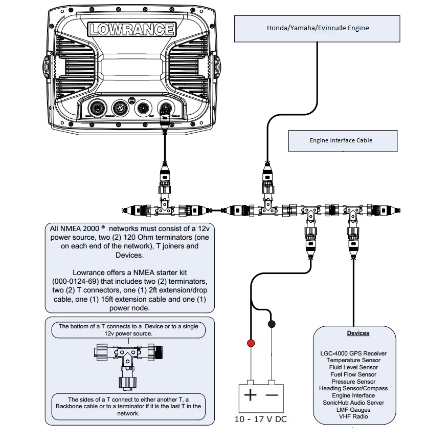
A diagram on the product box shows which nmea 2000 components are included. Nmea2000 starter kit consists of nmea2000 drop cable, 2m 1 ea. A twisted pair employing 22 awg stranded wire shall be used for the nmea 0183 data signals. The diagram below illustrates how an nmea 2000 network is put together: It reveals the parts of the circuit as simplified forms, as well as the power and signal connections in between the devices. A single network cable replaces a myriad of cables used by today’s methods of interconnection.
Furuno usa supplies nmea approved components as follows.
Having multiple sources of power can create a potential for ground loops, if not wired correctly. Interface cables shall be kept as short as possible and shall not exceed 150 feet. This eliminates the need to run a separate feed from a 12v breaker to. Foil (overall), foil (power pair), foil (data pair) power pair wire: A male or female seatalk ng to nmea 2000 drop cable: Include all of the devices you intend to connect to your network.
 Source: wiring121.blogspot.com
Pe (data wires), srpvc (power wires) construction: These diagrams are for the use of professional installers. Two signal wires, power and ground wires, and a drain wire. A twisted pair employing 22 awg stranded wire shall be used for the nmea 0183 data signals. It uses the high quality, nickel plated metal style connectors rather than the cheaper.

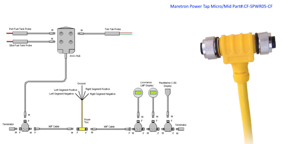
The nmea 2000 network accommodates navigation equipment, electrical power generation and distribution systems, engines and other machinery, piloting and steering systems, fire and other alarms, and controls. Two signal wires, power and ground wires, and a drain wire. The red wire from the sensor cable will be connected to the red wire from the nmea 2000 cable. These diagrams are for the use of professional installers. For my blue and grey networks, i am using nmea 2000 wiring components from maretron including double end cord sets available in blue and grey, and chose the “mid” size backbone for its larger diameter power wires that result in significantly reduced voltage drops vs.

These diagrams are for the use of professional installers. A quick guide to nmea 2000. The design provides two advantages. Likewise, the black wire from the sensor cable will be connected to. Two signal wires, power and ground wires, and a drain wire.
 Source: wiringdatabaseinfo.blogspot.com
Before attempting to rewire a transducer connector you should: I think i got this diagram right, and i think it�s important to understand if your boat might end up with more than a few nmea 2000 powered devices on its network. Actisense field fit connectors are available as straight or right angled options and in male and female variants to suit any installation requirement. (each connector has 3 holes to accommodate up to 3 wires.) note: A diagram on the product box shows which nmea 2000 components are included.
![[DIAGRAM] Uniden Nmea Cable Wiring Diagram FULL Version HD [DIAGRAM] Uniden Nmea Cable Wiring Diagram FULL Version HD](https://ezgiresortotel.netlify.app/img/placeholder.svg)
The nmea 2000 wiring colour system is standardised so the colours and pin numbers will be the same for any wire and connector combination that uses the same devicenet standard. Likewise, the black wire from the sensor cable will be connected to. Before attempting to rewire a transducer connector you should: If you do not have a nmea 2000 network installed on your boat, you will need the appropriate nmea 2000 cables and connectors to build one. A wiring diagram is a simplified conventional photographic depiction of an electric circuit.

As discussed on monday, the popular �light� (or micro) size nmea cables only contain 22 awg power (and data) wires. A male or female seatalk ng to nmea 2000 drop cable: It uses the high quality, nickel plated metal style connectors rather than the cheaper. Garmin displays may also include additional nmea 2000 components (such as a power cable). Two signal wires, power and ground wires, and a drain wire.

For my blue and grey networks, i am using nmea 2000 wiring components from maretron including double end cord sets available in blue and grey, and chose the “mid” size backbone for its larger diameter power wires that result in significantly reduced voltage drops vs. Furuno usa supplies nmea approved components as follows. The nmea 2000 components included with a garmin sensor or display are listed in the product. More importantly, the cable can include a sixth wire which allows for backward compatibility with seatalk 1. A quick guide to nmea 2000.
 Source: diagramresource.blogspot.com
Yes, gc needs to get the simnet to nmea 2000 cable you show in the link. A male or female seatalk ng to nmea 2000 drop cable: If you do not have a nmea 2000 network installed on your boat, you will need the appropriate nmea 2000 cables and connectors to build one. The nmea 2000 network accommodates navigation equipment, electrical power generation and distribution systems, engines and other machinery, piloting and steering systems, fire and other alarms, and controls. Check to see if an adapter cable exists (see the adapters page).
 Source: ricardolevinsmorales.com
The nmea 2000® cable system uses a trunk (sometimes referred to as the backbone) and drop line topology as shown in figure 1. 4x22 awg, 22 awg drain shielding (3 levels): These diagrams are for the use of professional installers. A male or female seatalk ng to nmea 2000 drop cable: Having multiple sources of power can create a potential for ground loops, if not wired correctly.
 Source: maretron.com
Include all of the devices you intend to connect to your network. Wiring diagram pinout to place garmin nuvi oregon and gpsmap 62 gps in recharge mode. Wiring diagram for lowrance nmea furthermore garmin new install no satellite signal also nmea wiring diagram for two screens. Two signal wires, power and ground wires, and a drain wire. Before attempting to rewire a transducer connector you should:
 Source: wiringall.com
Likewise, the black wire from the sensor cable will be connected to. Courtesy garmin power up the network. I think i got this diagram right, and i think it’s important to understand if your boat might end up with more than a few nmea 2000 powered devices on its network.as discussed on monday, the popular ‘light’ (or micro) size nmea cables only contain 22 awg power (and data) wires.its well insulated power wires are apparently perfectly safe (despite some internecine. Nmea2000 starter kit consists of nmea2000 drop cable, 2m 1 ea. Use this diagram to connect the lvr to a lowrance gps unit that is not connected to a radar unit.
 Source: ricardolevinsmorales.com
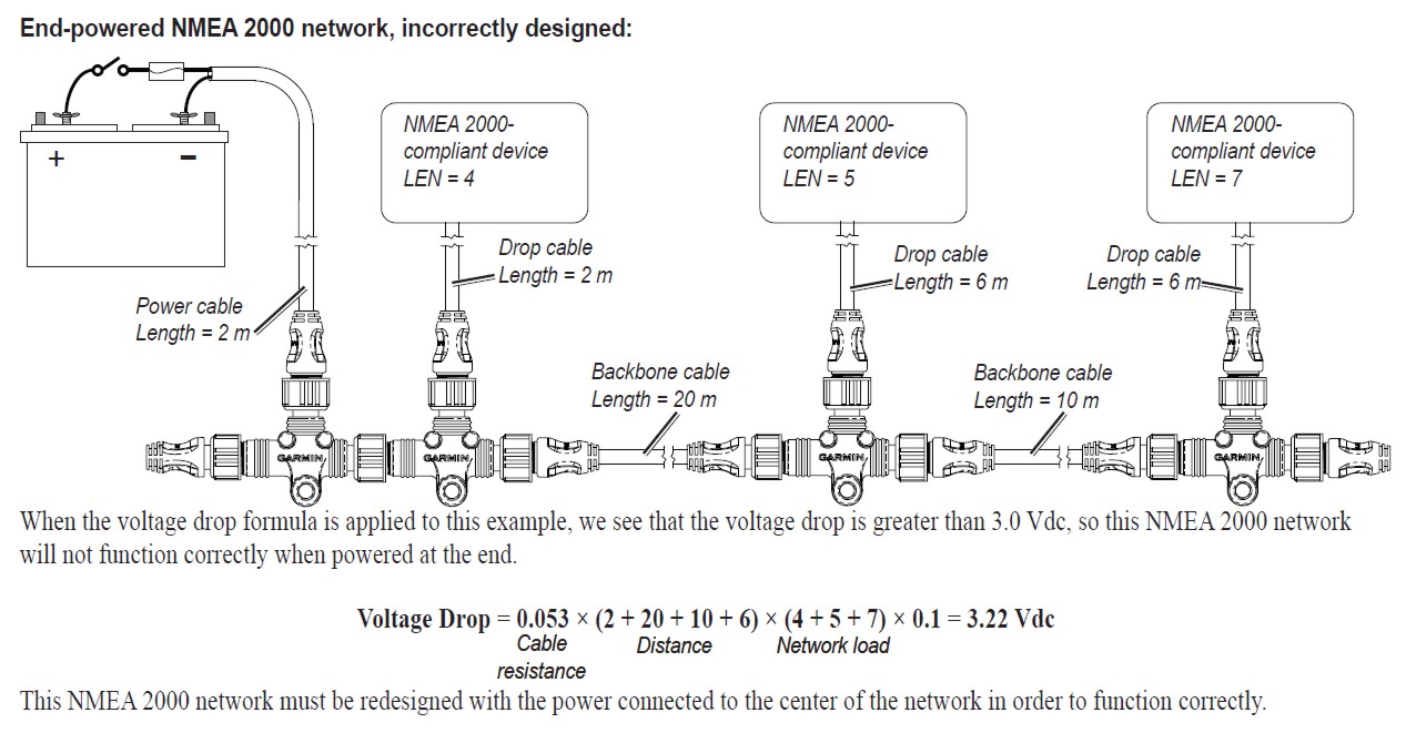
For my blue and grey networks, i am using nmea 2000 wiring components from maretron including double end cord sets available in blue and grey, and chose the “mid” size backbone for its larger diameter power wires that result in significantly reduced voltage drops vs. You can connect power either at the end of your nmea 2000 network or in the middle. Garmin displays may also include additional nmea 2000 components such as a power cable. The drain wire shields the signal, power, The red wire from the sensor cable will be connected to the red wire from the nmea 2000 cable.
 Source: peppiinapuoti.blogspot.com
Include all of the devices you intend to connect to your network. The more popular micro size. (each connector has 3 holes to accommodate up to 3 wires.) note: Having multiple sources of power can create a potential for ground loops, if not wired correctly. Furuno usa supplies nmea approved components as follows.

Yes, gc needs to get the simnet to nmea 2000 cable you show in the link. Garmin displays may also include additional nmea 2000 components such as a power cable. The nmea 2000 components included with a garmin sensor or display are listed in the product. (each connector has 3 holes to accommodate up to 3 wires.) note: The nmea 2000® cable system uses a trunk (sometimes referred to as the backbone) and drop line topology as shown in figure 1.
 Source: ebay.com
Nmea2000 power tee, micro f/f, 8m 1 ea. The nmea 2000 network accommodates navigation equipment, electrical power generation and distribution systems, engines and other machinery, piloting and steering systems, fire and other alarms, and controls. Having multiple sources of power can create a potential for ground loops, if not wired correctly. If you do not have a nmea 2000 network installed on your boat, you will need the appropriate nmea 2000 cables and connectors to build one. It uses the high quality, nickel plated metal style connectors rather than the cheaper.
 Source: galvinconanstuart.blogspot.com
If you do not have a nmea 2000 network installed on your boat, you will need the appropriate nmea 2000 cables and connectors to build one. Power cable and a separate nmea 2000 power cable. A connector is used for the upstream connection towards the host and b connector for the downward stream to the usb device. The nmea 2000 components included with a garmin sensor or display are listed in the product. A male or female seatalk ng to nmea 2000 drop cable:
 Source: thehulltruth.com
Nmea2000 backbone cable, 6m 1 ea. Interface cables shall be kept as short as possible and shall not exceed 150 feet. The nmea 2000® cable system includes five wires within a single waterproof cable: You can connect power either at the end of your nmea 2000 network or in the middle. I think i got this diagram right, and i think it�s important to understand if your boat might end up with more than a few nmea 2000 powered devices on its network.
 Source: digitalyacht.net
The design provides two advantages. The nmea 2000 wiring colour system is standardised so the colours and pin numbers will be the same for any wire and connector combination that uses the same devicenet standard. In this post, you can find out how to install a navlink2 nmea 2000 to wifi server on a digital yacht nmea 2000 network. It reveals the parts of the circuit as simplified forms, as well as the power and signal connections in between the devices. For my blue and grey networks, i am using nmea 2000 wiring components from maretron including double end cord sets available in blue and grey, and chose the “mid” size backbone for its larger diameter power wires that result in significantly reduced voltage drops vs.
This site is an open community for users to share their favorite wallpapers on the internet, all images or pictures in this website are for personal wallpaper use only, it is stricly prohibited to use this wallpaper for commercial purposes, if you are the author and find this image is shared without your permission, please kindly raise a DMCA report to Us.
If you find this site convienient, please support us by sharing this posts to your favorite social media accounts like Facebook, Instagram and so on or you can also save this blog page with the title nmea 2000 power cable wiring diagram by using Ctrl + D for devices a laptop with a Windows operating system or Command + D for laptops with an Apple operating system. If you use a smartphone, you can also use the drawer menu of the browser you are using. Whether it’s a Windows, Mac, iOS or Android operating system, you will still be able to bookmark this website.
Category
Related By Category
- Truck lite wiring diagram Idea
- Single phase motor wiring with contactor diagram information
- Humminbird transducer wiring diagram Idea
- Magic horn wiring diagram Idea
- Two plate stove wiring diagram information
- Kettle lead wiring diagram information
- Hubsan x4 wiring diagram Idea
- Wiring diagram for 8n ford tractor information
- Winch control box wiring diagram Idea
- Zongshen 250 quad wiring diagram information