Msd 8950 wiring diagram information
Home » Trending » Msd 8950 wiring diagram information
Your Msd 8950 wiring diagram images are ready. Msd 8950 wiring diagram are a topic that is being searched for and liked by netizens today. You can Get the Msd 8950 wiring diagram files here. Get all royalty-free images.
If you’re looking for msd 8950 wiring diagram images information linked to the msd 8950 wiring diagram keyword, you have visit the ideal blog. Our site always provides you with suggestions for seeing the highest quality video and picture content, please kindly hunt and locate more informative video articles and images that match your interests.
Msd 8950 Wiring Diagram. Conjunction with an rpm activated switch (such as. Msd rpm activated switch pn 8950. Then, i ran a bypass on the switch wire at the accelerator pedal. I would like to run two relays on the 8950 rpm activated switch, using the yellow (no) and gray (nc) lines.
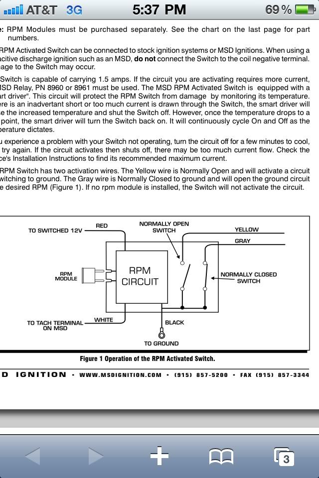 Msd 8950 Wiring Diagram From schematron.org
I want to wire a 8972 retard box and 8950 and wot micro switch and relay to solenoids and arming switch. So i got my new msd 8950 in today and connected everything right and still no vvl activation.i am bypassing the relay for now because i heard it is supposed to work but nothing is working thus far.here is how i have the msd 8950 wired to see if anyone can see anything that i�m doing wrong: The other wire on the shift solenoid hooks to chassis ground. Msd rpm activated switch pn 8950 important: There are many ways that the rpm switch may be installed. By comparing the engine s specifications against the chart, a usable timing guideline.
I want to wire a 8972 retard box and 8950 and wot micro switch and relay to solenoids and arming switch.
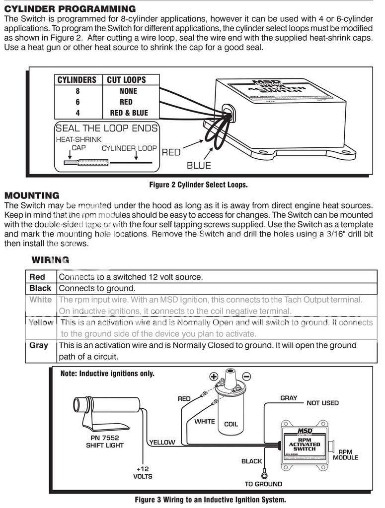
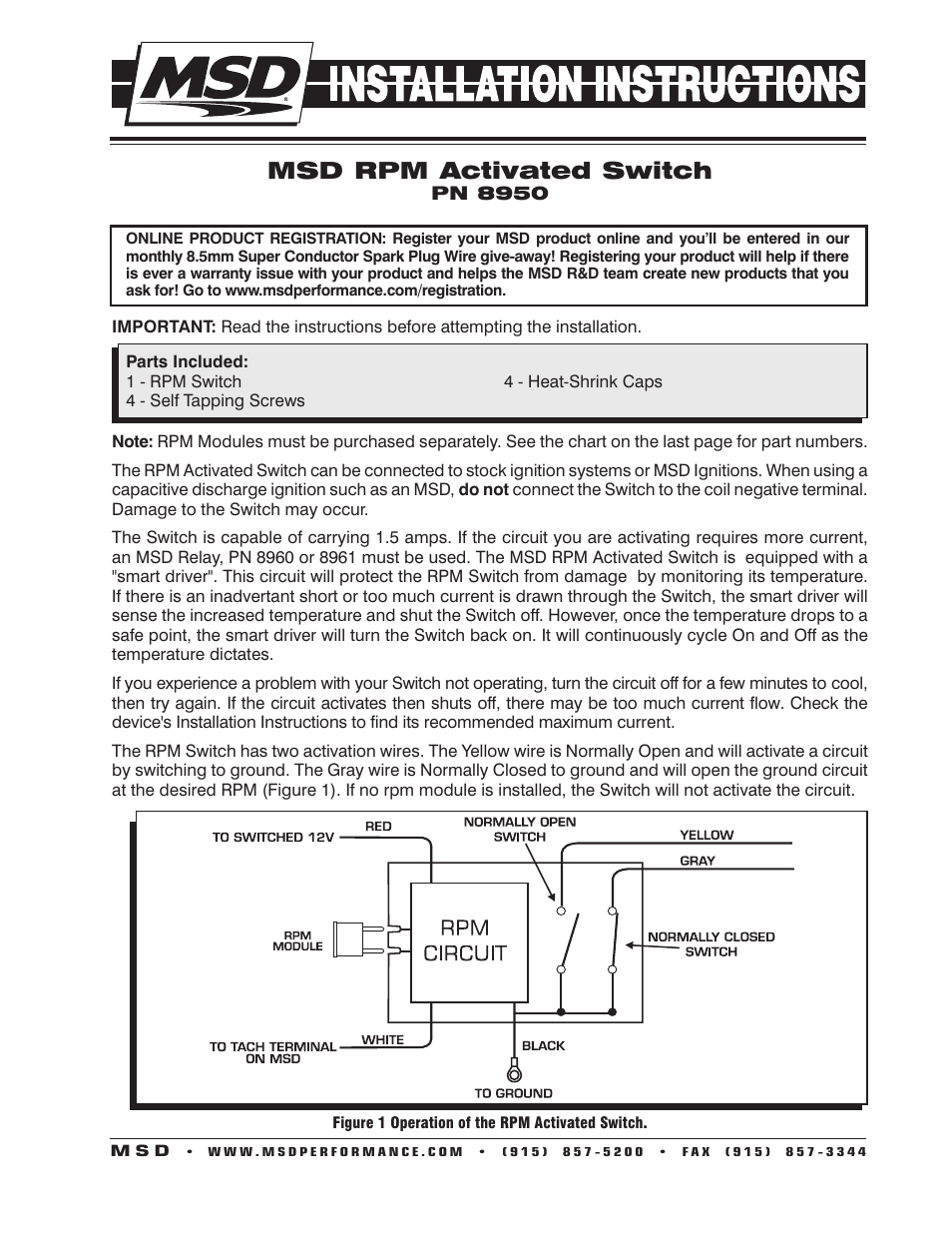
Read the instructions before attempting the installation. It will be capable to provide you with extra tools like. White the rpm input wire. In other words, the gray wire is grounded before the rpm chip is. I have an 89 mustang thats fuel injected. Autotronic controls corporation 1490 henry brennan dr., el paso, tx.

Read the instructions before attempting the the yellow wire is normally open and will activate a circuit. Use diagrams on page 3 for relay terminal #30 connection. I have an 89 mustang thats fuel injected. See the chart on the last page for part 8972 wiring diagram for newbie.
 Source: schematron.org
I added a shift light while i was doing this. Goin crazy with a shifnoid and msd rpm switch i wanted it nomally open energizing the 1) yellow wire from msd switch goes to 85 on relay.pdfファイルを閲覧・印刷するには、adobe reader. Read the instructions before attempting the installation. Read the instructions before attempting the the yellow wire is normally open and will activate a circuit. Install power properly and as safe as possible.

Repairing electrical wiring, greater than any other household project is about safety. Read online or download in pdf without registration. Connect post 30 to the solenoid. The different rpm modules are activated when 12 volts are applied to a corresponding wire. Msd rpm activated switch pn 8950.
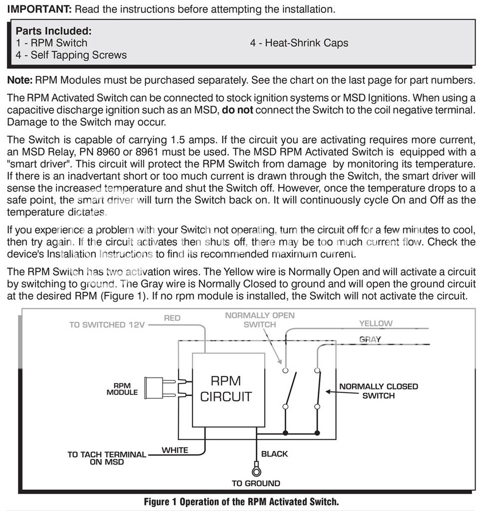 Source: ebay.com
6.0 — wiring diagrams page 3,4 7.0 — wiring msd 8950 rpm switch page 5 8.0 — optional products for efi motorcycles page 5 1.0 — general safety precautions this dry nitrous system is intended for fuel injected motorcycles only! Do you have a timing diagram for the yellow and gray wires once the chip rpm is reached? I want to wire a 8972 retard box and 8950 and wot micro switch and relay to solenoids and arming switch. One to ground a circuit and the other to open a circuit. Are the yellow and gray wires a make before brake connection or a brake before make connection.
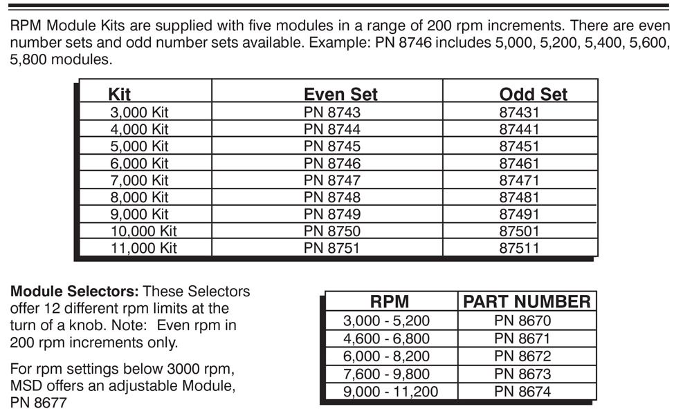 Source: ebay.com
Read online or download in pdf without registration. The other wire on the shift solenoid hooks to chassis ground. See the chart on the last page for part This helps keep tire temperatures consistent. Wiring diagram also provides beneficial suggestions for tasks which may demand some extra tools.
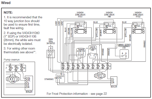 Source: schematron.org
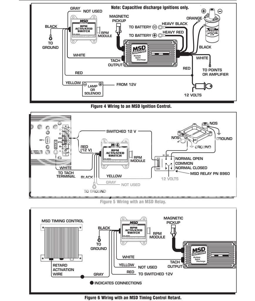
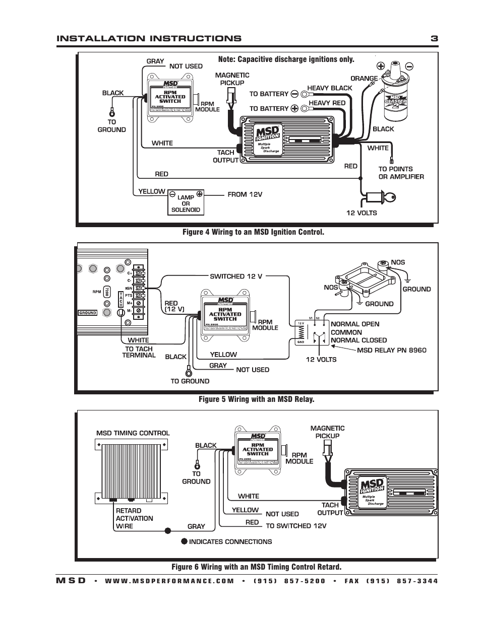
Figure 6 wiring with an msd timing control retard. Read the instructions before attempting the the yellow wire is normally open and will activate a circuit. C , you may need to change the terminals and boots of your wires. Connect it to the tach output terminal. 6.0 — wiring diagrams page 3,4 7.0 — wiring msd 8950 rpm switch page 5 8.0 — optional products for efi motorcycles page 5 1.0 — general safety precautions this dry nitrous system is intended for fuel injected motorcycles only!
 Source: ebay.com
By comparing the engine s specifications against the chart, a usable timing guideline. Read the instructions before attempting the installation. 30 goes to the shift solenoid. Wiring diagram also provides beneficial suggestions for tasks which may demand some extra tools. Msd rpm activated switch installation manuals and user guides for free.

Read the instructions before attempting the the yellow wire is normally open and will activate a circuit. Goin crazy with a shifnoid and msd rpm switch i wanted it nomally open energizing the 1) yellow wire from msd switch goes to 85 on relay.pdfファイルを閲覧・印刷するには、adobe reader. I have an 89 mustang thats fuel injected. Then, connect this ground wire to the yellow wire on the msd 8950 switch (normally open ground). So i got my new msd 8950 in today and connected everything right and still no vvl activation.i am bypassing the relay for now because i heard it is supposed to work but nothing is working thus far.here is how i have the msd 8950 wired to see if anyone can see anything that i�m doing wrong:
 Source: wiringall.com
There are many ways that the rpm switch may be installed. Wiring red connect to switched 12 volts black connect to ground green rpm input wire. A chart of module kits is listed at the end of these instructions. I want to wire a 8972 retard box and 8950 and wot micro switch and relay to solenoids and arming switch. By comparing the engine s specifications against the chart, a usable timing guideline.
 Source: scrapbookmamaw.blogspot.com
Install power properly and as safe as possible. In other words, the gray wire is grounded before the rpm chip is. (shifnoid or msd) use this diagram 87 87 85 85 30 30 86 86 interface relay interface relay shifnoid wiring diagram for a hurst quarter stick or a b&m pro stick with a sn5000fc or rc solenoid shift kit 87a 87a not used not used 1/4 inch gap 1/4 inch gap +12v to switched side of main battery disconnect switch +12v to switched side of main battery If this works,, my only thinking is that we statically pull the shift solenoid into shift. It will be capable to provide you with extra tools like.
 Source: schematron.org
+12v in on 85 & 86 (tied together) yellow trigger wire from the msd rpm switch to 87. Never connect any wires to the coil terminals when an msd 6, 7, 8 or 10 series ignition is installed. Then, i ran a bypass on the switch wire at the accelerator pedal. Wiring the unit follow the wiring diagram supplied. Msd rpm activated switch installation manuals and user guides for free.
 Source: ebay.com
The installer needs to set rpm switch to proper rpm and test operation. There are many ways that the rpm switch may be installed. I have a 6al box wired to the car now. The tach signal typically comes from the negative coil wire. +12v in on 85 & 86 (tied together) yellow trigger wire from the msd rpm switch to 87.
 Source: wiringdiagramharnessideas.blogspot.com
Install power properly and as safe as possible. There are many ways that the rpm switch may be installed. With an msd ignition, this connects to the tach output terminal. This helps keep tire temperatures consistent. See the chart on the last page for part
 Source: holley.com
That is why we have assembled the msd ignition wiring diagrams and tech notes. Then, i ran a bypass on the switch wire at the accelerator pedal. Msd rpm activated switch pn 8950 important: It will be capable to provide you with extra tools like. White the rpm input wire.
 Source: skippingtheinbetween.blogspot.com
Read the instructions before attempting the the yellow wire is normally open and will activate a circuit. Conjunction with an rpm activated switch (such as. Figure 6 wiring with an msd timing control retard. Then connect the msd switche�s power, ground, and tach signal wires. 30 goes to the shift solenoid.
 Source: manualsdir.com
Msd rpm activated switch pn 8950 important: White wire to blue dist. With this switch, when the engine reaches the desired rpm, the high speed retard will be activated (figure 6). I want to use the 8950 as a cut off if i miss a shift. Then connect the msd switche�s power, ground, and tach signal wires.
 Source: manualsdir.com
Msd shift light pn 8952 parts included: Msd shift light pn 8952 parts included: White wire to blue dist. Repairing electrical wiring, greater than any other household project is about safety. Msd rpm activated switch pn 8950 important:
 Source: speedwaymotors.com
+12v in on 85 & 86 (tied together) yellow trigger wire from the msd rpm switch to 87. Do you have a timing diagram for the yellow and gray wires once the chip rpm is reached? Read online or download in pdf without registration. Yellow connects to the white wire of the msd magnetic pickup connector: If this works,, my only thinking is that we statically pull the shift solenoid into shift.
This site is an open community for users to do sharing their favorite wallpapers on the internet, all images or pictures in this website are for personal wallpaper use only, it is stricly prohibited to use this wallpaper for commercial purposes, if you are the author and find this image is shared without your permission, please kindly raise a DMCA report to Us.
If you find this site value, please support us by sharing this posts to your preference social media accounts like Facebook, Instagram and so on or you can also save this blog page with the title msd 8950 wiring diagram by using Ctrl + D for devices a laptop with a Windows operating system or Command + D for laptops with an Apple operating system. If you use a smartphone, you can also use the drawer menu of the browser you are using. Whether it’s a Windows, Mac, iOS or Android operating system, you will still be able to bookmark this website.
Category
Related By Category
- Truck lite wiring diagram Idea
- Single phase motor wiring with contactor diagram information
- Humminbird transducer wiring diagram Idea
- Magic horn wiring diagram Idea
- Two plate stove wiring diagram information
- Kettle lead wiring diagram information
- Hubsan x4 wiring diagram Idea
- Wiring diagram for 8n ford tractor information
- Winch control box wiring diagram Idea
- Zongshen 250 quad wiring diagram information