Msd 6520 wiring diagram information
Home » Trending » Msd 6520 wiring diagram information
Your Msd 6520 wiring diagram images are available in this site. Msd 6520 wiring diagram are a topic that is being searched for and liked by netizens today. You can Find and Download the Msd 6520 wiring diagram files here. Get all royalty-free photos and vectors.
If you’re looking for msd 6520 wiring diagram pictures information related to the msd 6520 wiring diagram topic, you have visit the ideal blog. Our site frequently provides you with hints for seeking the highest quality video and picture content, please kindly hunt and locate more enlightening video content and images that fit your interests.
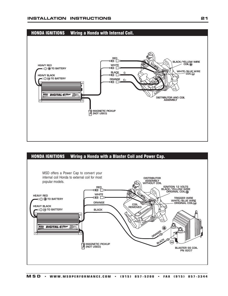
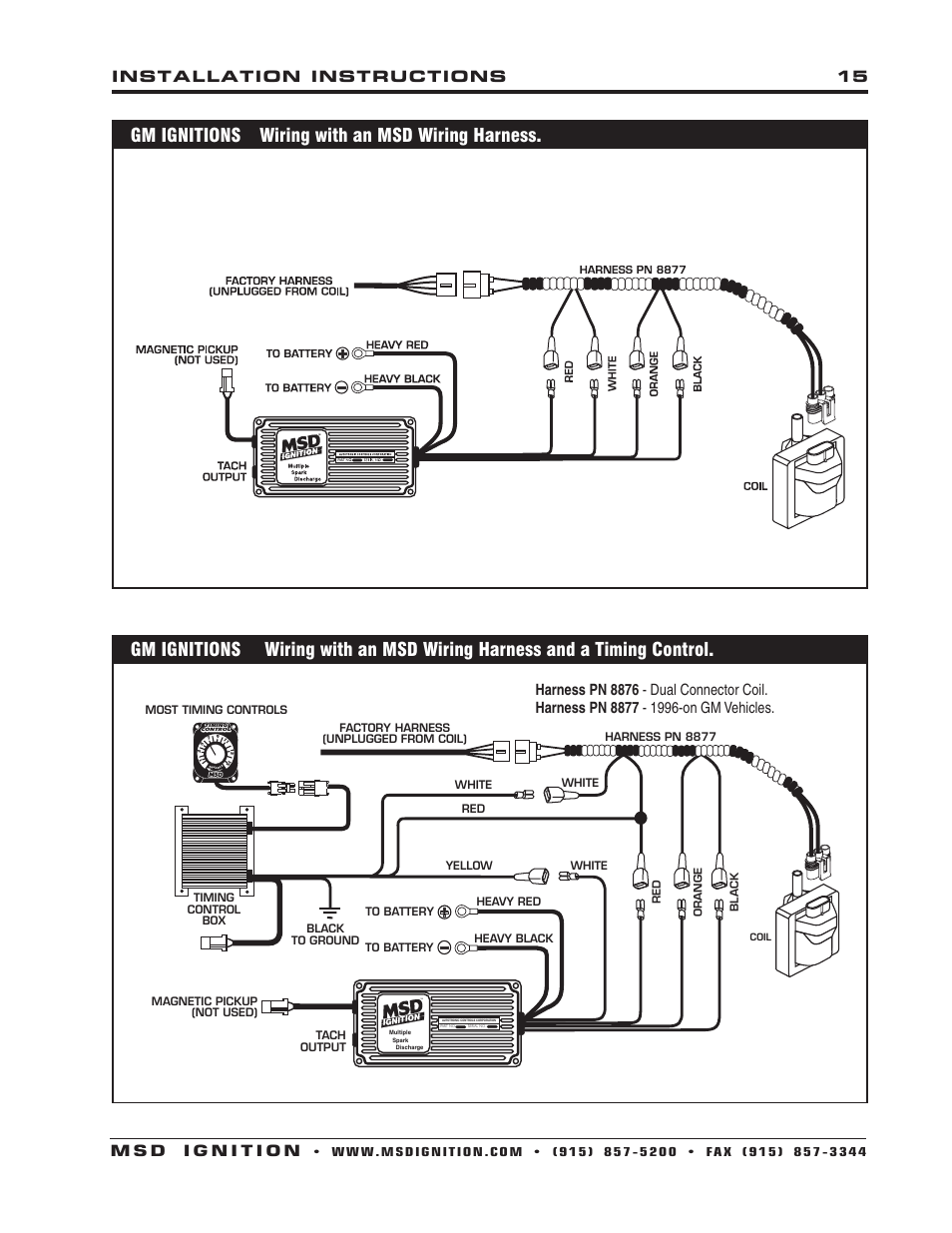
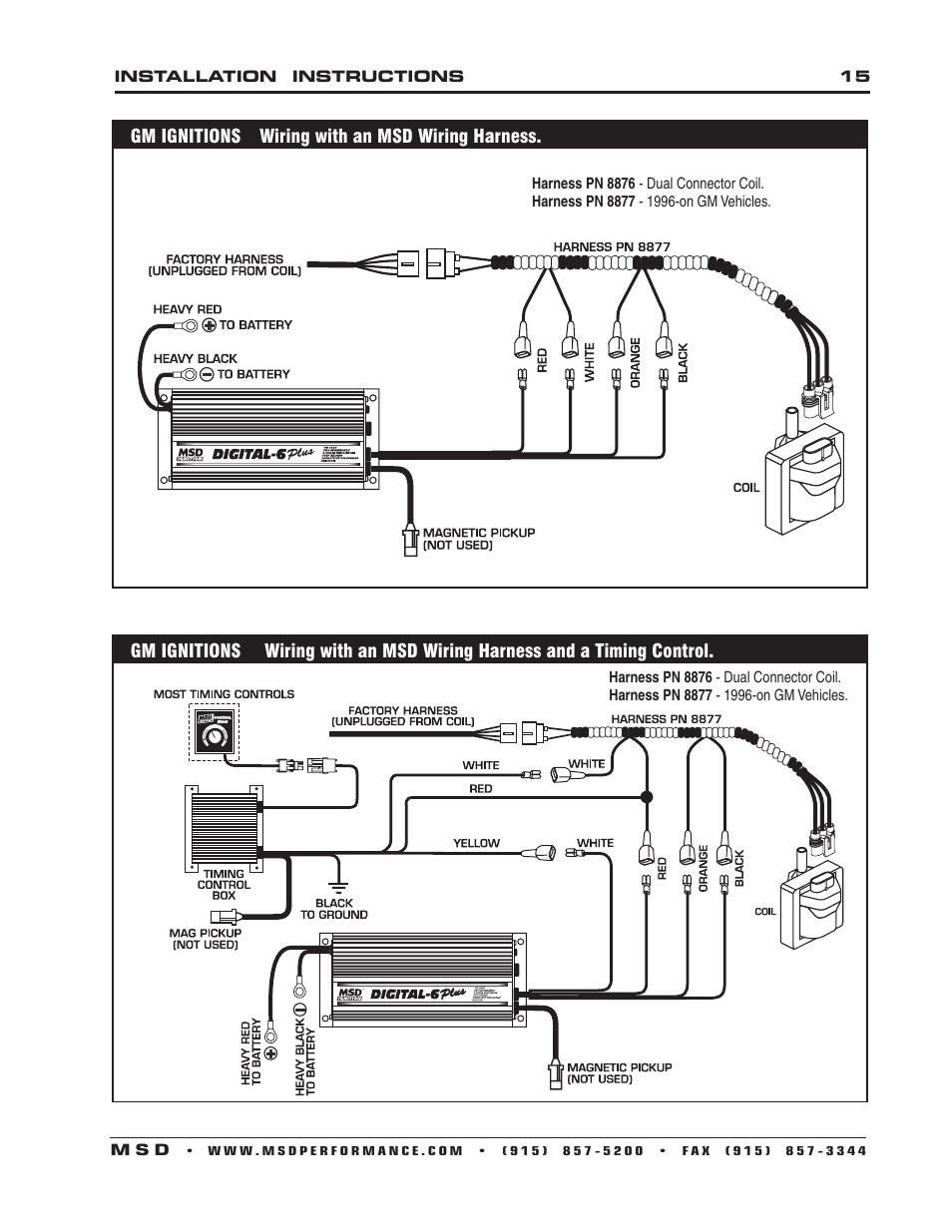
Msd 6520 Wiring Diagram. Harness pn 8877 1996 on gm vehicles. Autotronic controls corporation 1490 henry brennan dr el paso texas 79936 915 857 5200 fax. Solid core spark plug wires cannot be used with an msd ignition. During installation, disconnect the battery cables.
 Msd 6520 Wiring Diagram From diagramweb.net
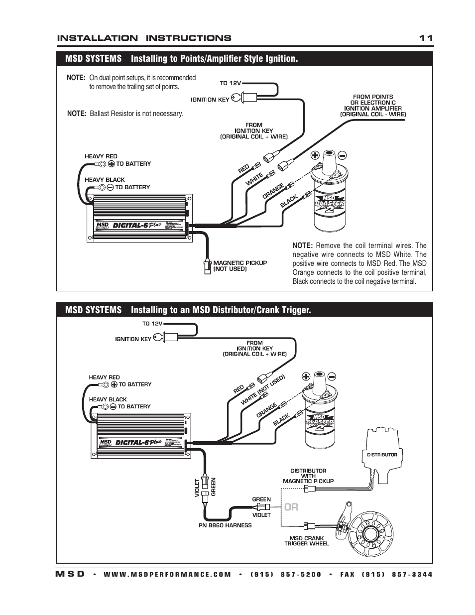
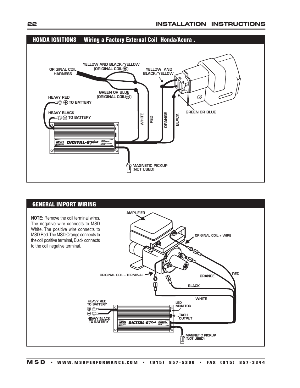
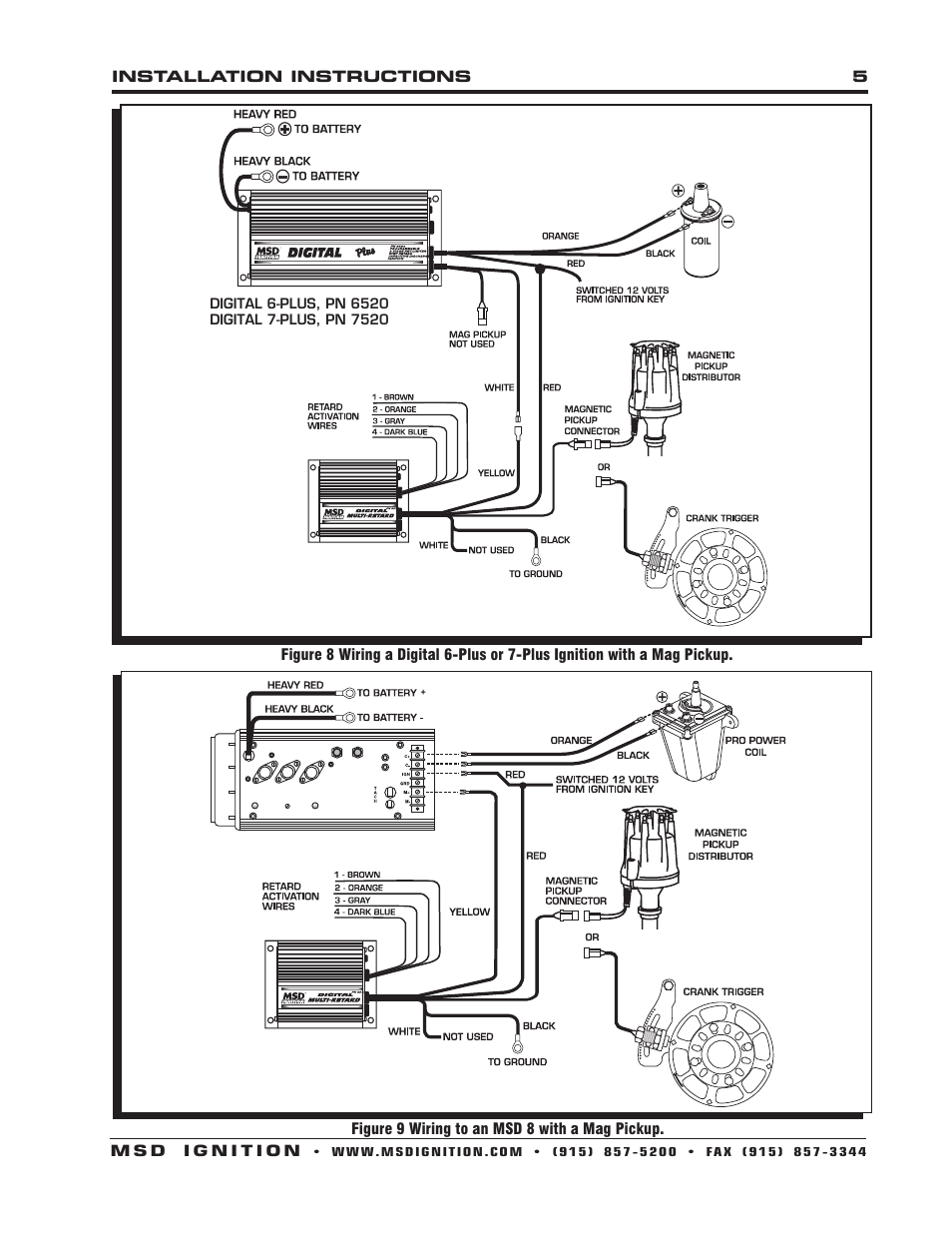
Figure 4 wiring to an msd ignition control. With a msd modules, the ignition module wires you need to know about are: This wire connects to the coil positive (+) terminal. Wiring diagram also provides beneficial suggestions for projects which may need some extra gear. Power is a heavy red wire, ; Solid core spark plug wires cannot be used with an msd ignition.
Digital 6 plus ignition note:
Wiring diagram also offers beneficial ideas for assignments which may demand some added tools. So if your car is efi with either the stock tfi dizzy or the msd replacement tfi dizzy leave the loop connected. Digital 6 plus ignition note: Wiring diagram also provides beneficial suggestions for projects which may need some extra gear. Msd digital 6 plus ignition control, pn parts included: (shifnoid or msd) use this diagram 87 87 85 85 30 30 86 86 interface relay interface relay shifnoid wiring diagram for a hurst quarter stick or a b&m pro stick with a sn5000fc or rc solenoid shift kit 87a 87a not used not used 1/4 inch gap 1/4 inch gap +12v to switched side of main battery disconnect switch +12v to switched side of main battery
 Source: funnyhacklife.blogspot.com
Msd digital 6 plus ignition control, pn parts included: Whirlpool cabrio dryer parts diagram; Msd 6520 installation instruction pdf download. Msd ignition 6al 6420 wiring diagram free wiring diagram. Wiring diagram 30 amp generator plug best 30 amp twist lock plug.
 Source: manualsdir.com
Whirlpool cabrio dryer parts diagram; Otherwise, the arrangement won’t work as it ought to be. A pinout and wiring diagram for 120 240v generator outlet and plug l14 30. Nissan sr20 1992 tps wiring diagram; If not, the arrangement won’t work as it ought to be.
 Source: diagramweb.net
If not, the arrangement won’t work as it ought to be. #10 · mar 15, 2009. View and download msd installation instruction online. Advance control signal is a white wire, ; Solid core spark plug wires cannot be used with an msd ignition.
 Source: diagramweb.net
View and download msd installation instruction online. Harness pn 8877 1996 on gm vehicles. If not, the arrangement won’t work as it ought to be. So if your car is efi with either the stock tfi dizzy or the msd replacement tfi dizzy leave the loop connected. Figure 5 wiring with an msd relay.
 Source: ebay.ca
Nissan sr20 1992 tps wiring diagram; This can be beneficial for both the individuals and for specialists who’re looking to find out. This wire connects to the coil positive (+) terminal. If you are using a 50 output on your generator you will need a 50 amp breaker 50 amp power inlet box a 50 amp extension cable and 8 gauge wire. Wiring the msd 6a module.
 Source: tonetastic.info
That is why we have assembled the msd ignition wiring diagrams and tech notes. Wiring diagram also provides beneficial suggestions for projects which may need some extra gear. That is why we have assembled the msd ignition wiring diagrams and tech notes. Harness pn 8877 1996 on gm vehicles. Msd 60143 instruction manual and user guide mans io.
Source: cars-trucks24.blogspot.com
Wiring the msd 6a module. If you follow these instructions you can set the ignition configuration as follows: Digital 6 plus ignition note: Solid core spark plug wires cannot be used with an msd ignition. Each part should be placed and connected with different parts in specific manner.
![[DIAGRAM] Race Car Wiring Diagram Msd FULL Version HD [DIAGRAM] Race Car Wiring Diagram Msd FULL Version HD](http://www.manualsdir.com/manuals/256505/18/msd-6520-digital-6-plus-ignition-control-installation-page18.png) Source: sports-scoreboard-network.cisgabon.fr
Source: sports-scoreboard-network.cisgabon.fr
This guide even consists of suggestions for added provides that you might need to be able to end your tasks. That is the answer i got directly from msd tech line when i put my digital 6 in my car 5 years ago. These are instruction for an msd 6520 digital 6 box. This can be beneficial for both the individuals and for specialists who’re looking to find out. I have a 1972 oldsmobile cutlass supreme with an msd blaster coil #8252, and an msd distributor #8566, and of course the ignition controller as mentioned above.
 Source: wiringview.co
View and download msd installation instruction online. Solid core spark plug wires cannot be used with an msd ignition. Advance control signal is a white wire, ; This guide even consists of suggestions for added provides that you might need to be able to end your tasks. Digital 6 plus ignition note:
 Source: schematron.org
Tach signal is a yellow wire (do not use this to feed to pin #24 on megasquirt ® efi controller, it is for a tachometer only), ; Advance control signal is a white wire, ; Ground is a heavy black wire,; I have an issue with wiring my ignition control #6520, and i need some expert advice. Harness pn 8877 1996 on gm vehicles.
 Source: manualsdir.com
Connects to a switched 12 volt source such as the ignition key or switch. That is the answer i got directly from msd tech line when i put my digital 6 in my car 5 years ago. Figure 5 wiring with an msd relay. I have a 1972 oldsmobile cutlass supreme with an msd blaster coil #8252, and an msd distributor #8566, and of course the ignition controller as mentioned above. Wiring diagram also provides beneficial suggestions for projects which may need some extra gear.
Source: wiring121.blogspot.com
Msd 6520 digital 6 plus ignition & coil wiring help. Observe the recommendations for sensor returns (grounding). Digital 6 plus ignition note: Mount the coil on the motor, not on the firewall. Digital 6 plus ignition note:
 Source: diagramweb.net
This wire is responsible for turning the msd on and off. Msd 6520 installation instruction pdf download. Advance control signal is a white wire, ; Connects to a switched 12 volt source such as the ignition key or switch. Switched 12 volts is a thin red wire,
 Source: manualsdir.com
With a msd modules, the ignition module wires you need to know about are: Connects to a switched 12 volt source such as the ignition key or switch. View and download msd installation instruction online. Msd 6520 digital 6 plus ignition & coil wiring help. This wire connects to the coil positive (+) terminal.
 Source: manualsdir.com
Digital 6 plus ignition note: Ground is a heavy black wire,; Nissan sr20 1992 tps wiring diagram; Wiring diagram also provides beneficial suggestions for projects which may need some extra gear. When disconnecting the battery always remove the negative cable first and install it last.
 Source: manualsdir.com
That is why we have assembled the msd ignition wiring diagrams and tech notes. Solid core spark plug wires cannot be used with an msd ignition. Msd digital 6 plus ignition control, pn parts included: Solid core spark plug wires cannot be used with an msd ignition. Digital 6 plus ignition note:
 Source: annawiringdiagram.com
#10 · mar 15, 2009. Msd digital 6 plus ignition control, pn 6520 parts included: If you follow these instructions you can set the ignition configuration as follows: Solid core spark plug wires cannot be used with an msd ignition. To lengthen the wires, use one size bigger gauge wire (10 gauge for
 Source: tonetastic.info
Wiring the msd 6a module. That is why we have assembled the msd ignition wiring diagrams and tech notes. (shifnoid or msd) use this diagram 87 87 85 85 30 30 86 86 interface relay interface relay shifnoid wiring diagram for a hurst quarter stick or a b&m pro stick with a sn5000fc or rc solenoid shift kit 87a 87a not used not used 1/4 inch gap 1/4 inch gap +12v to switched side of main battery disconnect switch +12v to switched side of main battery So if your car is efi with either the stock tfi dizzy or the msd replacement tfi dizzy leave the loop connected. Figure 4 wiring to an msd ignition control.
This site is an open community for users to share their favorite wallpapers on the internet, all images or pictures in this website are for personal wallpaper use only, it is stricly prohibited to use this wallpaper for commercial purposes, if you are the author and find this image is shared without your permission, please kindly raise a DMCA report to Us.
If you find this site beneficial, please support us by sharing this posts to your own social media accounts like Facebook, Instagram and so on or you can also bookmark this blog page with the title msd 6520 wiring diagram by using Ctrl + D for devices a laptop with a Windows operating system or Command + D for laptops with an Apple operating system. If you use a smartphone, you can also use the drawer menu of the browser you are using. Whether it’s a Windows, Mac, iOS or Android operating system, you will still be able to bookmark this website.
Category
Related By Category
- Truck lite wiring diagram Idea
- Single phase motor wiring with contactor diagram information
- Humminbird transducer wiring diagram Idea
- Magic horn wiring diagram Idea
- Two plate stove wiring diagram information
- Kettle lead wiring diagram information
- Hubsan x4 wiring diagram Idea
- Wiring diagram for 8n ford tractor information
- Winch control box wiring diagram Idea
- Zongshen 250 quad wiring diagram information