Ms2 wiring diagram information
Home » Trending » Ms2 wiring diagram information
Your Ms2 wiring diagram images are ready. Ms2 wiring diagram are a topic that is being searched for and liked by netizens now. You can Get the Ms2 wiring diagram files here. Find and Download all royalty-free vectors.
If you’re looking for ms2 wiring diagram pictures information linked to the ms2 wiring diagram keyword, you have visit the right site. Our site frequently gives you suggestions for seeking the maximum quality video and image content, please kindly surf and locate more informative video articles and graphics that match your interests.
Ms2 Wiring Diagram. Marshall ms 2 circuit diagram html wiring diagram will come with numerous easy to follow marshall ms 2 circuit diagram html wiring diagram directions. 10� megasquirt electronic fuel injection wiring harness (ms1 / ms2 within megasquirt 2 wiring diagram. Ms1 + ms2 launch control wiring; This version of the documentation applies to:

This wiring arrangement can turn on or off lamps irrespective of their individual switch positions. • ms2 on v3.0 or v3.57 mainboard; However if you do have 3.57 it will have an additional db15 connector for extra inputs/outputs. The normally closed terminals of the fault signalling contacts are connected to the undervoltage release coil of the circuit breaker. Ms1 + ms2 programmable output wiring; If you have put your megasquirt ® together, but it does not work, don�t panic, just follow the troubleshooting instructions.
Ms2 + ms3 stepper motor idle valve options;
• microsquirt v3 as shown above running firmware ms2/extra 3.3.x does not apply to other megasquirt products or other firmware versions. • ms2 on v3.0 or v3.57 mainboard; • microsquirt v3 as shown above running firmware ms2/extra 3.3.x does not apply to other megasquirt products or other firmware versions. This wiring arrangement can turn on or off lamps irrespective of their individual switch positions. Click the wiring diagram image for a larger view note: And the t wave, which represents the.
 Source: miataturbo.net
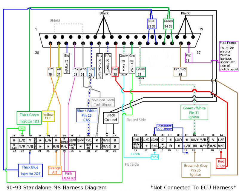
Integration with megasquirt and microsquirt ecus using can is available to reduce wiring by sharing sensors. Click the wiring diagram image for a larger view note: Mazda miata wiring diagrams 1990 to 1994 rusefi wiki engine diagram mx 5 forum standalone 1 6 96 for ls help the ms2 turbo 1996 m edition nb comboswitch 8 maf Click the image for a large wiring diagram. This version of the documentation applies to:
 Source: forums.vwvortex.com
Averaging 0 to 240 s, 2.5 hz sample rate, 1.5 to 228 s for 95% step change. The following are additional ones that are not available within those pdfs. Marshall ms 2 circuit diagram html wiring diagram will come with numerous easy to follow marshall ms 2 circuit diagram html wiring diagram directions. Here are the main application specific wiring details to keep in mind. If you are using the wiring harness then you are wiring everything directly back to.
 Source: aaroncake.net
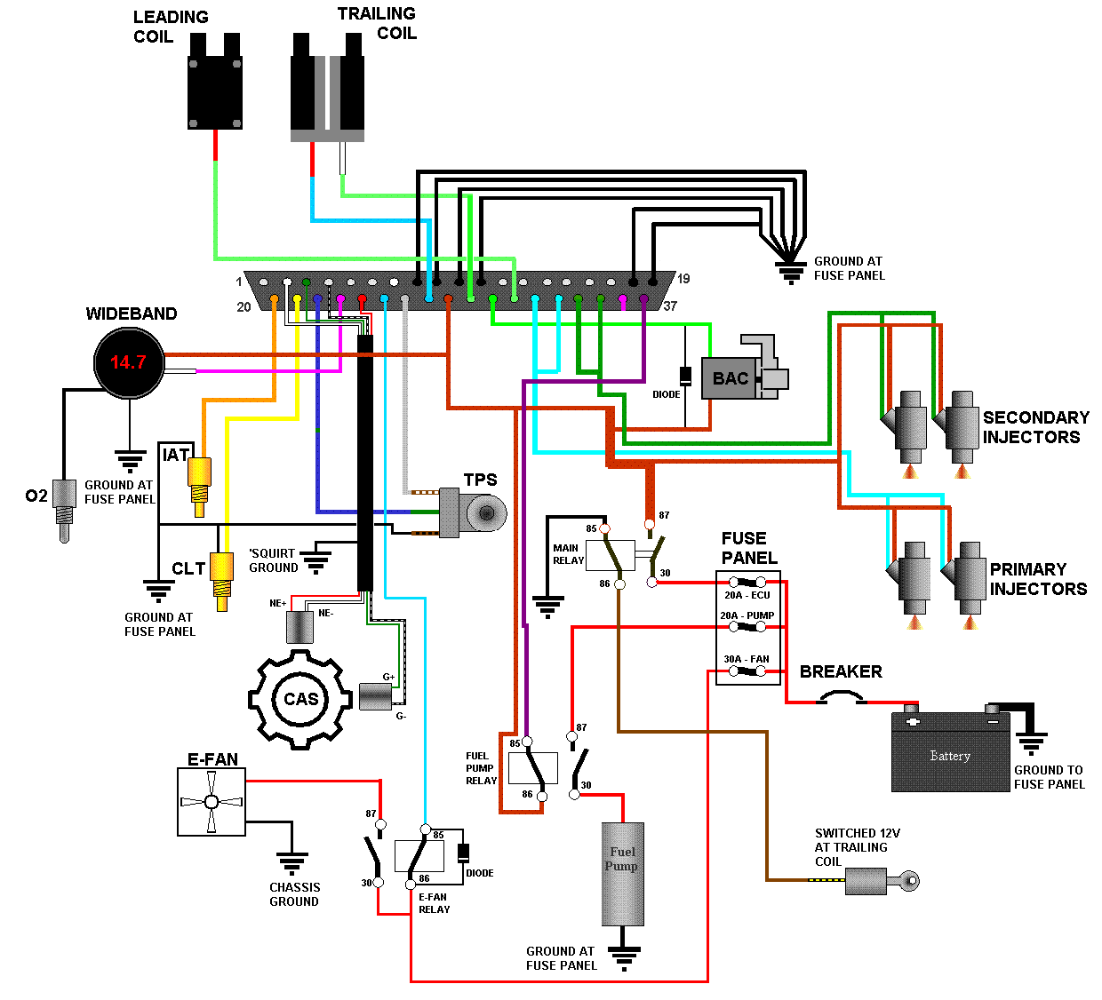
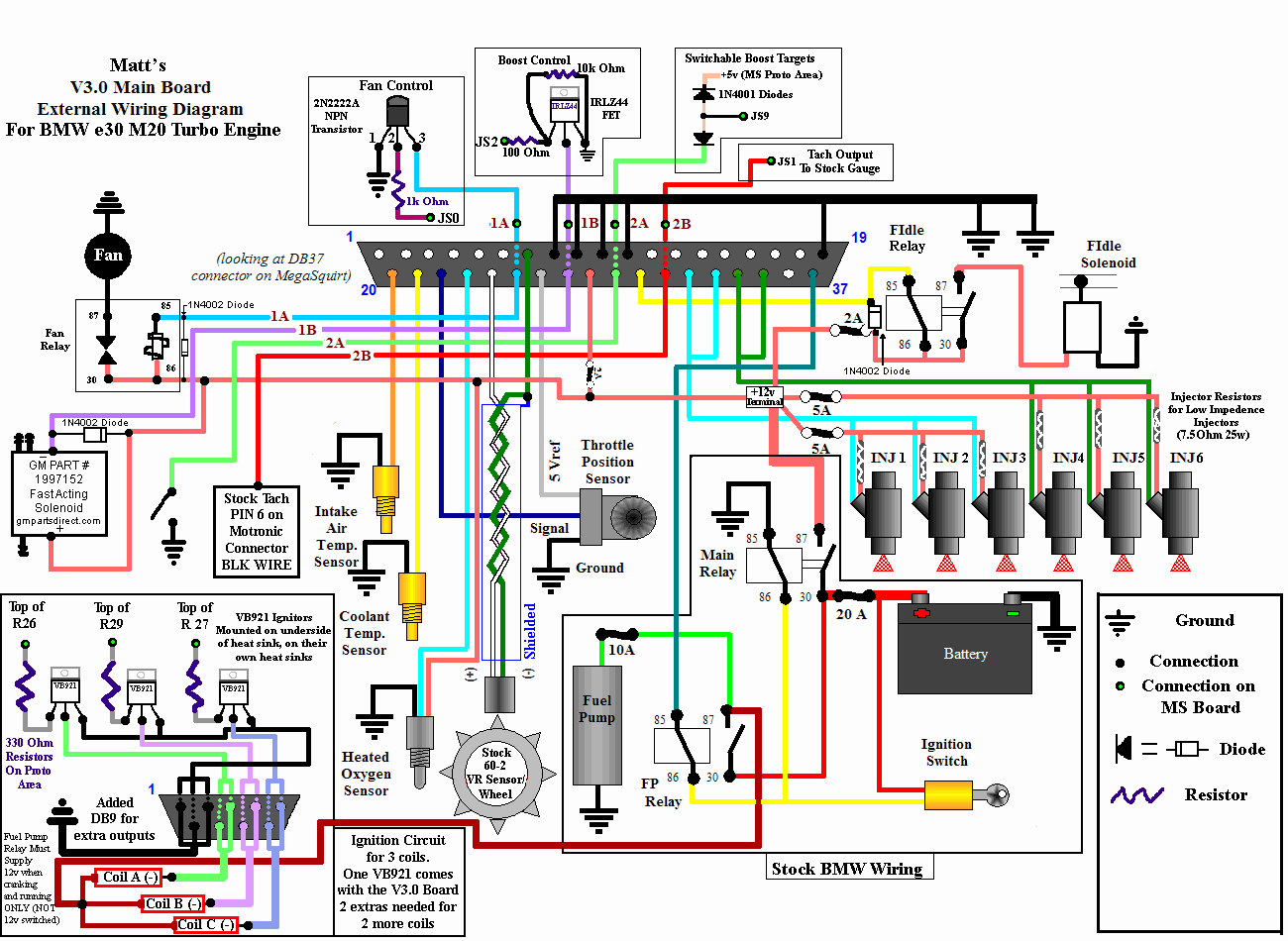
Also keep in mind wiring diagrams out there are good to follow however, there are some different ones. And the t wave, which represents the. Ford f150 tail light wiring diagram; To see all graphics within megasquirt 2 wiring diagram photographs gallery you need to comply with this particular website link. External wiring with a v3.0 main board.
 Source: wiring121.blogspot.com
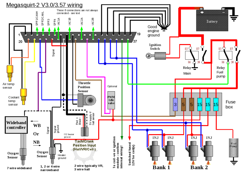
However if you do have 3.57 it will have an additional db15 connector for extra inputs/outputs. The wiring is the same for 3.0 and 3.57 boards all the pin outs are the same on db37. However if you do have 3.57 it will have an additional db15 connector for extra inputs/outputs. Ms2 + ms3 stepper motor idle valve options; The p wave, which represents the depolarization of the atria;
 Source: migweb.co.uk
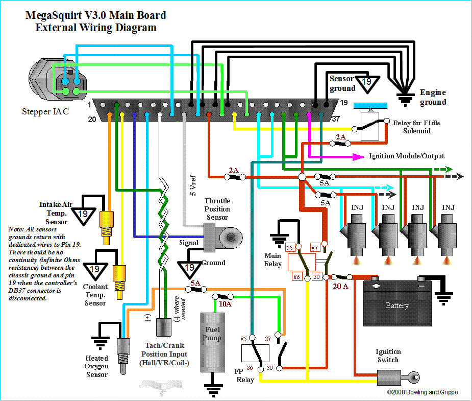
I do not see any wiring diagrams for ms2 that show distributor, coil and igniter. Mercury tilt and trim gauge wiring diagram; Ground is a heavy black wire,; 10� megasquirt electronic fuel injection wiring harness (ms1 / ms2 within megasquirt 2 wiring diagram, image size 1074 x 730 px, and to view image details please click the image. Power is a heavy red wire, ;
 Source: pinterest.com
Microsquirt has a flexible triggering input it can be triggered from a distributor or a multi tooth crankwheel. This makes explaining the code a bit easier. For any wiring diagram, it is critical to know how the board was built before figuring out the wiring diagram. 0 to 1250 ω max; If you have put your megasquirt ® together, but it does not work, don�t panic, just follow the troubleshooting instructions.
 Source: msextra.com
• products derived from the microsquirt module (e.g., diypnp and mspnp2). Megasquirt 2 wiring diagram regarding warm. This is pretty standard for any vehicle. If you have put your megasquirt ® together, but it does not work, don�t panic, just follow the troubleshooting instructions. Wiring diagram for bt openreach master socket 5c

This makes explaining the code a bit easier. Averaging 0 to 240 s, 2.5 hz sample rate, 1.5 to 228 s for 95% step change. The qrs complex, which represents the depolarization of the ventricles; Wiring diagram for bt openreach master socket 5c This makes explaining the code a bit easier.

Ms1 + ms2 knock input; Tach signal is a yellow wire (do not use this to feed to pin #24 on megasquirt ® efi controller, it is for a tachometer only), ; Col1 here is a wiring diagram which you can download and print. So i am not sure on which connection to make on the board since : Here are the main application specific wiring details to keep in mind.
 Source: diagramweb.net
Most schematics are provided in the hardware manual for your product. For megasquirt ii (as for most other ignition systems), the total ignition advance is based on three factors: This circuit is the same as the master on circuit the only change is an additional master switch (ms2) which is added to the phase line that was previously connected directly to the terminals of switches s1 to s4. 0 to 1250 ω max; Marshall ms 2 circuit diagram html wiring diagram will come with numerous easy to follow marshall ms 2 circuit diagram html wiring diagram directions.
 Source: aaroncake.net
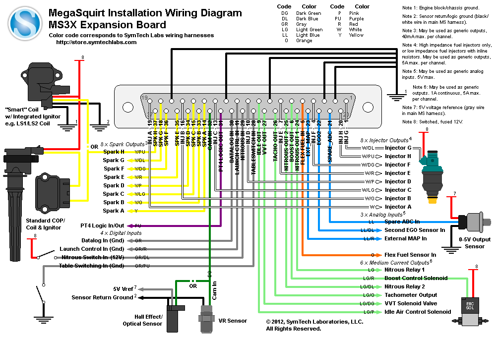
Note that injector wiring specifics are in the injectors & fuel supply section. Hardware manual covering specific wiring and configuration of your v mainboard with ms3x as shown above running firmware ms3 x. Also keep in mind wiring diagrams out there are good to follow however, there are some different ones. Ms1 + ms2 shift led/warning led; 10� megasquirt electronic fuel injection wiring harness (ms1 / ms2 within megasquirt 2 wiring diagram, image size 1074 x 730 px, and to view image details please click the image.
 Source: msextra.com
This version of the documentation applies to: This is a quick video going over the basic wiring of a megasquirt ecu into my z turbo build. Most schematics are provided in the hardware manual for your product. However if you do have 3.57 it will have an additional db15 connector for extra inputs/outputs. Rv park electrical wiring diagrams;
 Source: msextra.com
Microsquirt has a flexible triggering input it can be triggered from a distributor or a multi tooth crankwheel. Ford f150 tail light wiring diagram; Also keep in mind wiring diagrams out there are good to follow however, there are some different ones. Averaging 0 to 240 s, 2.5 hz sample rate, 1.5 to 228 s for 95% step change. 10� megasquirt electronic fuel injection wiring harness (ms1 / ms2 within megasquirt 2 wiring diagram.
 Source: forums.hybridz.org
• ms2 on a v3.0 mainboard as shown above running firmware ms2/extra 3.3.x does not apply to other megasquirt products or other firmware versions. Ground is a heavy black wire,; The wiring diagram/schematic above shows you how to connect the a4899 driver to a. So i am not sure on which connection to make on the board since : • ms2 on a v3.0 mainboard as shown above running firmware ms2/extra 3.3.x does not apply to other megasquirt products or other firmware versions.
 Source: forums.hybridz.org
See the ignition hardware manual for details on controlling different ignition systems and the diy options for multiple spark outputs. 10� megasquirt electronic fuel injection wiring harness (ms1 / ms2 within megasquirt 2 wiring diagram, image size 1074 x 730 px, and to view image details please click the image. Ms1 + ms2 programmable output wiring; Ms1 + ms2 shift led/warning led; There are three main components to an ecg:
 Source: pinterest.com
Ms1 only water injection wiring; The wiring diagram/schematic above shows you how to connect the a4899 driver to a. Integration with megasquirt and microsquirt ecus using can is available to reduce wiring by sharing sensors. For any wiring diagram, it is critical to know how the board was built before figuring out the wiring diagram. Ms1 + ms2 boost control wiring;
 Source: diagramweb.net
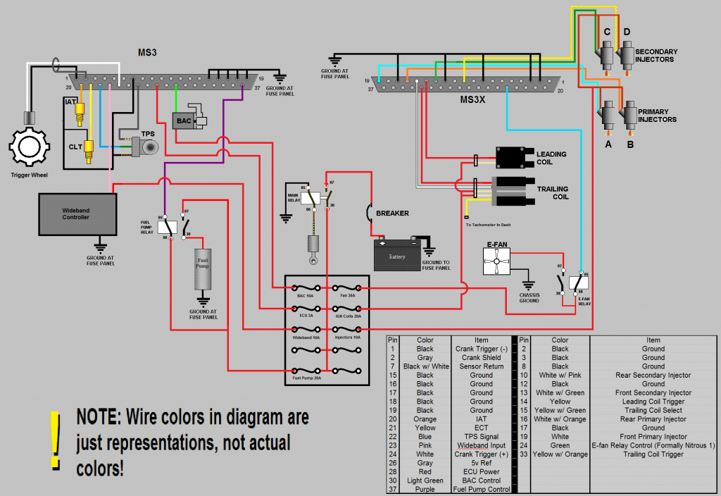
Hardware manual covering specific wiring and configuration of your v mainboard with ms3x as shown above running firmware ms3 x. Rheem tankless water heater wiring diagram; To provide improved engine performance, better fuel economy, and reduced exhaust emissions, megasquirt ii can control spark advance (timing), and this advance is programmable by the user. Ms2 + ms3 stepper motor idle valve options; This is a quick video going over the basic wiring of a megasquirt ecu into my z turbo build.
 Source: aaroncake.net
Power is a heavy red wire, ; Wiring diagram for bt openreach master socket 5c Wiring diagram/schematic for a4988 stepper motor driver with arduino and stepper motor. The normally closed terminals of the fault signalling contacts are connected to the undervoltage release coil of the circuit breaker. From many options on the web we are sure this image could be a best guide for you, and we sincerely hope you are satisfied with what we present.
This site is an open community for users to share their favorite wallpapers on the internet, all images or pictures in this website are for personal wallpaper use only, it is stricly prohibited to use this wallpaper for commercial purposes, if you are the author and find this image is shared without your permission, please kindly raise a DMCA report to Us.
If you find this site value, please support us by sharing this posts to your favorite social media accounts like Facebook, Instagram and so on or you can also save this blog page with the title ms2 wiring diagram by using Ctrl + D for devices a laptop with a Windows operating system or Command + D for laptops with an Apple operating system. If you use a smartphone, you can also use the drawer menu of the browser you are using. Whether it’s a Windows, Mac, iOS or Android operating system, you will still be able to bookmark this website.
Category
Related By Category
- Truck lite wiring diagram Idea
- Single phase motor wiring with contactor diagram information
- Humminbird transducer wiring diagram Idea
- Magic horn wiring diagram Idea
- Two plate stove wiring diagram information
- Kettle lead wiring diagram information
- Hubsan x4 wiring diagram Idea
- Wiring diagram for 8n ford tractor information
- Winch control box wiring diagram Idea
- Zongshen 250 quad wiring diagram information