Mr52 wiring diagram Idea
Home » Trending » Mr52 wiring diagram Idea
Your Mr52 wiring diagram images are ready in this website. Mr52 wiring diagram are a topic that is being searched for and liked by netizens now. You can Find and Download the Mr52 wiring diagram files here. Get all free photos and vectors.
If you’re searching for mr52 wiring diagram pictures information related to the mr52 wiring diagram keyword, you have visit the right blog. Our site always gives you suggestions for seeking the maximum quality video and picture content, please kindly search and find more informative video articles and graphics that match your interests.
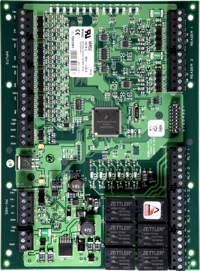
Mr52 Wiring Diagram. The mr52 and mr53 both will function in low power mode when powered by a 802.3af power source. (609 m) maximum total length. About this guide this guide explains how to assemble and install the synergis cloud link appliance and associated hardware components. Despite being in low power mode, the device can still supply full 802.11ac capabilities.
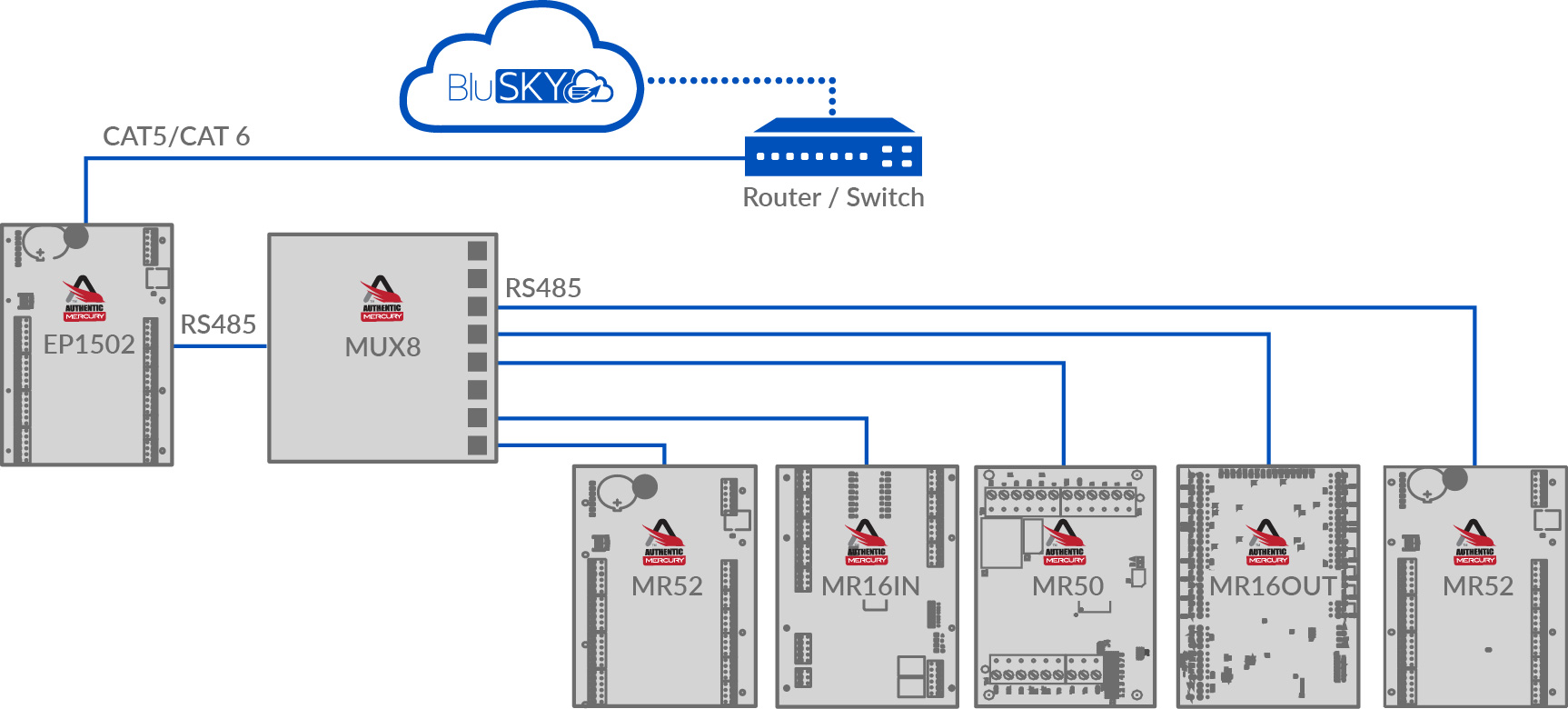
 Mercury MR52 Series 2 & 3 Serial I/O Controllers BluINFO From knowledge.blub0x.com
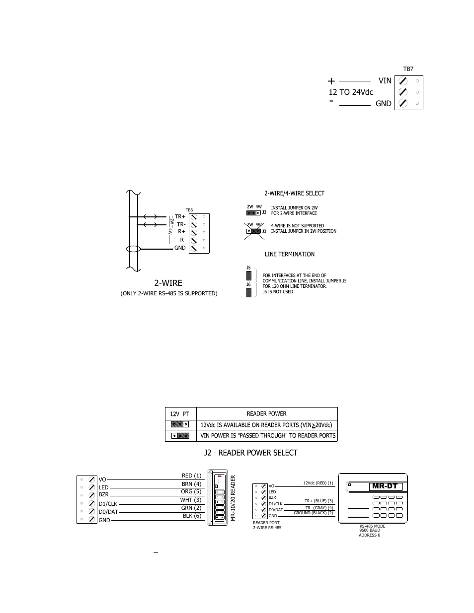
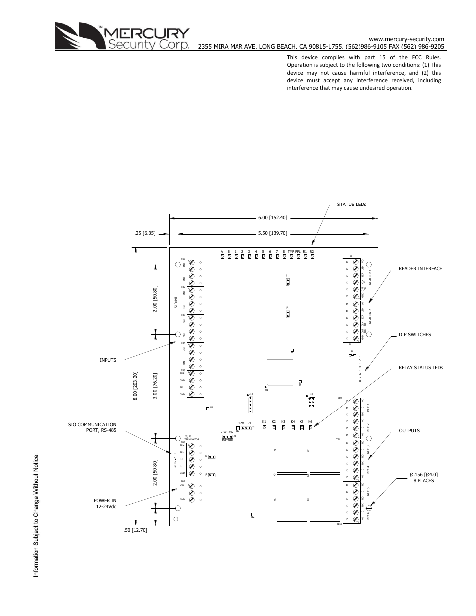
The vout terminal on tb7 is the same as vin. The last expansion module on the bus must have jumper j5 installed for adcacmr52 modules and j4 installed for Up to eight total expansion modules may be wired. Reader contact/ relays reader 2 reader 1 j7 adc ac lp1501 k 12 vdc * reader reader 1 if reader 1 is not wired to an expansion module, it can be wired to a. About this guide this guide explains how to assemble and install the synergis cloud link appliance and associated hardware components. Hardware interface and card format settings are loaded through software commands.
Reader port 1 typical d1/d0 or clock/data reader reader port 2 typical d1/d0 or clock/data reader f/2f reader reader port 1.
The relay contacts are rated at 5 a @ 30 vdc, dry contact configuration. Authentic mercury mr serial input/output (sio) devices represent the secondary level in mercury’s distributed architecture. Hardware interface and card format settings are loaded through software commands. Firmware revision up to 11. Keypads and integrated keypad readers are also supported. Communication wiring (sio communication port):
 Source: knowledge.blub0x.com
Make power connection with minimum of 18 awg wires. Firmware revision up to 11. Lnl series 2 overview lenel offers a dual reader interface (dri) module for access control solutions. For a list of all security center and autovu™ documentation, go to the gtap documents page. While in low power mode, the mr52 and mr53 both will disable its air marshal radio as well as three out of four transmit streams on the 2.4 ghz band.
 Source: wiringdiagram.2bitboer.com
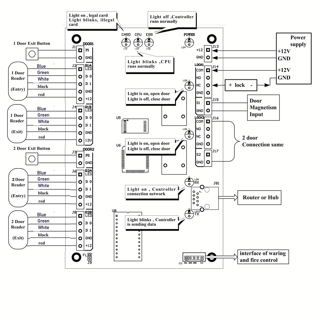
The relay contacts are rated at 5 a @ 30 vdc, dry contact configuration. This selection is made via jumper j2 and is made for both reader ports. Wiring the reader incorrectly may permanently damage the reader. 9600, 19200, 38400 or 115200 bps reader ports two reader ports power: Keypads and integrated keypad readers are also supported.
 Source: support.remotelock.com
The total cable length is limited to 500 feet (152 meters). In this short video tutorial we take a look at how to set up the mercury mr50 and mr52 panels and add them to security center. Request to exit (rex) device may require power. Via ttl signaling from series 1 mr52 reader port. Authentic mercury mr serial input/output (sio) devices represent the secondary level in mercury’s distributed architecture.
 Source: wiring121.blogspot.com
Lnl series 2 overview lenel offers a dual reader interface (dri) module for access control solutions. Communication wiring (sio communication port): When you visit any website, it may store or retrieve. Locate the power source as close to the mr52 as possible. While in low power mode, the mr52 and mr53 both will disable its air marshal radio as well as three out of four transmit streams on the 2.4 ghz band.
 Source: support.remotelock.com
Data 0 and data 1 wires for wiegand may be reused for osdp. The mr52 and mr53 both will function in low power mode when powered by a 802.3af power source. Communication wiring (sio communication port): Reader port 1 typical d1/d0 or clock/data reader reader port 2 typical d1/d0 or clock/data reader f/2f reader reader port 1. The devices provide flexibility ensuring they can choose the controller that best fits their needs.
 Source: carlosvicentederoux.org
The total cable length is limited to 500 feet (152 meters). The relay contacts are rated at 5 a @ 30 vdc, dry contact configuration. 12 vdc, or input voltage passed th rough (pt), 125 ma maximum per reader port. The mr52 is an ideal choice for a versatile and reliable interface panel for. Make power connection with minimum of 18 awg wires.
 Source: manualzz.com
The devices provide flexibility ensuring they can choose the controller that best fits their needs. Most access control card readers, keypads, or readers with keypads that use standard wiegand data1/data0. About this guide this guide explains how to assemble and install the synergis cloud link appliance and associated hardware components. When upgrading to a hid signo reader, ensure proper connections as defined above. The mr52 is an ideal choice for a versatile and reliable interface panel for.
 Source: support.remotelock.com
When upgrading to a hid signo reader, ensure proper connections as defined above. Use twisted pair (minimum 24 awg) with drain wire and shield for communication. The devices provide flexibility ensuring they can choose the controller that best fits their needs. Most access control card readers, keypads, or readers with keypads that use standard wiegand data1/data0. Wiring the reader incorrectly may permanently damage the reader.
 Source: usermanual.wiki
(1,219 m) maximum for communication. Reader contact/ relays reader 2 reader 1 j7 adc ac lp1501 k 12 vdc * reader reader 1 if reader 1 is not wired to an expansion module, it can be wired to a. Hardware interface and card format settings are loaded through software commands. Firmware revision up to 11. Data 0 and data 1 wires for wiegand may be reused for osdp.
 Source: manualsdir.com
Series 1 mr52 reader port: Via ttl signaling from series 1 mr52 reader port. Mercury mr50 series 2 & 3 serial i/o controllers. The devices provide flexibility ensuring they can choose the controller that best fits their needs. The mr52 and mr53 both will function in low power mode when powered by a 802.3af power source.
 Source: knowledge.blub0x.com
Request to exit (rex) device may require power. The mr52 and mr53 both will function in low power mode when powered by a 802.3af power source. The vout terminal on tb7 is the same as vin. Reader contact/ relays reader 2 reader 1 j7 adc ac lp1501 k 12 vdc * reader reader 1 if reader 1 is not wired to an expansion module, it can be wired to a. Use twisted pairs (minimum 24 awg) with drain wire and shield for communication.

Mercury mr50 series 2 & 3 serial i/o controllers. While in low power mode, the mr52 and mr53 both will disable its air marshal radio as well as three out of four transmit streams on the 2.4 ghz band. Despite being in low power mode, the device can still supply full 802.11ac capabilities. Standard door contacts will not require power. The mr52 accepts 12 to 24 vdc for power on tb7.
 Source: knowledge.blub0x.com
Wiring the reader incorrectly may permanently damage the reader. Most access control card readers, keypads, or readers with keypads that use standard wiegand data1/data0. Despite being in low power mode, the device can still supply full 802.11ac capabilities. The mr50 series 2 & 3 sio are economical single card reader interface. Keypads and integrated keypad readers are also supported.
 Source: securitycameraking.com
Use twisted pairs (minimum 24 awg) with drain wire and shield for communication. Use twisted pair (minimum 24 awg) with drain wire and shield for communication. Use twisted pairs (minimum 24 awg) with drain wire and shield for communication. (1,219 m) maximum for communication. Communication wiring (sio communication port):
 Source: manualsdir.com
Hardware interface and card format settings are loaded through software commands. When upgrading to a hid signo reader, ensure proper connections as defined above. While in low power mode, the mr52 and mr53 both will disable its air marshal radio as well as three out of four transmit streams on the 2.4 ghz band. Firmware revision up to 11. (609 m) maximum total length.
 Source: mercury-security.com
(1,219 m) maximum for communication. This selection is made via jumper j2 and is made for both reader ports. When upgrading to a hid signo reader, ensure proper connections as defined above. In this short video tutorial we take a look at how to set up the mercury mr50 and mr52 panels and add them to security center. Up to eight total expansion modules may be wired.
 Source: carlosvicentederoux.org
9600, 19200, 38400 or 115200 bps reader ports two reader ports power: 12 vdc, or input voltage passed th rough (pt), 125 ma maximum per reader port. Reader contact/ relays reader 2 reader 1 j7 adc ac lp1501 k 12 vdc * reader reader 1 if reader 1 is not wired to an expansion module, it can be wired to a. Reader port 1 typical d1/d0 or clock/data reader reader port 2 typical d1/d0 or clock/data reader f/2f reader reader port 1. Hardware interface and card format settings are loaded through software commands.
 Source: support.remotelock.com
While in low power mode, the mr52 and mr53 both will disable its air marshal radio as well as three out of four transmit streams on the 2.4 ghz band. The total cable length is limited to 500 feet (152 meters). The mr50 series 2 & 3 sio are economical single card reader interface. Reader port 1 typical d1/d0 or clock/data reader reader port 2 typical d1/d0 or clock/data reader f/2f reader reader port 1. Hardware interface and card format settings are loaded through software commands.
This site is an open community for users to do submittion their favorite wallpapers on the internet, all images or pictures in this website are for personal wallpaper use only, it is stricly prohibited to use this wallpaper for commercial purposes, if you are the author and find this image is shared without your permission, please kindly raise a DMCA report to Us.
If you find this site adventageous, please support us by sharing this posts to your preference social media accounts like Facebook, Instagram and so on or you can also bookmark this blog page with the title mr52 wiring diagram by using Ctrl + D for devices a laptop with a Windows operating system or Command + D for laptops with an Apple operating system. If you use a smartphone, you can also use the drawer menu of the browser you are using. Whether it’s a Windows, Mac, iOS or Android operating system, you will still be able to bookmark this website.
Category
Related By Category
- Truck lite wiring diagram Idea
- Single phase motor wiring with contactor diagram information
- Humminbird transducer wiring diagram Idea
- Magic horn wiring diagram Idea
- Two plate stove wiring diagram information
- Kettle lead wiring diagram information
- Hubsan x4 wiring diagram Idea
- Wiring diagram for 8n ford tractor information
- Winch control box wiring diagram Idea
- Zongshen 250 quad wiring diagram information