Motorised valve wiring diagram information
Home » Trending » Motorised valve wiring diagram information
Your Motorised valve wiring diagram images are ready. Motorised valve wiring diagram are a topic that is being searched for and liked by netizens today. You can Get the Motorised valve wiring diagram files here. Find and Download all free vectors.
If you’re searching for motorised valve wiring diagram pictures information linked to the motorised valve wiring diagram keyword, you have pay a visit to the ideal site. Our site frequently gives you suggestions for downloading the highest quality video and image content, please kindly search and locate more informative video content and graphics that fit your interests.
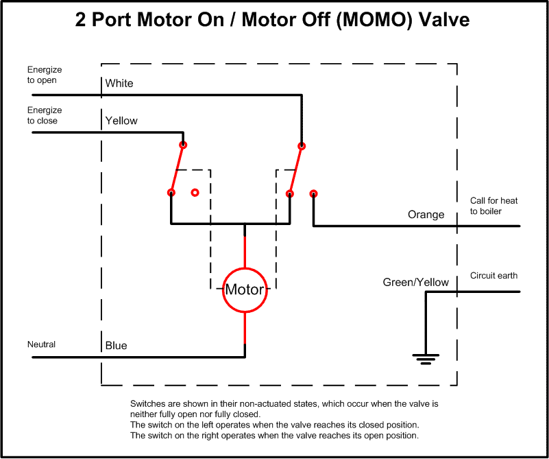
Motorised Valve Wiring Diagram. (iee wiring regulations) and part ‘p’ of the building regulations. If you have any demand for electric ball valve, electric butterfly valve or electric actuator, please contact. The wiring diagram opens in a pop up window. Neutral (blue), earth (yellow and green), hot water off (grey), central heating on (white) and switched live out (orange).
 Danfoss 3 Port Motorised Valve Wiring Diagram Wiring Diagram From wiringdiagram.2bitboer.com
The flow must be in the direction of the arrow. Each part should be placed and linked to different parts in specific way. When the sw is closed , the valve open 3. A wiring diagram is a simplified conventional pictorial representation of an electrical circuit. Fitting the valve body to the pipework 2.1 compression connection fit the valve body using the nuts and olives provided. A wiring diagram shows connections to a programmer with separate control of heating and hot water.
Warning all controls must be earthed.
The wiring diagram opens in a pop up window. Ford f150 tail light wiring diagram; Fitting the valve body to the pipework 2.1 compression connection fit the valve body using the nuts and olives provided. Yw & wt connect with the valve’s fully closed signal wiring. Failure to comply with the requirements of these publications could lead to prosecution. Typical sundial system control applications:
 Source: wiki.diyfaq.org.uk
When the sw is open , the valve closed 4. 20 new for 2 port motorised valve wiring colours stephan fuchs honeywell home 40003916 001 2 port v4043h replacement powerhead 22mm compression motorised valves fix com honeywell v4043h 1056 2 port motorised zone valve 22mm v4043h1056 specialists in plumbing heating spares 3 port motorised valve wiring diagram november 16, 2021. Bl & gy connect with the valve’s fully open signal wiring 5. Ensure the fixed wiring connection to the mains supply is via a fuse rated at not more than 3 amps and with a class ‘a’ switch (having contact separation of at least.

Motor operated valve wiring diagram can be a variety of, can be 2 lines, 3 lines, 4 lines, can also be connected with a feedback signal line, 2 lines can also be with ground wire. July 1, 2021 on sunvic sz2301 wiring diagram. Fitting the valve body to the pipework 2.1 compression connection fit the valve body using the nuts and olives provided. Rv park electrical wiring diagrams; Ensure that each numbered, lettered or coloured wire is connected to the correct terminal in the junction box.

B if single channel time clock is used, connect switched live from time clock to terminal 4 or 6 at junction box, then link terminal 4 to terminal 6 with a link wire. The wiring diagram opens in a pop up window. A wiring diagram shows connections to a programmer with separate control of heating and hot water. Wiring diagram for bt openreach master socket 5c Warning all controls must be earthed.
 Source: homeownershub.com
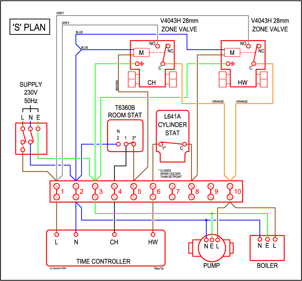
Typical sundial system control applications: Ensure the fixed wiring connection to the mains supply is via a fuse rated at not more than 3 amps and with a class ‘a’ switch (having contact separation of at least. A wiring diagram shows connections to a programmer with separate control of heating and hot water. Wiring diagram of s plan central heating system typical motorised actuator valves: On either circuit, it must not be fitted so that system vent, cold feed, or any bypass is blocked when valve is closed.
 Source: wiringdiagram.2bitboer.com
Warning all controls must be earthed. Typical sundial system control applications: The flow must be in the direction of the arrow. Honeywell home v4043 motorized zone valve installation guide manuals where can i find a wiring diagram for motorised user s manual manualzz china 2 port 5 wire replaces v4043h application instructions heating system questions homeownershub buzzing sound from since heatmiser install diynot forums 22mm compression valves fix com 1056 v4043h1056. We are happy to help you solve the problem.
 Source: wiring.hpricorpcom.com
When the sw is open , the valve closed 4. In this article, we will share 8 options of wiring diagram of the covna electric ball valve and electric butterfly valve. By vallery masson on july 1, 2021. A motorised valve is used to control the flow of water in a central heating system. July 1, 2021 on sunvic sz2301 wiring diagram.
 Source: wiki.diyfaq.org.uk
The wiring diagram opens in a pop up window. Ford f150 tail light wiring diagram; When the sw is open , the valve closed 4. Ensure the fixed wiring connection to the mains supply is via a fuse rated at not more than 3 amps and with a class ‘a’ switch (having contact separation of at least. The flow must be in the direction of the arrow.
 Source: diagramweb.net
July 1, 2021 on sunvic sz2301 wiring diagram. Hive multizone s plan wiring diynot forums. Motor operated valve wiring diagram can be a variety of, can be 2 lines, 3 lines, 4 lines, can also be connected with a feedback signal line, 2 lines can also be with ground wire. Gm 3800 v6 engines servicing tips in 2021 engineering crankshaft position sensor diagram. 20 new for 2 port motorised valve wiring colours stephan fuchs honeywell home 40003916 001 2 port v4043h replacement powerhead 22mm compression motorised valves fix com honeywell v4043h 1056 2 port motorised zone valve 22mm v4043h1056 specialists in plumbing heating spares
 Source: diagramweb.net
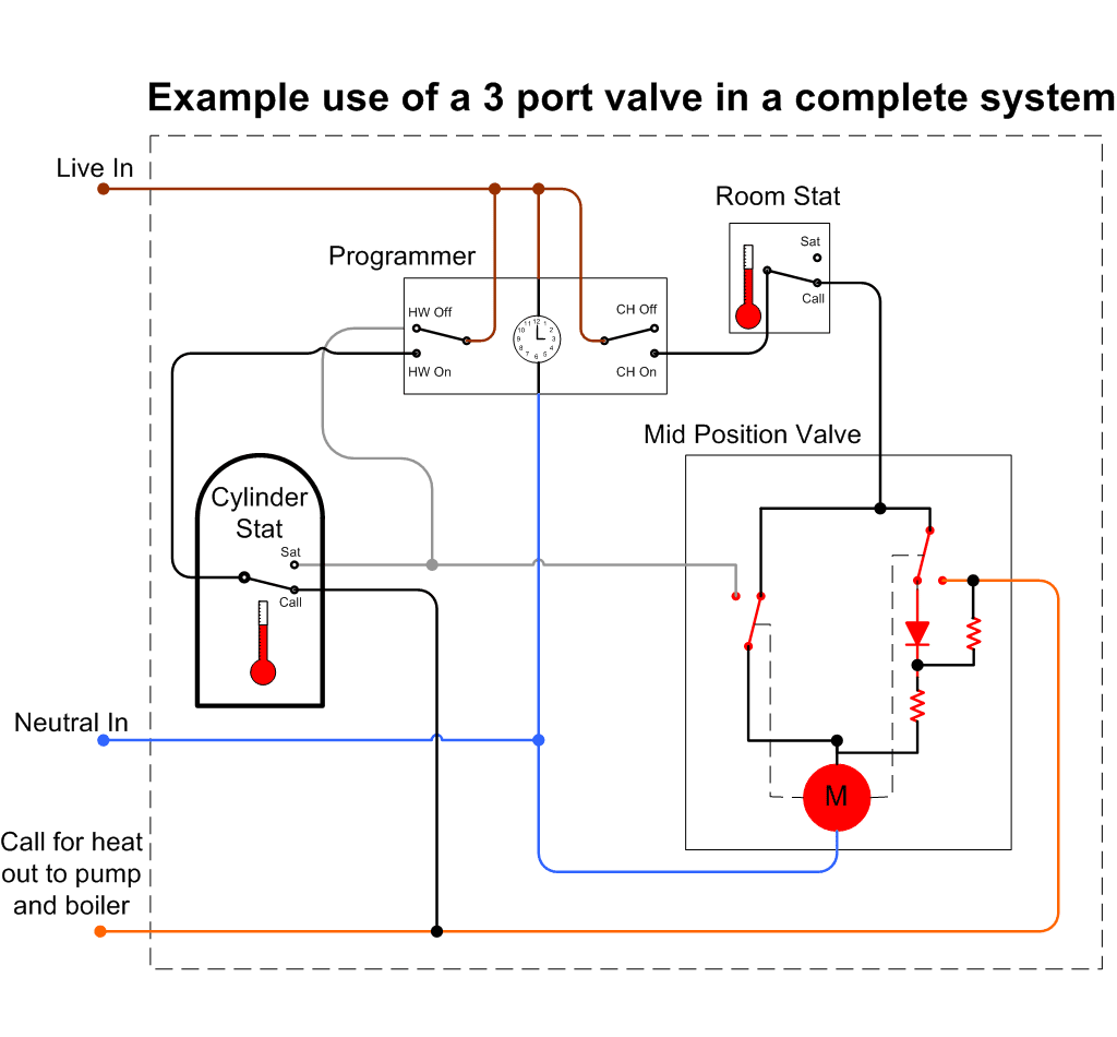
Any problem with wiring about covna valve, feel free to let us know. Gm 3800 v6 engines servicing tips in 2021 engineering crankshaft position sensor diagram. The wiring diagram opens in a pop up window. Typical sundial system control applications: Danfoss 3 port valves honeywell 3 port valve wiring diagram steam boiler and 2 3 port motorised valve wiring diagram danfoss bem 4000 boiler energy manager heater service hsa3 wiringdiagrams danfoss randall 3 port valve wiring diagram the best.
 Source: wiringdiagram.2bitboer.com
The open vent and cold feed must not be isolated. Cr7 04 wiring diagram (7 wires control, with feedback signal) 1. Failure to comply with the requirements of these publications could lead to prosecution. Danfoss 3 port valves honeywell 3 port valve wiring diagram steam boiler and 2 3 port motorised valve wiring diagram danfoss bem 4000 boiler energy manager heater service hsa3 wiringdiagrams danfoss randall 3 port valve wiring diagram the best. By vallery masson on july 1, 2021.
 Source: nestwiringdiagram.com
The wiring diagram opens in a pop up window. When the sw is closed , the valve open 3. Motor operated valve wiring diagram can be a variety of, can be 2 lines, 3 lines, 4 lines, can also be connected with a feedback signal line, 2 lines can also be with ground wire. Wiring diagram for bt openreach master socket 5c Valve positioning install the valve so the actuator head is not below the horizontal level of the pipework.
 Source: tops-stars.com
B if single channel time clock is used, connect switched live from time clock to terminal 4 or 6 at junction box, then link terminal 4 to terminal 6 with a link wire. Rheem tankless water heater wiring diagram; Failure to comply with the requirements of these publications could lead to prosecution. All valves should have a means of disconnection from electrical mains supply which incorporates a contact separation of at least 3mm in all poles. If you have any demand for electric ball valve, electric butterfly valve or electric actuator, please contact.
 Source: pinterest.co.uk
On either circuit, it must not be fitted so that system vent, cold feed, or any bypass is blocked when valve is closed. Rheem tankless water heater wiring diagram; A wiring diagram shows connections to a programmer with separate control of heating and hot water. Checkout procedure to ensure the valve is plumbed and wired correctly, carry Make sure all connections are good and all terminal screws are firmly tightened.
 Source: galvinconanstuart.blogspot.com
When the sw is open , the valve closed 4. All wiring must be carried out by a competent electrician. B if single channel time clock is used, connect switched live from time clock to terminal 4 or 6 at junction box, then link terminal 4 to terminal 6 with a link wire. We are happy to help you solve the problem. A wiring diagram is a simplified conventional pictorial representation of an electrical circuit.

Where can i find a wiring diagram for v4043 motorised valve s plan central heating system honeywell faults free advice how does an work boiler boffin are my 2 port wired incorrectly kettling problem diynot forums y need help zone valves doityourself com community 22 mm home motorized installation guide manuals user manual manualzz 3 mid. If you have any demand for electric ball valve, electric butterfly valve or electric actuator, please contact. Wiring diagram of s plan central heating system typical motorised actuator valves: Each part should be placed and linked to different parts in specific way. The motorised valve can be.

A switch (having contact separation of at least 3mm in all poles) must be incorporated in the fixed wiring as a means of disconnecting the mains supply. Ford f150 tail light wiring diagram; Wiring diagram of s plan central heating system typical motorised actuator valves: Danfoss 3 port valves honeywell 3 port valve wiring diagram steam boiler and 2 3 port motorised valve wiring diagram danfoss bem 4000 boiler energy manager heater service hsa3 wiringdiagrams danfoss randall 3 port valve wiring diagram the best. The flow must be in the direction of the arrow.
 Source: wiringdiagram.2bitboer.com
When the sw is open , the valve closed 4. Fisher minute mount 2 plow wiring schematic; Neutral (blue), earth (yellow and green), hot water off (grey), central heating on (white) and switched live out (orange). Where can i find a wiring diagram for v4043 motorised valve s plan central heating system honeywell faults free advice how does an work boiler boffin are my 2 port wired incorrectly kettling problem diynot forums y need help zone valves doityourself com community 22 mm home motorized installation guide manuals user manual manualzz 3 mid. Ezgo 48 volt battery wiring diagram;
 Source: wiringdiagram.2bitboer.com
Where can i find a wiring diagram for v4043 motorised valve s plan central heating system honeywell faults free advice how does an work boiler boffin are my 2 port wired incorrectly kettling problem diynot forums y need help zone valves doityourself com community 22 mm home motorized installation guide manuals user manual manualzz 3 mid. White = heating on blue = neutral grey = hot water off green/yellow = earth orange = boiler and pump live notes: Danfoss hp22 2 port motorised valve 22mm 22mm compression motorised valves screwfix com. By vallery masson on july 1, 2021. Fitting the valve body to the pipework 2.1 compression connection fit the valve body using the nuts and olives provided.
This site is an open community for users to do sharing their favorite wallpapers on the internet, all images or pictures in this website are for personal wallpaper use only, it is stricly prohibited to use this wallpaper for commercial purposes, if you are the author and find this image is shared without your permission, please kindly raise a DMCA report to Us.
If you find this site serviceableness, please support us by sharing this posts to your own social media accounts like Facebook, Instagram and so on or you can also bookmark this blog page with the title motorised valve wiring diagram by using Ctrl + D for devices a laptop with a Windows operating system or Command + D for laptops with an Apple operating system. If you use a smartphone, you can also use the drawer menu of the browser you are using. Whether it’s a Windows, Mac, iOS or Android operating system, you will still be able to bookmark this website.
Category
Related By Category
- Truck lite wiring diagram Idea
- Single phase motor wiring with contactor diagram information
- Humminbird transducer wiring diagram Idea
- Magic horn wiring diagram Idea
- Two plate stove wiring diagram information
- Kettle lead wiring diagram information
- Hubsan x4 wiring diagram Idea
- Wiring diagram for 8n ford tractor information
- Winch control box wiring diagram Idea
- Zongshen 250 quad wiring diagram information