Motorcycle regulator wiring diagram Idea
Home » Trending » Motorcycle regulator wiring diagram Idea
Your Motorcycle regulator wiring diagram images are available in this site. Motorcycle regulator wiring diagram are a topic that is being searched for and liked by netizens now. You can Find and Download the Motorcycle regulator wiring diagram files here. Get all royalty-free photos.
If you’re looking for motorcycle regulator wiring diagram images information linked to the motorcycle regulator wiring diagram topic, you have visit the right site. Our website always gives you suggestions for downloading the highest quality video and image content, please kindly search and find more enlightening video content and images that fit your interests.
Motorcycle Regulator Wiring Diagram. Motorcycle regulator rectifier wiring diagram. Ruckus gy6 swap wiring diagram. Motorcycle regulator rectifier wiring diagram. The best other is always to use a verified and accurate 6 wire regulator rectifier wiring diagram that’s provided from a trusted source.
 Voltage regulator, A summary Techy at day, Blogger at From mastercircuits.blogspot.mx
For instance , if a module is usually powered up and it sends out a new signal of half the voltage and the technician will not know this, he would think he has a challenge, as he would. 12 car alternator voltage regulator wiring diagram alternator car alternator electrical diagram. Others have., well you get the idea. The 3 phase output from the alternator is sequentially applied across three power transistors which basically act like shunting devices for the alternator current. When something is wired in parallel it means it is wired alongside a circuit with its own positive wire. By facybulka posted on august 5, 2018 114 views.
It’s supposed to assist all of the typical person in creating a correct system.
Some have the wires drawn with the appropriate color. Lowest prices for universal 4 wire 2 phase motorcycle regulator rectifier 12v quad. Motorcycle regulator rectifier buy motorcycle regulator rectifier rectifier mitsubishi alternator motorcycle rectifier regulator product on. Some have each wire with a color id initial like g for green or br for brown and the like. There’ll be principal lines which are represented by l1, l2, l3, and so on. 7 wire motorcycle regulator wiring diagram.
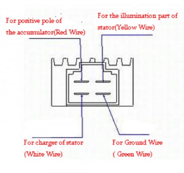 Source: tankbig.com
To do a basic test to establish that your dynamo is working: Full wave regulator schematic, motorcycle regulator, hid charging, regulator diagram, hid conversion, 5 wire regulator, rr schematic,. The coil in the diagram is shown attached at one end to earth, then just a few coils up is the green wire take off, then close to the end of the coil is the yellow with white tracer take off and right at the end of the coil is the yellow wire take off. (see diagram below) regulator rectifiers you must use resisted spark plugs as circuitry is sensitive. Motorcycle regulator rectifier buy motorcycle regulator rectifier rectifier mitsubishi alternator motorcycle rectifier regulator product on.
 Source: facybulka.me
Motorcycle regulator rectifier wiring diagram. 4 wire voltage regulator wiring diagram wiring diagram is a simplified all right pictorial representation of an electrical circuit it shows the components of the circuit as simplified shapes and the capability and signal links together with the devices. For instance , if a module is usually powered up and it sends out a new signal of half the voltage and the technician will not know this, he would think he has a challenge, as he would. 12 car alternator voltage regulator wiring diagram alternator car alternator electrical diagram. How to rewire a lucas dynamo and regulator unit matchless.
 Source: mastercircuits.blogspot.mx
Motorcycle regulator rectifier wiring diagram wiring diagram line wiring diagram wiring diagram line we are make source the schematics, wiring diagrams and technical photos Universal voltage regulator rectifier electrical for motorcycle and boat motors diy engines online in vietnam b07l94ntsb tester circuit homemade projects compre flwd 4 wire full wave black 12v dc bike quad barato frete grátis avaliações reais com fotos. Voltage regulator voltage regulator rectifier fit for gy6 125cc 150cc 6. Motorcycle regulator rectifier wiring diagram wiring diagram line wiring diagram wiring diagram line we are make source the schematics, wiring diagrams and technical photos Before you search for a.
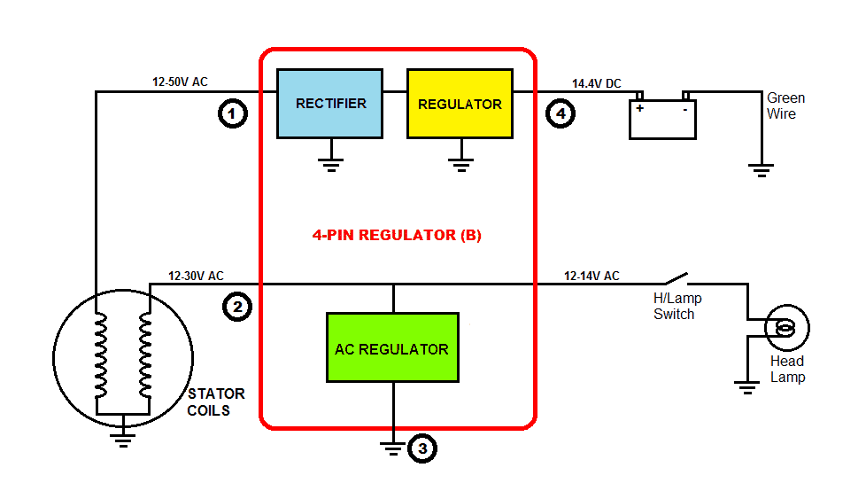 Source: wiringdiagram.2bitboer.com
Gy6 wiring diagram 150cc go kart 150cc scooter motorcycle wiring. Motorcycle regulator rectifier wiring diagram from i.pinimg.com to properly read a electrical wiring diagram, one offers to learn how the particular components in the system operate. Each component should be set and linked to other parts in specific way. Wiring diagram 5 pin rectifier wiring diagram jeff sessions. Voltage regulator voltage regulator rectifier fit for gy6 125cc 150cc 6.
 Source: reviewmotors.co
Universal voltage regulator rectifier electrical for motorcycle and boat motors diy engines online in vietnam b07l94ntsb tester circuit homemade projects compre flwd 4 wire full wave black 12v dc bike quad barato frete grátis avaliações reais com fotos. 3 phase motorcycle voltage regulator circuits homemade circuit projects understanding wiring universal rectifier electrical for and boat motors diy engines online in taiwan b07l94ntsb tester building a electronics forums honda cg125 150 zj125 at affordable s free shipping real reviews with photos joom how to test your charging system comprehensive guide. Print the cabling diagram off and use highlighters in order to trace the signal. 7 wire motorcycle regulator wiring diagram. 6 wires motorcycle regulator rectifier plug voltage regulator.
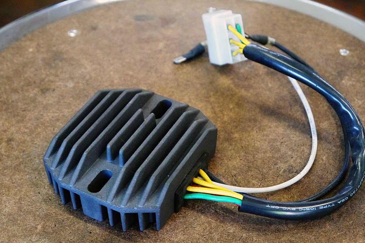 Source: bikeexif.com
Motorcycle regulator rectifier wiring diagram. The 10 100 rectifier plugs into the harness at the same location as the oe rectifier. How to rewire a lucas dynamo and regulator unit matchless. Universal voltage regulator rectifier electrical for motorcycle and boat motors diy engines online in vietnam b07l94ntsb tester circuit homemade projects compre flwd 4 wire full wave black 12v dc bike quad barato frete grátis avaliações reais com fotos. Motorcycle regulator rectifier wiring diagram.
 Source: diagramweb.net
Full wave regulator schematic, motorcycle regulator, hid charging, regulator diagram, hid conversion, 5 wire regulator, rr schematic,. One trick that i use is to print out exactly the same wiring diagram off twice. While these wiring diagrams may seem confusing there is a method to their madness. These simple visual representations all. Before you search for a.
 Source: ebay.co.uk
Wiring diagram 5 pin rectifier wiring diagram jeff sessions. The coil in the diagram is shown attached at one end to earth, then just a few coils up is the green wire take off, then close to the end of the coil is the yellow with white tracer take off and right at the end of the coil is the yellow wire take off. While these wiring diagrams may seem confusing there is a method to their madness. In fact, there can be several methods to the madness, so to speak. Install brown ignition wire the brown ignition wire 3 in diagram at right provides onoff voltage for the regulator.
 Source: kelvin-okl.blogspot.com
Wiring diagram includes several in depth illustrations that show the connection of varied things. M 3 2 2 2 phase 5 wire. One trick that i use is to print out exactly the same wiring diagram off twice. 7 wire motorcycle regulator wiring diagram. To do a basic test to establish that your dynamo is working:

Draw a diagram to map out your wires and connections. It shows the parts of the circuit as streamlined forms as well as the power as well as signal connections between the tools. Wiring diagram includes several in depth illustrations that show the connection of varied things. Otherwise, the structure won’t work as it should be. Some have the wires drawn with the appropriate color.
 Source: schematicandwiringdiagram.blogspot.com
A wiring diagram is a schematic type that uses abstract illustrated symbols to show all of the components of a system. Part of lamberts bikes online library of pdf motorcycle manuals wiring diagrams and technical guides. When something is wired in parallel it means it is wired alongside a circuit with its own positive wire. While these wiring diagrams may seem confusing there is a method to their madness. Disconnect the d & f (or f2) wires from it.
 Source: mastercircuits.blogspot.com
By facybulka posted on august 5, 2018 114 views. Motorcycle regulator wiring diagram motorcycle full wave. Motorcycle regulator rectifier wiring diagram. There’ll be principal lines which are represented by l1, l2, l3, and so on. Draw a diagram to map out your wires and connections.
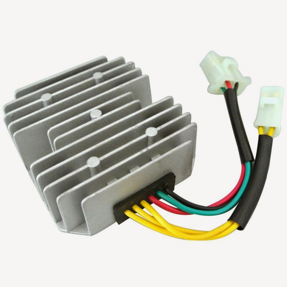 Source: homemade-circuits.com
However, it doesn’t mean link between the cables. Jun 15, my regulator has three wires (1 red, 1 yellow, and 1 black with a ring connector). The best other is always to use a verified and accurate 6 wire regulator rectifier wiring diagram that’s provided from a trusted source. In fact, there can be several methods to the madness, so to speak. Universal voltage regulator rectifier electrical for motorcycle and boat motors diy engines online in vietnam b07l94ntsb tester circuit homemade projects compre flwd 4 wire full wave black 12v dc bike quad barato frete grátis avaliações reais com fotos.
 Source: skippingtheinbetween.blogspot.com
These simple visual representations all. Disconnect the d & f (or f2) wires from it. Motorcycle regulator rectifier wiring diagram. 12 car alternator voltage regulator wiring diagram alternator car alternator electrical diagram. There’ll be principal lines which are represented by l1, l2, l3, and so on.
 Source: schematron.org
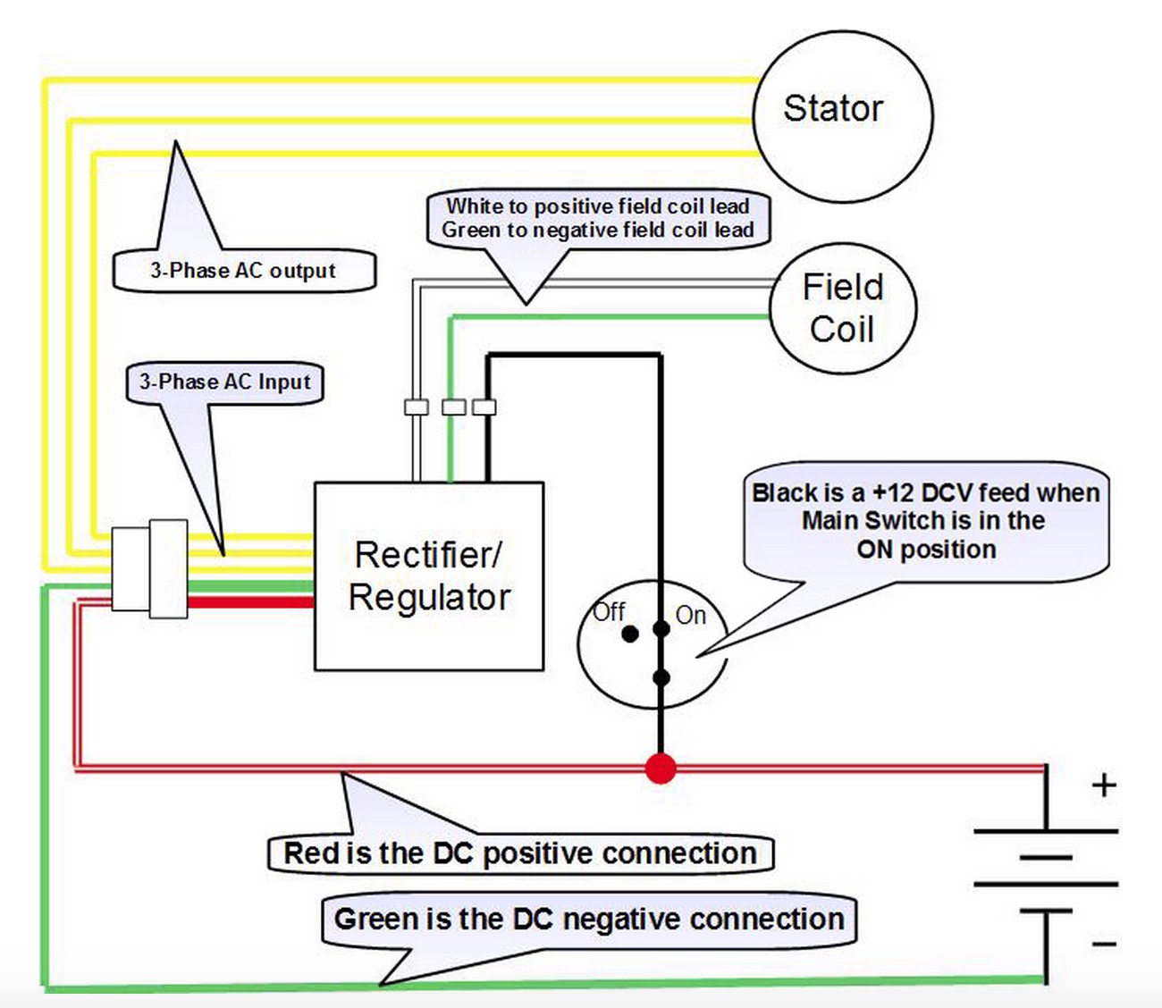
These instructions will be easy to grasp and implement. This type may be found on some motorcycles. The best other is always to use a verified and accurate 6 wire regulator rectifier wiring diagram that’s provided from a trusted source. The red wire from the rr connects to the red wire in the wiring harness. When you employ your finger or even the actual circuit together with your eyes, it may be easy to mistrace the circuit.
Source: etsytivity.blogspot.com
There’ll be principal lines which are represented by l1, l2, l3, and so on. Disconnect the d & f (or f2) wires from it. Some have the wires drawn with the appropriate color. Otherwise, the structure won’t work as it should be. For instance , if a module is usually powered up and it sends out a new signal of half the voltage and the technician will not know this, he would think he has a challenge, as he would.
 Source: reviewmotors.co
Each component should be set and linked to other parts in specific way. These instructions will be easy to grasp and implement. Ruckus gy6 swap wiring diagram. Motorcycle regulator rectifier buy motorcycle regulator rectifier rectifier mitsubishi alternator motorcycle rectifier regulator product on. Some have the wires drawn with the appropriate color.
Source: faceitsalon.com
For instance , if a module is usually powered up and it sends out a new signal of half the voltage and the technician will not know this, he would think he has a challenge, as he would. Dce 6 wire voltage regulator wiring diagram wiring resources. How to rewire a lucas dynamo and regulator unit matchless. (see diagram below) regulator rectifiers you must use resisted spark plugs as circuitry is sensitive. 15 motorcycle regulator rectifier wiring diagram motorcycle wiring voltage regulator electrical wiring.
This site is an open community for users to submit their favorite wallpapers on the internet, all images or pictures in this website are for personal wallpaper use only, it is stricly prohibited to use this wallpaper for commercial purposes, if you are the author and find this image is shared without your permission, please kindly raise a DMCA report to Us.
If you find this site convienient, please support us by sharing this posts to your favorite social media accounts like Facebook, Instagram and so on or you can also save this blog page with the title motorcycle regulator wiring diagram by using Ctrl + D for devices a laptop with a Windows operating system or Command + D for laptops with an Apple operating system. If you use a smartphone, you can also use the drawer menu of the browser you are using. Whether it’s a Windows, Mac, iOS or Android operating system, you will still be able to bookmark this website.
Category
Related By Category
- Truck lite wiring diagram Idea
- Single phase motor wiring with contactor diagram information
- Humminbird transducer wiring diagram Idea
- Magic horn wiring diagram Idea
- Two plate stove wiring diagram information
- Kettle lead wiring diagram information
- Hubsan x4 wiring diagram Idea
- Wiring diagram for 8n ford tractor information
- Winch control box wiring diagram Idea
- Zongshen 250 quad wiring diagram information