Motor encoder wiring diagram information
Home » Trending » Motor encoder wiring diagram information
Your Motor encoder wiring diagram images are ready. Motor encoder wiring diagram are a topic that is being searched for and liked by netizens now. You can Find and Download the Motor encoder wiring diagram files here. Find and Download all free photos and vectors.
If you’re looking for motor encoder wiring diagram images information connected with to the motor encoder wiring diagram keyword, you have pay a visit to the right blog. Our site frequently provides you with hints for seeing the highest quality video and image content, please kindly search and locate more informative video articles and images that fit your interests.
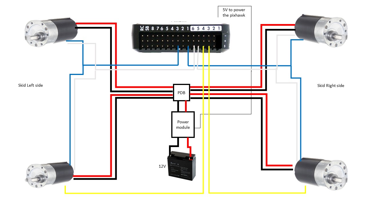
Motor Encoder Wiring Diagram. Wiring up the encoders is pretty simple. There are a wide variety of motor encoder configurations available such as incremental or absolute, optical or magnetic, shafted or hub/hollow shaft, among others. Operating instructions ac motors 21258996 operating instructions moviaxis multi axis servo inverter sew eurodrive brake wiring sew drive calculation diagram toyota celica alternator wiring diagram full version sew. The dc motor with encoder has 6 wires :
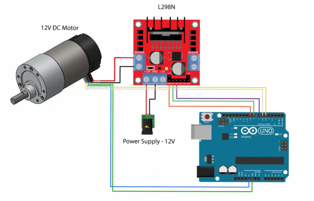 Solved Given The Schematic Of A DC Motor With Encoder Con From chegg.com
Brushless dc motor block diagram. Wiring for a single motor and encoder. Operating instructions ac motors 21258996 operating instructions moviaxis multi axis servo inverter sew eurodrive brake wiring sew drive calculation diagram toyota celica alternator wiring diagram full version sew. To measure a clockwise rotation of a shaft as a positive/forward direction the “top”. If you are only connecting to leds, the simplest connection is just to change the resistors in your original diagram to 2k2, connect them to 12v rather than ground and reverse the led polarity. Motor cable encoder cables cable p/n:
Green red yellow white black lead wire color manufacturer:
• connect the m12 connector as shown in the wiring diagram. Motor configured for high voltage. If you are only connecting to leds, the simplest connection is just to change the resistors in your original diagram to 2k2, connect them to 12v rather than ground and reverse the led polarity. 2007 club car precedent wiring diagram; Wiring for a single motor and encoder. Connection wiring diagram • 8 lead wire type black red white brown blue yellow orange green a b a b • 6 lead wire type [( ):
 Source: tutorial.cytron.io
Note that the encoder pin outa needs to be connected to a hardware interrupt pin (digital pin 2 or 3 on an arduino duemilanove or uno). An encoder works by observing changes to the magnetic field created by a magnet attached to the motor shaft, as the motor rotates the encoder outputs will trigger periodically. 2 wires to power the motor (often labeled as : Encoder wiring schemes can be unique to each encoder and one should follow the diagram or pinout designated on the encoder datasheet. Connection wiring diagram • 8 lead wire type black red white brown blue yellow orange green a b a b • 6 lead wire type [( ):
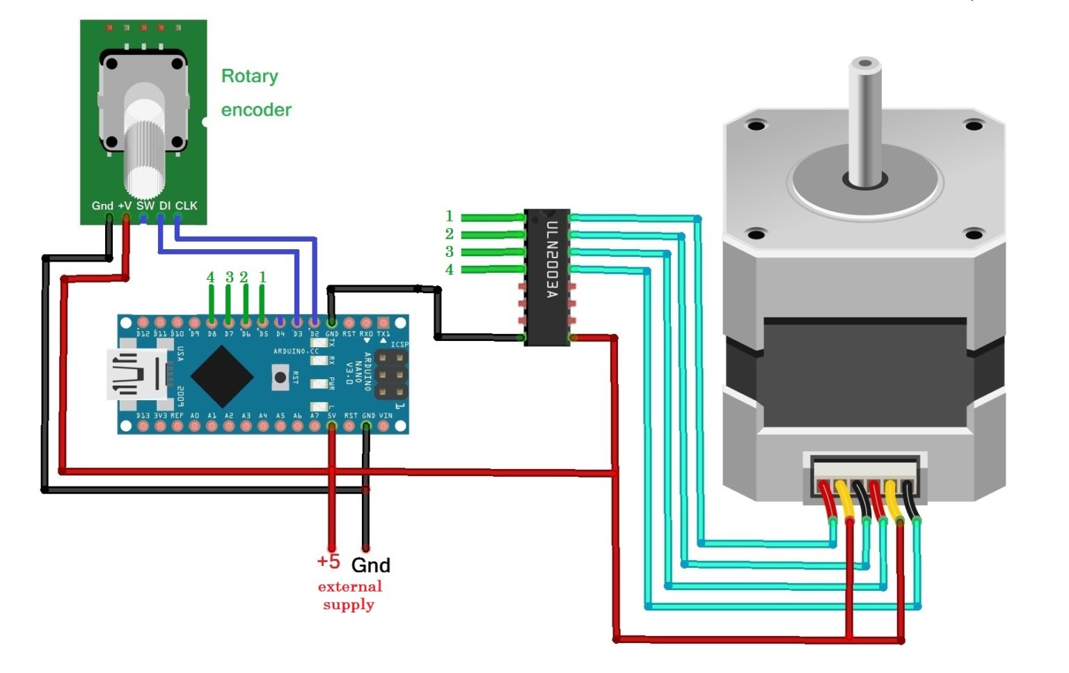 Source: engineersgarage.com
41 brushless dc motor controller wiring diagram. 2007 club car precedent wiring diagram; The cables/connector however seem to carry all (or most) combinations but only the ones that are used goes through to the drive. 230v / 460v motor configured for 460v ( ) supply voltage • brake voltage is 230v (normal reaction time)* * bge/bg rapid reaction time Dec 01, · sew motor wiring in addition encoder wiring diagram along with subaru 2 5 engine diagram along with honda odyssey fuse box moreover weg 12 lead motor wiring diagram fresh sew eurodrive motor wiring diagram furthermore furnace motor wiring diagram as well as 6e2v60 furthermore us together with partes de la maquina de coser along with.
 Source: arduinoecia.com.br
Dec 01, · sew motor wiring in addition encoder wiring diagram along with subaru 2 5 engine diagram along with honda odyssey fuse box moreover weg 12 lead motor wiring diagram fresh sew eurodrive motor wiring diagram furthermore furnace motor wiring diagram as well as 6e2v60 furthermore us together with partes de la maquina de coser along with. Encoder wiring schemes can be unique to each encoder and one should follow the diagram or pinout designated on the encoder datasheet. There’s no need to scrape the mud off the undercarriage. A wiring diagram is a kind of schematic which makes use of abstract photographic symbols to reveal all the interconnections of components in a system. • connect the m12 connector as shown in the wiring diagram.
 Source: chegg.com
Note that the encoder pin outa needs to be connected to a hardware interrupt pin (digital pin 2 or 3 on an arduino duemilanove or uno). Brushless dc motor block diagram. There’s no need to scrape the mud off the undercarriage. To measure a clockwise rotation of a shaft as a positive/forward direction the “top”. Led d4 (green) indicates that the encoder index pulse has been detected, and the quadrature encoder count is being used to generate the commutation signals.
 Source: circuit-diagramz.com
The cables/connector however seem to carry all (or most) combinations but only the ones that are used goes through to the drive. Mcculloch 3516 fuel line diagram The encoder motor (arrow) is mounted on the front of the transfer case and is used to lock it into 4wd. The encoder cable length between the linear encoder and the servo amplifier is maximum 30 m. A wiring diagram is a kind of schematic which makes use of abstract photographic symbols to reveal all the interconnections of components in a system.
 Source: instructables.com
Wiring for a single motor and encoder. Mcculloch 3516 fuel line diagram There’s no need to scrape the mud off the undercarriage. We collect plenty of pictures about brushless dc motor diagram. 41 brushless dc motor controller wiring diagram.
Source: artcolection1.blogspot.com
Motor cable encoder cables cable p/n: This wiring diagram shows basic wiring only, and additional wiring configurations are possible for some i/o. Connection wiring diagram • 8 lead wire type black red white brown blue yellow orange green a b a b • 6 lead wire type [( ): There’s no need to scrape the mud off the undercarriage. The encoder cable length between the linear encoder and the servo amplifier is maximum 30 m.
 Source: diagramweb.net
Green red yellow white black lead wire color manufacturer: Operating instructions ac motors 21258996 operating instructions moviaxis multi axis servo inverter sew eurodrive brake wiring sew drive calculation diagram toyota celica alternator wiring diagram full version sew. Dec 01, · sew motor wiring in addition encoder wiring diagram along with subaru 2 5 engine diagram along with honda odyssey fuse box moreover weg 12 lead motor wiring diagram fresh sew eurodrive motor wiring diagram furthermore furnace motor wiring diagram as well as 6e2v60 furthermore us together with partes de la maquina de coser along with. Note that the encoder pin outa needs to be connected to a hardware interrupt pin (digital pin 2 or 3 on an arduino duemilanove or uno). Mcculloch 3516 fuel line diagram
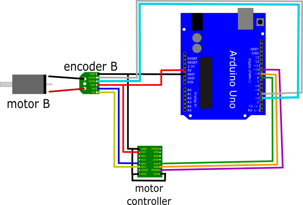 Source: andrewjkramer.net
1996 chevrolet k1500 5.7l wiring diagram; The cables/connector however seem to carry all (or most) combinations but only the ones that are used goes through to the drive. We collect plenty of pictures about brushless dc motor diagram. Led d4 (green) indicates that the encoder index pulse has been detected, and the quadrature encoder count is being used to generate the commutation signals. The female connector has 17 pins male servo motor encoder pin connector
 Source: simple-circuit.com
We collect plenty of pictures about brushless dc motor diagram. An encoder works by observing changes to the magnetic field created by a magnet attached to the motor shaft, as the motor rotates the encoder outputs will trigger periodically. As the wiring diagram shows you’ll need a servo motor. 2007 club car precedent wiring diagram; Pin number] wiring diagram b a red (3) white (2) blue (1) (4) black (5) yellow (6) green b a pin assignments of pk244pa , pk246pa (6)·····(1) pk244pa and pk246pa are connector type motor.
 Source: artcolection1.blogspot.com
M1, m2 , motor power.) 2 wires to power the encoder (often labeled gnd and 3.3v) 2 wires to send signal of position to the microcontroller (arduino) (labeled as encoder output or c1 & c2) 2 wires to power the motor (often labeled as : The cables/connector however seem to carry all (or most) combinations but only the ones that are used goes through to the drive. There are a wide variety of motor encoder configurations available such as incremental or absolute, optical or magnetic, shafted or hub/hollow shaft, among others. A motor encoder is a rotary encoder mounted to an electric motor that provides closed loop feedback signals by tracking the speed and/or position of a motor shaft.
 Source: diagramweb.net
230v / 460v motor configured for 460v ( ) supply voltage • brake voltage is 230v (normal reaction time)* * bge/bg rapid reaction time Green red yellow white black lead wire color manufacturer: 1987 chevy s10 2.8 tbi wiring diagram; We collect plenty of pictures about brushless dc motor diagram. Connect the red wire of the servo motor to the external 5v supply, the black/brown wire to ground and the orange/yellow wire to.
 Source: simple-circuit.com
Motor configured for high voltage. There’s no need to scrape the mud off the undercarriage. (1) cable composition prepare a cable based on the following configuration diagram. Pin number] wiring diagram b a red (3) white (2) blue (1) (4) black (5) yellow (6) green b a pin assignments of pk244pa , pk246pa (6)·····(1) pk244pa and pk246pa are connector type motor. Note that the encoder pin outa needs to be connected to a hardware interrupt pin (digital pin 2 or 3 on an arduino duemilanove or uno).
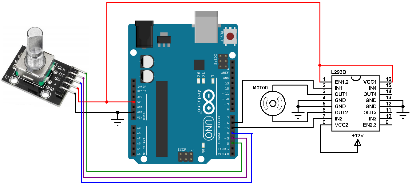 Source: simple-circuit.com
(1) cable composition prepare a cable based on the following configuration diagram. Brushless dc motor block diagram. 41 brushless dc motor controller wiring diagram. When the magnet spins clockwise, output “a” will trigger first, and when rotated counterclockwise on the other hand output “b” will trigger. Connect the red wire of the servo motor to the external 5v supply, the black/brown wire to ground and the orange/yellow wire to.
 Source: wiringall.com
2 wires to power the motor (often labeled as : M1, m2 , motor power.) 2 wires to power the encoder (often labeled gnd and 3.3v) 2 wires to send signal of position to the microcontroller (arduino) (labeled as encoder output or c1 & c2) Mcculloch 3516 fuel line diagram Operating instructions ac motors 21258996 operating instructions moviaxis multi axis servo inverter sew eurodrive brake wiring sew drive calculation diagram toyota celica alternator wiring diagram full version sew. Led d4 (green) indicates that the encoder index pulse has been detected, and the quadrature encoder count is being used to generate the commutation signals.
 Source: osoyoo.com
Motor cable encoder cables cable p/n: 41 brushless dc motor controller wiring diagram. 2007 club car precedent wiring diagram; (1) cable composition prepare a cable based on the following configuration diagram. 230v / 460v motor configured for 460v ( ) supply voltage • brake voltage is 230v (normal reaction time)* * bge/bg rapid reaction time
 Source: artcolection1.blogspot.com
Encoder wiring schemes can be unique to each encoder and one should follow the diagram or pinout designated on the encoder datasheet. The working principle of this servo motor is similar to the normal induction motor. M1, m2 , motor power.) 2 wires to power the encoder (often labeled gnd and 3.3v) 2 wires to send signal of position to the microcontroller (arduino) (labeled as encoder output or c1 & c2) Connection wiring diagram • 8 lead wire type black red white brown blue yellow orange green a b a b • 6 lead wire type [( ): Encoder wiring schemes can be unique to each encoder and one should follow the diagram or pinout designated on the encoder datasheet.
 Source: discuss.ardupilot.org
Stihl fs 85 carburetor diagram; This protocol is proprietary to fanuc and available on all of their control systems. Refer to the “installation and wiring” chapter of the user manual for more detailed wiring information. The encoder motor (arrow) is mounted on the front of the transfer case and is used to lock it into 4wd. The diagram below shows the dimensions (in mm) of the 37d mm line of this header works with standard ″ male headers and our male jumper and precrimped wires.
This site is an open community for users to do submittion their favorite wallpapers on the internet, all images or pictures in this website are for personal wallpaper use only, it is stricly prohibited to use this wallpaper for commercial purposes, if you are the author and find this image is shared without your permission, please kindly raise a DMCA report to Us.
If you find this site helpful, please support us by sharing this posts to your favorite social media accounts like Facebook, Instagram and so on or you can also save this blog page with the title motor encoder wiring diagram by using Ctrl + D for devices a laptop with a Windows operating system or Command + D for laptops with an Apple operating system. If you use a smartphone, you can also use the drawer menu of the browser you are using. Whether it’s a Windows, Mac, iOS or Android operating system, you will still be able to bookmark this website.
Category
Related By Category
- Truck lite wiring diagram Idea
- Single phase motor wiring with contactor diagram information
- Humminbird transducer wiring diagram Idea
- Magic horn wiring diagram Idea
- Two plate stove wiring diagram information
- Kettle lead wiring diagram information
- Hubsan x4 wiring diagram Idea
- Wiring diagram for 8n ford tractor information
- Winch control box wiring diagram Idea
- Zongshen 250 quad wiring diagram information