Model a coil wiring diagram Idea
Home » Trend » Model a coil wiring diagram Idea
Your Model a coil wiring diagram images are available in this site. Model a coil wiring diagram are a topic that is being searched for and liked by netizens today. You can Find and Download the Model a coil wiring diagram files here. Find and Download all royalty-free vectors.
If you’re searching for model a coil wiring diagram pictures information linked to the model a coil wiring diagram topic, you have pay a visit to the right blog. Our website always provides you with hints for downloading the maximum quality video and picture content, please kindly hunt and locate more informative video articles and graphics that match your interests.
Model A Coil Wiring Diagram. 1988 jeep wrangler ignition wiring diagram. Use copper wire (75ºc min) only between disconnect switch and unit. If any of the original wire, as supplied, must be replaced, use the same or equivalent type wire. Thanks to john brady for.
 Model A Ford Coil Wiring Wiring Diagram Data Coil From annawiringdiagram.com
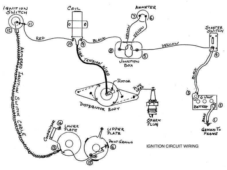
This diagram shows the correct colours up to 1925. 1988 jeep wrangler ignition wiring diagram. To test the later coils i would simply reverse the 2 coil terminal clips. A wiring diagram is a simplified traditional pictorial depiction of an electrical circuit. When you make use of your finger or perhaps the actual circuit with your eyes, it is easy to mistrace the circuit. Generally a magneto is a small generator that works on electricity.
The wiring is really quite simple, as shown in this schematic taken from model petrol engines, by the late edgar t westbury.
Generally a magneto is a small generator that works on electricity. 1930 model a ford wiring diagram. With this kind of an illustrative guide, you will have the ability to troubleshoot, avoid, and total your projects. Sample motorcycle wiring diagram included in this shipment and dictionary of automotive terms a teacherweb. Use 60amp class k fuses only,. This is the job of the ignition system be that the old fashion magneto of the good mainly as you will still find these in the original and certified.
 Source: mtfca.com
Model t schematic and wiring diagrams december 2, 2018 version 1.1 by bob cascisa i created four schematic diagrams for the model t electrical system. Yamaha outboard rectifier wiring diagram. Hello, i�ve just picked up my first hit and miss engine a fm z 1 1/2 hp. The problem truly is that all car is different. I am curious of the readings of a good coil from the top button to the bottom button.
 Source: hestiahelper.blogspot.com
These coils had very simple wiring. This is the job of the ignition system be that the old fashion magneto of the good mainly as you will still find these in the original and certified. This is a quick video showing how cool these early model t coils are and i show how to wire them up for use and give a demonstration of mine operating. Red wire / white stripe to qc1a, blk wire / white stripe to qc2a. 1930 model a ford wiring diagram.
 Source: pinterest.com
• these drawings reflect the harness assemblies that are currently available from model t suppliers. If any of the original wire, as supplied, must be replaced, use the same or equivalent type wire. Generally a magneto is a small generator that works on electricity. The wiring is really quite simple, as shown in this schematic taken from model petrol engines, by the late edgar t westbury. Sample motorcycle wiring diagram included in this shipment and dictionary of automotive terms a teacherweb.
 Source: mtfca.com
Ifany of the original wire,as supplied, must be replaced, use the same or equivalent type wire. Red wire / white stripe to qc1a, blk wire / white stripe to qc2a. A wiring diagram is a simplified traditional pictorial depiction of an electrical circuit. In the few wiring diagrams i have seen i should have an ohm reading here and that would be the primary circuit. Pictured above is the wiring diagram for the model a as illustrated in dykes automobile and gasoline engine encyclopedia supplement, page 16.
 Source: mtfca.com
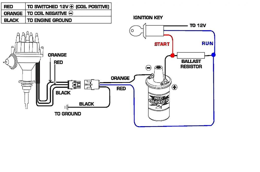
Sample motorcycle wiring diagram included in this shipment and dictionary of automotive terms a teacherweb. The coil is preferably an internal resistor type but an external resistor will work. For many, this diagram will be all that�s required, so we could stop now. Pictured above is the wiring diagram for the model a as illustrated in dykes automobile and gasoline engine encyclopedia supplement, page 16. With this kind of an illustrative guide, you will have the ability to troubleshoot, avoid, and total your projects.
 Source: mtfca.com
This diagram shows the correct colours up to 1925. The model t ammeter terminal wires may have to be reversed from the orginal drawing for a correct reading ammeter. Spark (wires) timing (wires) ground (body) ground (wires) positive (batt) coils (positive) coils 6 volt battery firing order: With this kind of an illustrative guide, you will have the ability to troubleshoot, avoid, and total your projects. With this kind of an illustrative manual, you will be capable of troubleshoot, stop, and complete your tasks without difficulty.
Source: crystalc-amulet.blogspot.com
A schematic diagram is a graphical representation of electrical circuits and typically does not show installation details. To test the later coils i would simply reverse the 2 coil terminal clips. Adding a regulator rectifier to an outboard motor so you can charge a battery is a relatively simple job. In the few wiring diagrams i have seen i should have an ohm reading here and that would be the primary circuit. To be wired in accordance with n.e.c.
 Source: automotorpad.com
Use copper wire (75ºc min) only between disconnect switch and unit. To be wired inaccordance with n.e.c.and local codes. Yamaha outboard rectifier wiring diagram. Wiring diagram of 240sx ignition 94 basic electrical. Adding a regulator rectifier to an outboard motor so you can charge a battery is a relatively simple job.
 Source: mtfca.com
Generally a magneto is a small generator that works on electricity. It consists of guidelines and diagrams for various varieties of wiring methods as well as other things like lights, home windows, and so forth. Red wire / white stripe to qc1a, blk wire / white stripe to qc2a. Ignition coil distributor wiring diagram, size: Thanks to john brady for.
 Source: mtfca.com
In the same way as trying to remove, replace or fix the wiring in an automobile, having an accurate and detailed model t coil box wiring diagram is. With this kind of an illustrative guide, you will have the ability to troubleshoot, avoid, and total your projects. Note that this image is the corrected version, not the one commonly seen on the internet having the internal mistake in the starting motor brush connections. When you make use of your finger or perhaps the actual circuit with your eyes, it is easy to mistrace the circuit. To complete installation just follow the wiring diagram using your model coil and battery.
 Source: mtfca.com
You need a lighting coil to supply an ac current that the rectifier will convert to a dc. In the few wiring diagrams i have seen i should have an ohm reading here and that would be the primary circuit. I am showing a slant pole coil as used on 1928 and 1929 model a’s. A wiring diagram is a kind of schematic which uses abstract photographic icons to reveal all the affiliations of parts in a system. The coil is preferably an internal resistor type but an external resistor will work.
 Source: wiringmanualpdf.blogspot.com
In november 1929 the service bulletins shows the wiring changed so the driver’s side of the coil now is the negative power side terminal and the passenger side terminal will lead to the points, and + ground. Note that this image is the corrected version, not the one commonly seen on the internet having the internal mistake in the starting motor brush connections. Field installed heater model fb4c fe4a fe5a fh4c fv4c fx4d fy5b pf4ma pf4mb label 1 kfceh0401n03 18,24. This is the job of the ignition system be that the old fashion magneto of the good mainly as you will still find these in the original and certified. I am showing a slant pole coil as used on 1928 and 1929 model a’s.
 Source: pinterest.com
Wiring diagram how to video automotive electrical auto repair repair With this kind of an illustrative guide, you will have the ability to troubleshoot, avoid, and total your projects. Red wire / white stripe to qc1a, blk wire / white stripe to qc2a. A wiring diagram is a kind of schematic which uses abstract photographic icons to reveal all the affiliations of parts in a system. A wiring diagram is a simplified traditional pictorial depiction of an electrical circuit.
 Source: freerunshoesdiscount.blogspot.com
Ifany of the original wire,as supplied, must be replaced, use the same or equivalent type wire. Ifany of the original wire,as supplied, must be replaced, use the same or equivalent type wire. The problem truly is that all car is different. 1 trick that we 2 to printing a. Adding a regulator rectifier to an outboard motor so you can charge a battery is a relatively simple job.
 Source: mtfca.com
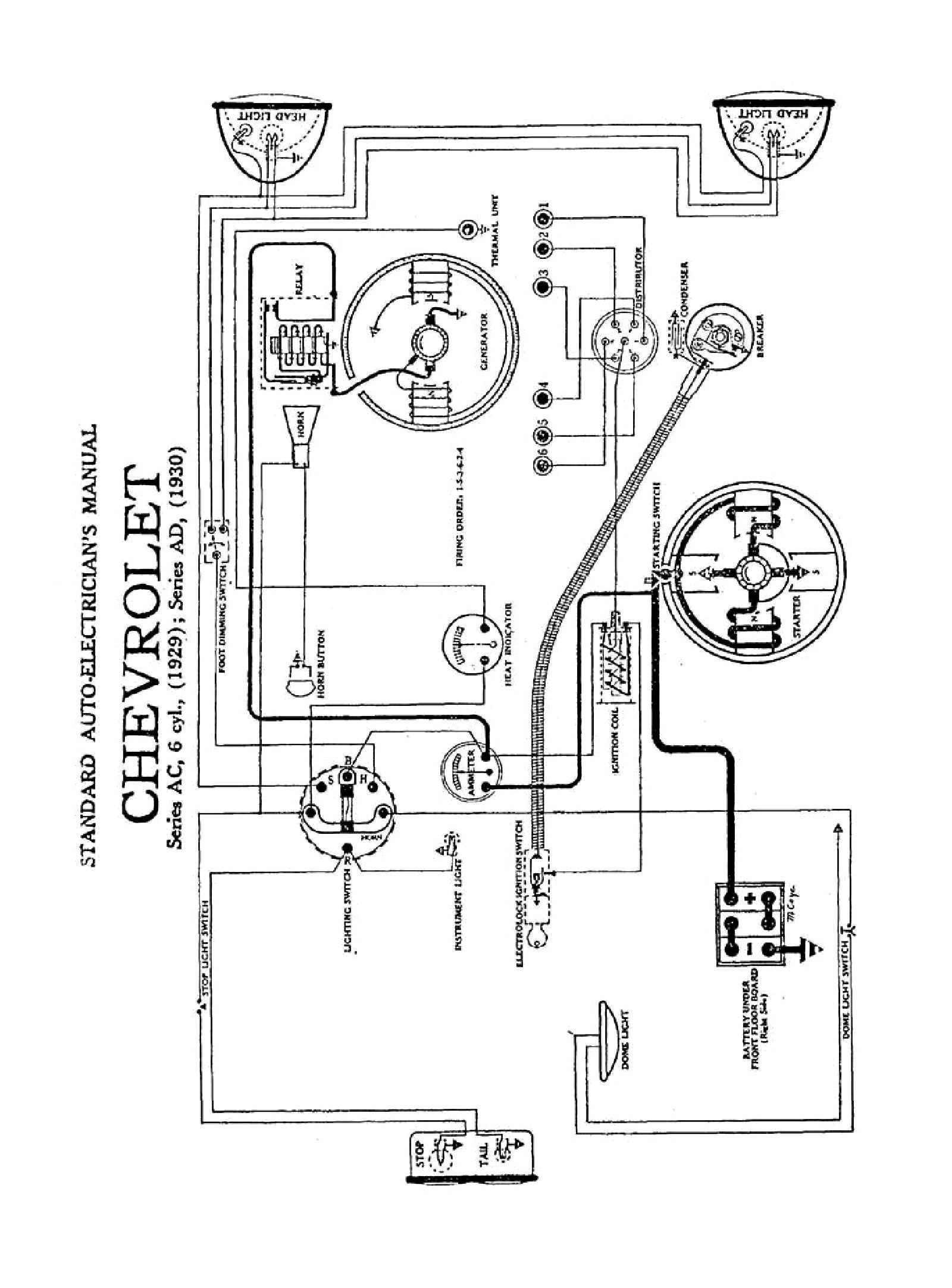
Terminal box reproduction vs original The model a is positive ground and the model t is negative ground. Ignition coil distributor wiring diagram, size: A schematic diagram is a graphical representation of electrical circuits and typically does not show installation details. Typical wiring diagram (without cowl lamps) beginning in february 1929.
 Source: annawiringdiagram.com
In november 1929 the service bulletins shows the wiring changed so the driver’s side of the coil now is the negative power side terminal and the passenger side terminal will lead to the points, and + ground. I am curious of the readings of a good coil from the top button to the bottom button. Wiring diagram of 240sx ignition 94 basic electrical. The problem truly is that all car is different. Typical wiring diagram (without cowl lamps) beginning in february 1929.
 Source: annawiringdiagram.com
Thanks to john brady for. Ifany of the original wire,as supplied, must be replaced, use the same or equivalent type wire. Model t schematic and wiring diagrams december 2, 2018 version 1.1 by bob cascisa i created four schematic diagrams for the model t electrical system. 800 x 600 px, source: The coil is preferably an internal resistor type but an external resistor will work.
 Source: wiringforums.com
Note that this image is the corrected version, not the one commonly seen on the internet having the internal mistake in the starting motor brush connections. The problem truly is that all car is different. Use copper wire (75ºc min) only between disconnect switch and unit. The wiring is really quite simple, as shown in this schematic taken from model petrol engines, by the late edgar t westbury. A wiring diagram is a simplified traditional pictorial depiction of an electrical circuit.
This site is an open community for users to do sharing their favorite wallpapers on the internet, all images or pictures in this website are for personal wallpaper use only, it is stricly prohibited to use this wallpaper for commercial purposes, if you are the author and find this image is shared without your permission, please kindly raise a DMCA report to Us.
If you find this site helpful, please support us by sharing this posts to your own social media accounts like Facebook, Instagram and so on or you can also save this blog page with the title model a coil wiring diagram by using Ctrl + D for devices a laptop with a Windows operating system or Command + D for laptops with an Apple operating system. If you use a smartphone, you can also use the drawer menu of the browser you are using. Whether it’s a Windows, Mac, iOS or Android operating system, you will still be able to bookmark this website.
Category
Related By Category
- Predator 670 engine wiring diagram Idea
- Frsky x8r wiring diagram information
- Pioneer ts wx130da wiring diagram Idea
- Johnson 50 hp wiring diagram Idea
- Kohler voltage regulator wiring diagram Idea
- Johnson 50 hp outboard wiring diagram information
- Kti hydraulic remote wiring diagram Idea
- Pyle plpw12d wiring diagram information
- Tx9600ts wiring diagram information
- Lifan 50cc wiring diagram information