Microstep driver wiring diagram information
Home » Trend » Microstep driver wiring diagram information
Your Microstep driver wiring diagram images are available. Microstep driver wiring diagram are a topic that is being searched for and liked by netizens now. You can Find and Download the Microstep driver wiring diagram files here. Download all royalty-free photos and vectors.
If you’re looking for microstep driver wiring diagram images information connected with to the microstep driver wiring diagram keyword, you have pay a visit to the right blog. Our site always gives you hints for viewing the maximum quality video and picture content, please kindly surf and locate more enlightening video content and graphics that fit your interests.
Microstep Driver Wiring Diagram. • voltage regulated spindle speed controlled by parallel interface as function of supply voltage. Microstep steps/rev.(for1.8°motor) sw5 sw6 sw7 sw8 2 400 4 800 8 1600 16 3200 32 6400 64 12800 128 25600 5 1000 10 2000 20 4000 25 5000 40 8000 50 10000 100 20000 125 25000. When the charged motor stops, there is still a large current flowing through the coil. Speed and torque will depend on winding inductance.
 CNC Kit 3Axis Nema23 Stepper Motor M335 Stepper Driver For From ebay.com
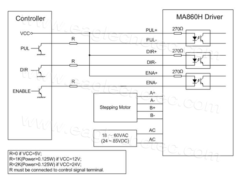
High level (npn control signal, pnp and differential control signals are on the contrary, namely low level for enabling.) for enabling the driver and low level for disabling the driver. Tb6600 stepper motor driver / controller vcc pin (red wire in the diagram). High level for enabling the driver and low level for disabling the driver. It supports speed and direction control. Speed and torque will depend on winding dm556 digital stepping driver manual v1.0 tel: 4)it is forbidden to plug and unplug the driver�s strong p2 terminal.
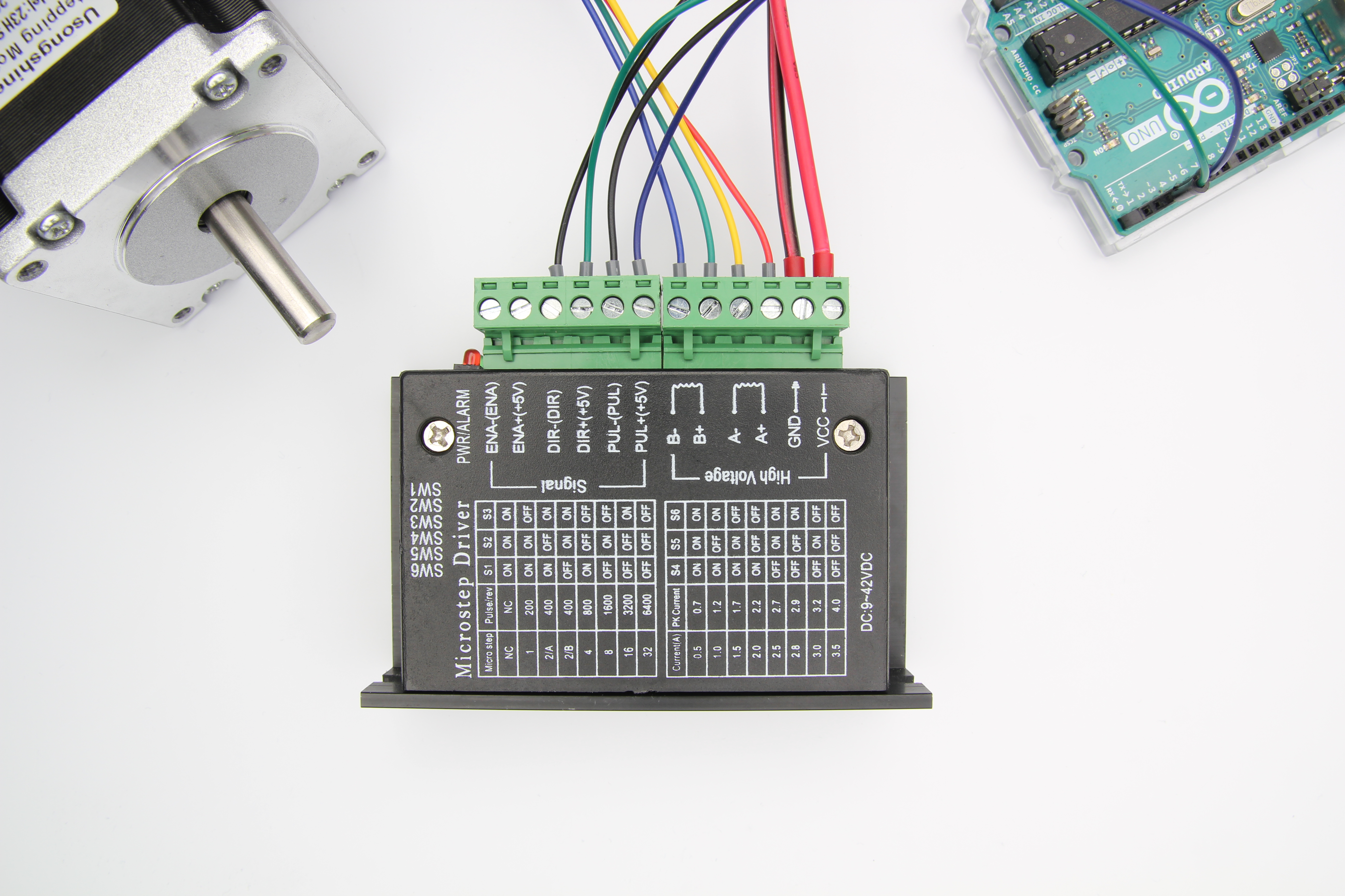
There are 7 kinds of micro steps (1, 2 / a, 2 / b, 4, 8, 16, 32) and 8 kinds of current control (0.5a, 1a, 1.5a, 2a, 2.5a, 2.8a, 3.0a, 3.5a) in all.
Wiring for nema 24 stepping motor to microstep driver cw230. It supports speed and direction control. 4)it is forbidden to plug and unplug the driver�s strong p2 terminal. Speed and torque will depend on winding inductance. In general, the larger the microstep divisor provided, the more costly the stepper motor driver. Typically, microstep modes range from divide‐by‐10 to divide‐by‐256 (51,200 steps/rev for a 1.8 degree motor).
 Source: openbuilds.com
This example can be used to let the motor spin continuously. Pc’s control signals can be active in high and low electrical level. • suitable for unipolar or bipolar stepper motors. Some microstep drivers have a fixed divisor, while the more expensive microstep drivers provide for selectable divisors. • voltage regulated spindle speed controlled by parallel interface as function of supply voltage.
 Source: archive.fabacademy.org
Wiring for nema 24 stepping motor to microstep driver cw230. You can set its micro step and output current with 6 dip switches. Speed and torque will depend on winding inductance. Wire 1 to wire 2 to wire 3 to wire g/y to screened see page 3 cable g/y = green and yellow warning never disconnect stepper from driver while power is switched on as output mosfets will be damaged. The wiring diagram below shows you which connections you need to make.
 Source: ebay.com.au
Two wires for a coil to the driver will reverse motion direction. In setting the driver output current, multiply the specified phase current by 1.4 to determine the peak output current. Speed and torque will depend on winding inductance. 4 lead motors are the least flexible but easiest to wire. Wiring the stepper motor to the cw230 driver, wiring the cw230 driver to the parallel.
 Source: pinterest.com.au
The output of the 3.3 vdc dc to dc converter is routed to pins 2, 4 and 6 of the tb6600 stepper motor driver / controller (blue wire in the diagram). Wiring the stepper motor to the cw230 driver, wiring the cw230 driver to the parallel. Wire 1 to wire 2 to wire 3 to wire g/y to screened see page 3 cable g/y = green and yellow warning never disconnect stepper from driver while power is switched on as output mosfets will be damaged. 4)it is forbidden to plug and unplug the driver�s strong p2 terminal. Some microstep drivers have a fixed divisor, while the more expensive microstep drivers provide for selectable divisors.
 Source: in.pinterest.com
This driver is easy to use and can control large stepper motors like a 3 a nema 23. Do not use fuses or isolation switches between driver and stepper as disconnection arks can damage output mosfets tel: Speed and torque will depend on winding inductance. Speed and torque will depend on winding dm556 digital stepping driver manual v1.0 tel: Microstep steps/rev.(for1.8°motor) sw5 sw6 sw7 sw8 2 400 4 800 8 1600 16 3200 32 6400 64 12800 128 25600 5 1000 10 2000 20 4000 25 5000 40 8000 50 10000 100 20000 125 25000.
 Source: diagramweb.net
This signal is used for enabling/disabling the driver. Two wires for a coil to the driver will reverse motion direction. The output of the 3.3 vdc dc to dc converter is routed to pins 2, 4 and 6 of the tb6600 stepper motor driver / controller (blue wire in the diagram). In general, the larger the microstep divisor provided, the more costly the stepper motor driver. Some microstep drivers have a fixed divisor, while the more expensive microstep drivers provide for selectable divisors.
 Source: eaglecnctec.com
Wiring the stepper motor to the cw230 driver, wiring the cw230 driver to the parallel. Wire 1 to wire 2 to wire 3 to wire g/y to screened see page 3 cable g/y = green and yellow warning never disconnect stepper from driver while power is switched on as output mosfets will be damaged. Stepper motor driver 7.8a dq860ma. In setting the driver output current, multiply the specified phase current by 1.4 to determine the peak output current. This example can be used to let the motor spin continuously.
 Source: lasergods.com
Pulling the p2 terminal will cause a huge moment to induce the electromotive force to burn the driver. Tb6600 stepper motor driver / controller vcc pin (red wire in the diagram). The circuit that it adopts is smiliar to the circuit of a servo controller which enables the motor to run. In setting the driver output current, multiply the specified phase current by 1.4 to determine the peak output current. Cw5045 wiring diagram information is specific to our products and can cause damage if used with none compatible products so please check with your supplier for.
 Source: ebay.com
Wiring diagrams for 4/6/8 leads motors i. Usually left unconnected (enabled) 2) pins wiring diagram: Microstep steps/rev.(for1.8°motor) sw5 sw6 sw7 sw8 2 400 4 800 8 1600 16 3200 32 6400 64 12800 128 25600 5 1000 10 2000 20 4000 25 5000 40 8000 50 10000 100 20000 125 25000. • voltage regulated spindle speed controlled by parallel interface as function of supply voltage. In general, the larger the microstep divisor provided, the more costly the stepper motor driver.
 Source: forum.arduino.cc
4)it is forbidden to plug and unplug the driver�s strong p2 terminal. Typically, microstep modes range from divide‐by‐10 to divide‐by‐256 (51,200 steps/rev for a 1.8 degree motor). Wiring the stepper motor to the cw230 driver, wiring the cw230 driver to the parallel. • suitable for unipolar or bipolar stepper motors. It is also routed to the input of the 3.3 vdc dc to dc converter (again a red wire in the diagram).
 Source: spark-concepts.com
Do not use fuses or isolation switches between driver and stepper as disconnection arks can damage output mosfets tel: Tb6600 stepper motor driver / controller vcc pin (red wire in the diagram). Cw5045 wiring diagram information is specific to our products and can cause damage if used with none compatible products so please check with your supplier for. High level (npn control signal, pnp and differential control signals are on the contrary, namely low level for enabling.) for enabling the driver and low level for disabling the driver. Wiring diagrams for 4/6/8 leads motors i.
 Source: reprap.me
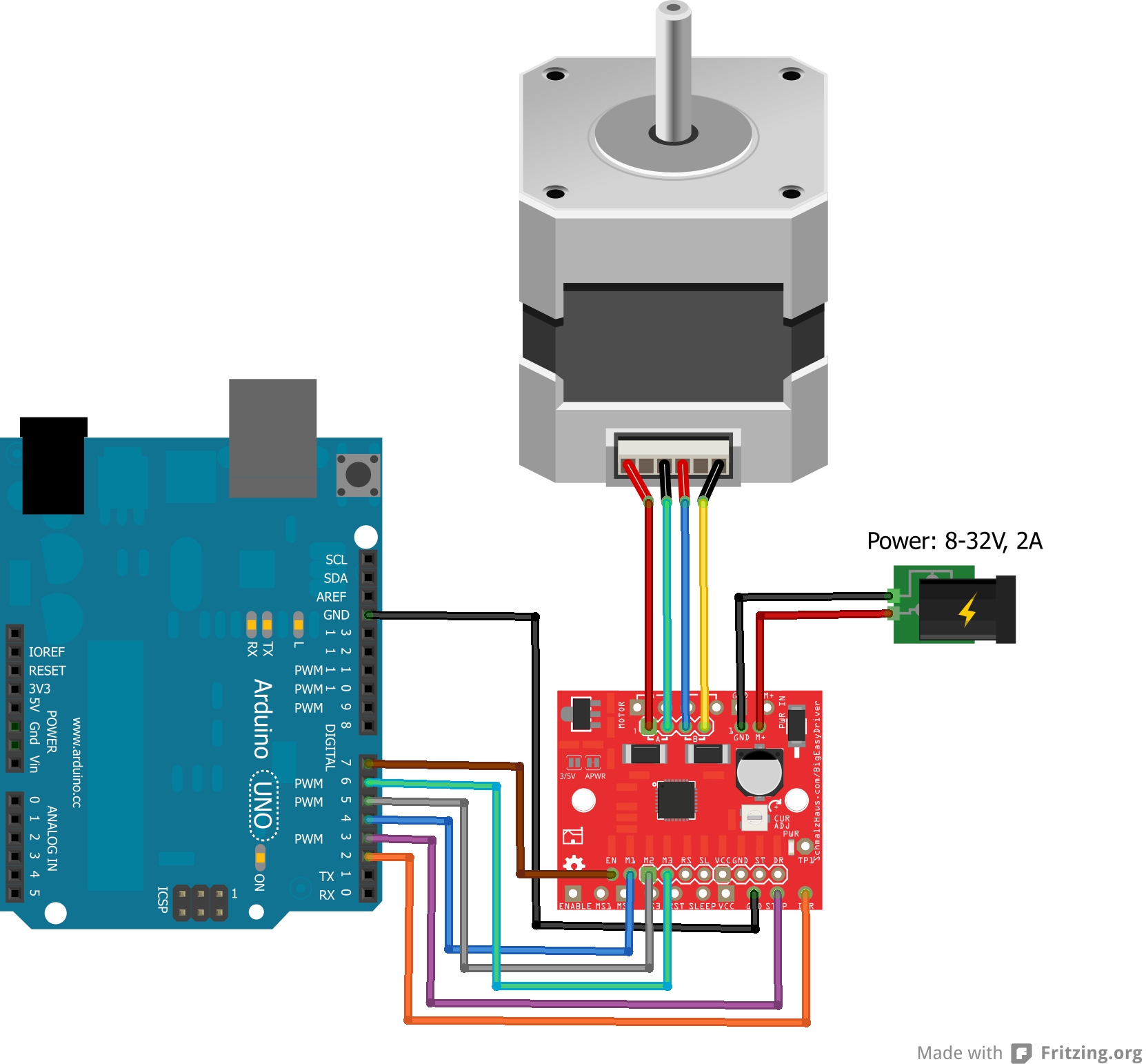
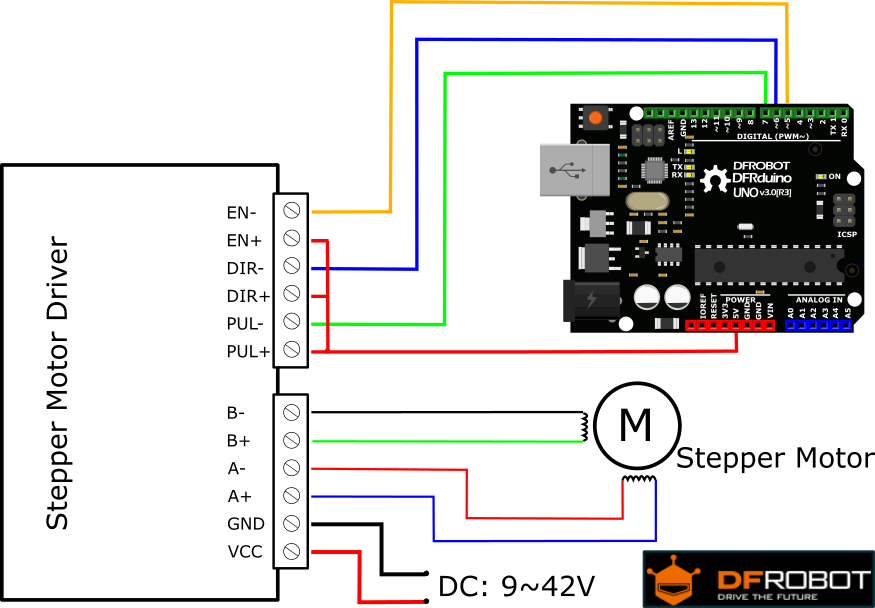
4 lead motors are the least flexible but easiest to wire. Two wires for a coil to the driver will reverse motion direction. I have included a wiring diagram and 3 example codes. 4 lead motors are the least flexible but easiest to wire. 5)it is forbidden to add the tin wire to the terminal after adding the tin wire.
 Source: sinoning.com
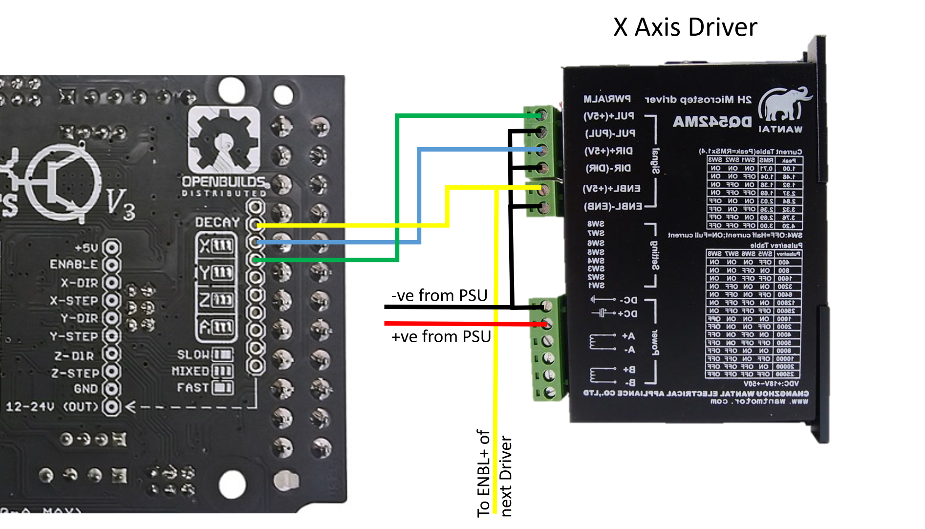
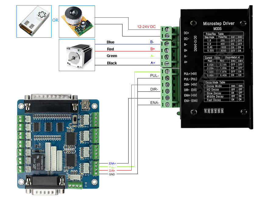
This signal is used for enabling/disabling the driver. This signal is used for enabling/disabling the driver. Cw5045 wiring diagram information is specific to our products and can cause damage if used with none compatible products so please check with your supplier for. Microstep steps/rev.(for1.8°motor) sw5 sw6 sw7 sw8 2 400 on on on on 4 800 on off on on 8 1600 on on off on 16 3200 on off off on 32 6400 on on on off 64 12800 on off on off 128 25600 on on off off 256 51200 on off off off 5 1000 off on on on 10 2000 off off on on 25 5000 off on off on 50 10000 off off off on 125 25000 off on on off 250 50000. The wiring diagram below shows you which connections you need to make.
 Source: ebay.fr
High level for enabling the driver and low level for disabling the driver. There are 7 kinds of micro steps (1, 2 / a, 2 / b, 4, 8, 16, 32) and 8 kinds of current control (0.5a, 1a, 1.5a, 2a, 2.5a, 2.8a, 3.0a, 3.5a) in all. 5)it is forbidden to add the tin wire to the terminal after adding the tin wire. It is also routed to the input of the 3.3 vdc dc to dc converter (again a red wire in the diagram). Wiring diagrams for 4/6/8 leads motors i.
 Source: robotgear.com.au
Microstep steps/rev.(for1.8°motor) sw5 sw6 sw7 sw8 2 400 on on on on 4 800 on off on on 8 1600 on on off on 16 3200 on off off on 32 6400 on on on off 64 12800 on off on off 128 25600 on on off off 256 51200 on off off off 5 1000 off on on on 10 2000 off off on on 25 5000 off on off on 50 10000 off off off on 125 25000 off on on off 250 50000. Pc’s control signals can be active in high and low electrical level. Cw5045 wiring diagram information is specific to our products and can cause damage if used with none compatible products so please check with your supplier for. Speed and torque will depend on winding inductance. Wiring instructions there are three input signals in all:
 Source: makerguides.com
5)it is forbidden to add the tin wire to the terminal after adding the tin wire. 4 lead motors are the least flexible but easiest to wire. The output of the 3.3 vdc dc to dc converter is routed to pins 2, 4 and 6 of the tb6600 stepper motor driver / controller (blue wire in the diagram). There are 7 kinds of micro steps (1, 2 / a, 2 / b, 4, 8, 16, 32) and 8 kinds of current control (0.5a, 1a, 1.5a, 2a, 2.5a, 2.8a, 3.0a, 3.5a) in all. • voltage regulated spindle speed controlled by parallel interface as function of supply voltage.
 Source: wiki.dfrobot.com
Usually left unconnected (enabled) 2) pins wiring diagram: I have included a wiring diagram and 3 example codes. Usually left unconnected (enabled) 2) pins wiring diagram: Wiring diagrams for 4/6/8 leads motors i. Microstep steps/rev.(for1.8°motor) sw5 sw6 sw7 sw8 2 400 on on on on 4 800 on off on on 8 1600 on on off on 16 3200 on off off on 32 6400 on on on off 64 12800 on off on off 128 25600 on on off off 256 51200 on off off off 5 1000 off on on on 10 2000 off off on on 25 5000 off on off on 50 10000 off off off on 125 25000 off on on off 250 50000.
 Source: 3ddanang.net
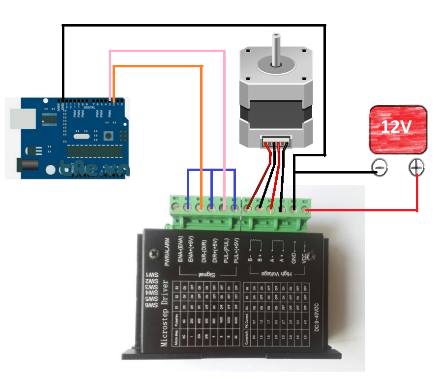
It is also routed to the input of the 3.3 vdc dc to dc converter (again a red wire in the diagram). High level (npn control signal, pnp and differential control signals are on the contrary, namely low level for enabling.) for enabling the driver and low level for disabling the driver. Speed and torque will depend on winding dm556 digital stepping driver manual v1.0 tel: • voltage regulated spindle speed controlled by parallel interface as function of supply voltage. Cw5045 wiring diagram information is specific to our products and can cause damage if used with none compatible products so please check with your supplier for.
This site is an open community for users to submit their favorite wallpapers on the internet, all images or pictures in this website are for personal wallpaper use only, it is stricly prohibited to use this wallpaper for commercial purposes, if you are the author and find this image is shared without your permission, please kindly raise a DMCA report to Us.
If you find this site helpful, please support us by sharing this posts to your preference social media accounts like Facebook, Instagram and so on or you can also bookmark this blog page with the title microstep driver wiring diagram by using Ctrl + D for devices a laptop with a Windows operating system or Command + D for laptops with an Apple operating system. If you use a smartphone, you can also use the drawer menu of the browser you are using. Whether it’s a Windows, Mac, iOS or Android operating system, you will still be able to bookmark this website.
Category
Related By Category
- Predator 670 engine wiring diagram Idea
- Frsky x8r wiring diagram information
- Pioneer ts wx130da wiring diagram Idea
- Johnson 50 hp wiring diagram Idea
- Kohler voltage regulator wiring diagram Idea
- Johnson 50 hp outboard wiring diagram information
- Kti hydraulic remote wiring diagram Idea
- Pyle plpw12d wiring diagram information
- Tx9600ts wiring diagram information
- Lifan 50cc wiring diagram information