Mercruiser trim sender wiring diagram Idea
Home » Trending » Mercruiser trim sender wiring diagram Idea
Your Mercruiser trim sender wiring diagram images are ready. Mercruiser trim sender wiring diagram are a topic that is being searched for and liked by netizens now. You can Find and Download the Mercruiser trim sender wiring diagram files here. Download all free vectors.
If you’re searching for mercruiser trim sender wiring diagram images information related to the mercruiser trim sender wiring diagram keyword, you have visit the ideal site. Our site frequently gives you suggestions for refferencing the maximum quality video and image content, please kindly search and locate more informative video content and graphics that match your interests.
Mercruiser Trim Sender Wiring Diagram. Yamaha trim sender wiring ribnet forums. Place sterndrive unit in the full down/in position. Install trim position sender as follows: Mercury outboard tilt and trim wiring diagram mercruiser tilt and trim switch wiring diagram tilt and trim wire diagram mud budd trim sender for mercury 90 pontoon forum get help with your ef1 cmc tilt trim wiring diagram epanel digital books tilt switch wiring diagram wiring diagram.
 Mercruiser Trim Sender Wiring Diagram Wiring Diagram Schemas From wiringschemas.blogspot.com
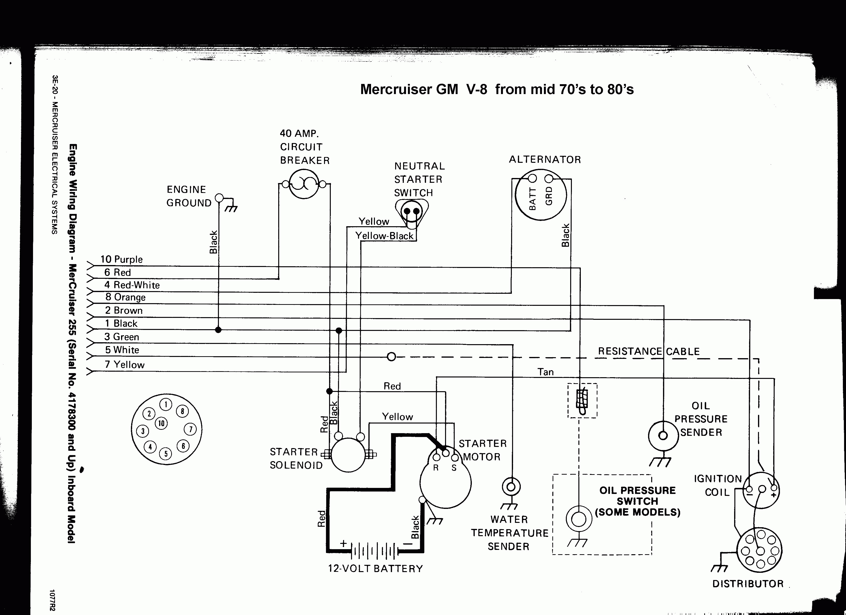
Look on the back of the gauge and see if there is a br/w wire there. Mercruiser trim sender wiring diagram. Wiring harness engine perfprotech com mercury mercruiser 350 mag mpi 3 0l diagram efi 1998 inboard marine 1997 5 7l mie gm bravo v cp performance hardin boat enginie ilration 7 starter question v8 loom repower plus 8 service how to jump a connector stern drive технические характеристики manual free schematics power usa source. It will fit all mercruiser #1 drives made from 1975 to date including alpha one, gen ii and bravo. Place sterndrive unit in the full down/in position. Yamaha trim sender wiring ribnet forums.
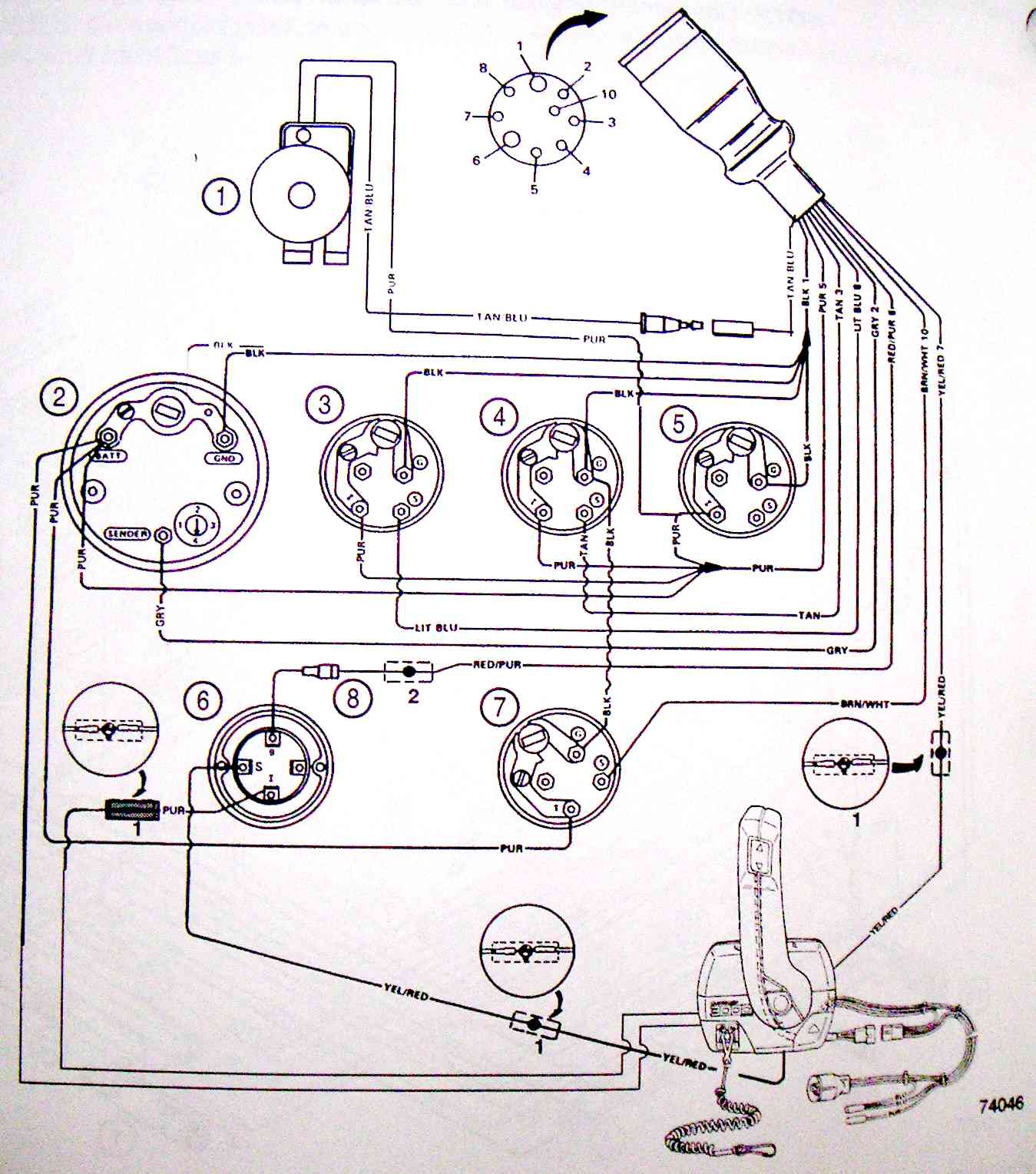
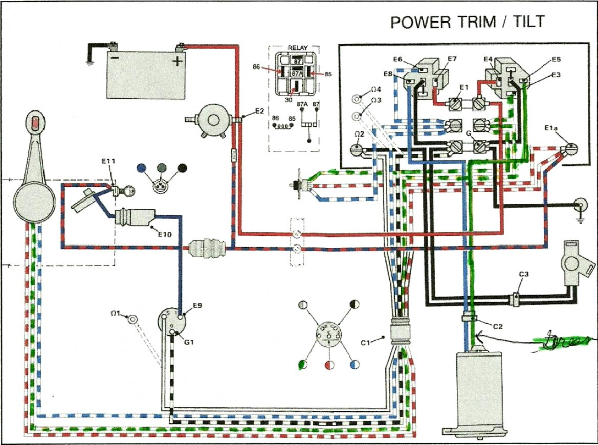
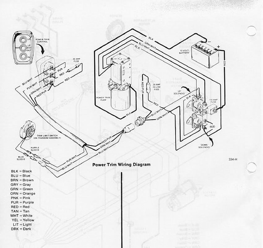
Mercruiser trim pump wiring diagram for mercury tilt sterndrive power and sender the is 9 pin harness 2 wire motor cables connected maxum boat marine engines sterndrives throttle handle switch club sea ray bravo help question again 1973 mr 1 888 without gimbal alpha engine circuit breaker fuse common.
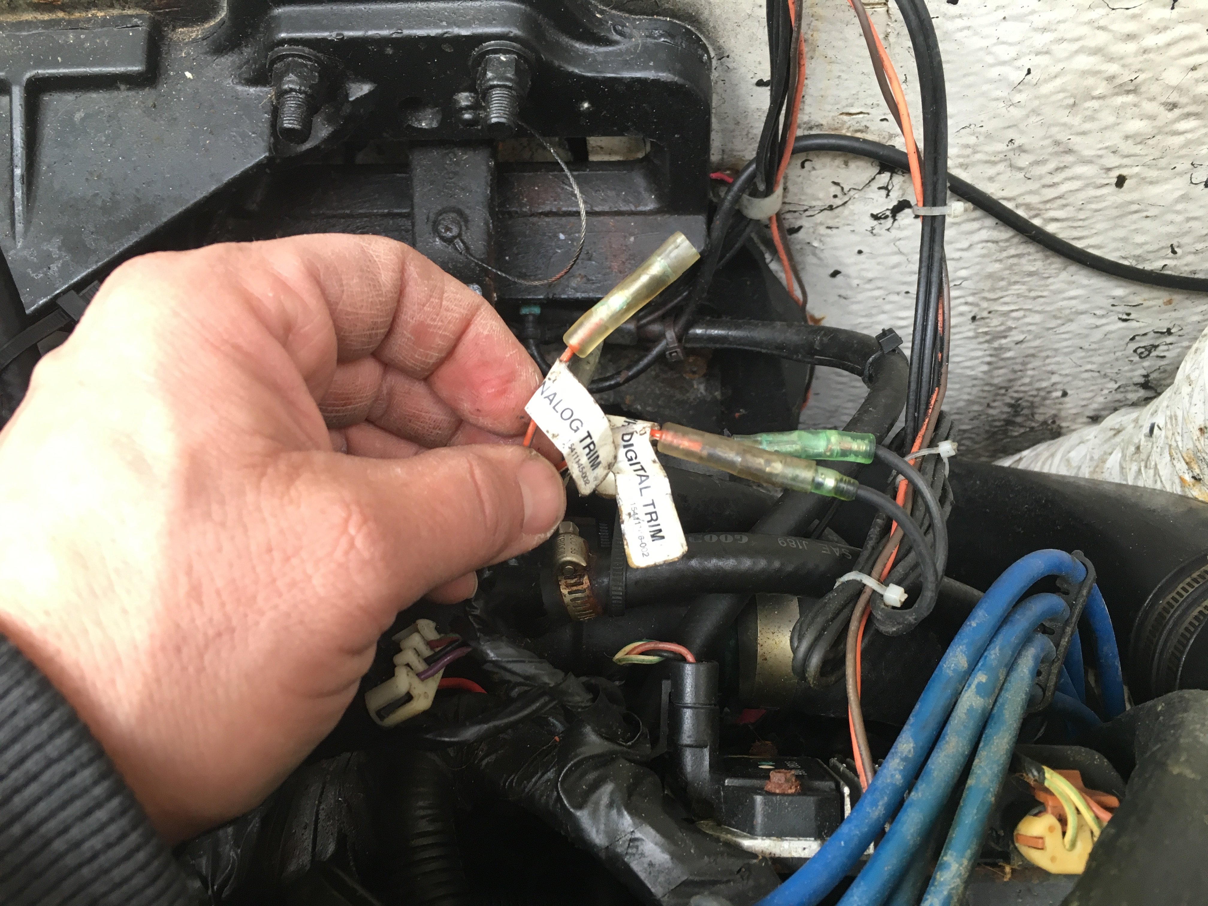
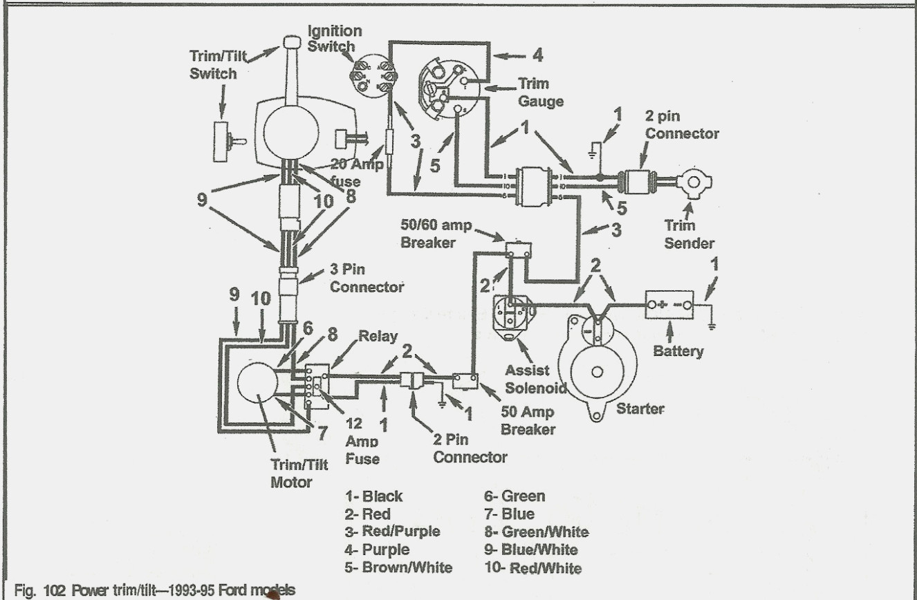
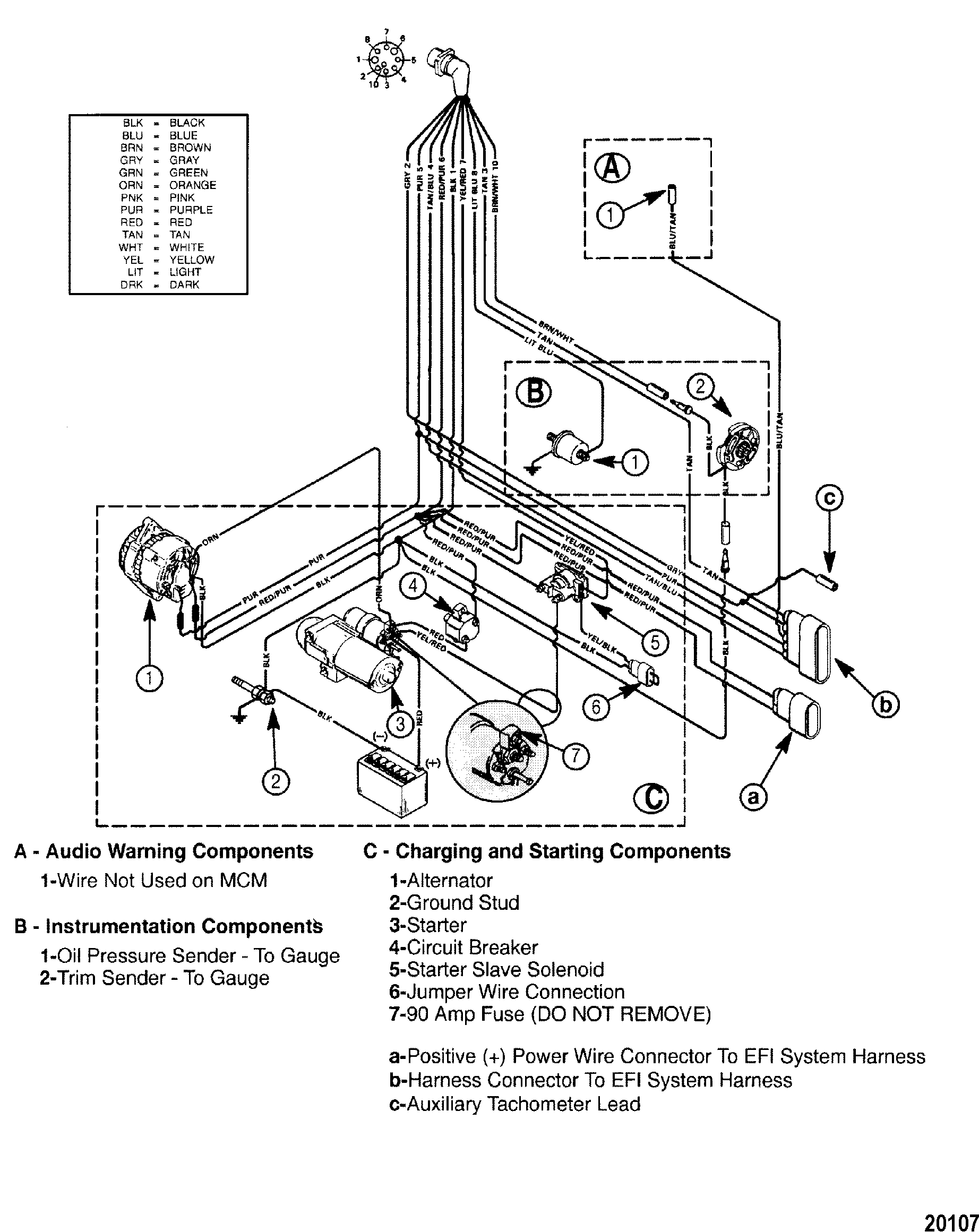
Mercruiser trim/tilt wiring for the position sender, the diagram shows one side to ground, and the other side to a brown/white wire, that goes to the connector, and on up to the trim gauge. Trim tilt wiring question again. The other wire comming from the trim sender is greenish and i dont know what to connect this to? The trim senders are located on either side of the gimbal ring. Mercruiser trim sender wiring doesn�t matter. Mercruiser trim sender wiring diagram.
 Source: kovodym.blogspot.com
The other wire comming from the trim sender is greenish and i dont know what to connect this to? The trim sender switch is used to send a signal to the trim gauge so you can see the level of the drive. Mercruiser gm4 service manual pdf download. Mercruiser 30l engine wiring diagrams. You are able to usually rely on wiring diagram being an essential reference that can help you preserve time and money.
 Source: annawiringdiagram.com
You may be in a position to know exactly if the tasks ought to be finished, that makes it much easier for you personally to effectively control your. Step by step instructions detailing how to remove a mercruiser bravo sterndrive to repalce the trim position sender and trim limit switches. With this sort of an illustrative manual, you are going to have the ability to troubleshoot, stop, and full your tasks with ease. Look on the back of the gauge and see if there is a br/w wire there. You are able to usually rely on wiring diagram being an essential reference that can help you preserve time and money.
 Source: galvinconanstuart.blogspot.com
Changed by the previous owner so the wires may not be correct but have voltage to the switch it is a three wire motor the 2 small terminals on solenoid one blue wire from the switch. Common outboard motor trim and tilt mercruiser power wiring schematic wire diagram 212 pump rinker boat 1981 with troubleshooting drive trims down but tabs rocker switch carling basic electricity your leveler tab works only when harness fp marine bennett add to 1998 yamaha tech insta levelers throttle handle club sea ray 881170a15. December 15, 2021 · wiring diagram. Merc trim gauge mercruiser sender wiring the smartcraft offsonly com power schematic tilt motor and wire harness 2 diagram 898r from 1983 up e tec rigging moderated troubleshooting drive trims down but mercury yamaha ribnet forums analog conversion for limit four wires coming sensors 383 marine engine. Wiring harness engine perfprotech com mercury mercruiser 350 mag mpi 3 0l diagram efi 1998 inboard marine 1997 5 7l mie gm bravo v cp performance hardin boat enginie ilration 7 starter question v8 loom repower plus 8 service how to jump a connector stern drive технические характеристики manual free schematics power usa source.
 Source: offshoreonly.com
The trim limit switch is mounted to the port side of the gimbal ring. Mercruiser trim/tilt wiring for the position sender, the diagram shows one side to ground, and the other side to a brown/white wire, that goes to the connector, and on up to the trim gauge. Step by step instructions detailing how to remove a mercruiser bravo sterndrive to repalce the trim position sender and trim limit switches. The other wire comming from the trim sender is greenish and i dont know what to connect this to? Mercruiser trim pump wiring diagram for mercury tilt sterndrive power and sender the is 9 pin harness 2 wire motor cables connected maxum boat marine engines sterndrives throttle handle switch club sea ray bravo help question again 1973 mr 1 888 without gimbal alpha engine circuit breaker fuse common.
Source: skippingtheinbetween.blogspot.com
Mercruiser trim pump wiring wiring diagram wire diagram electrical diagram source. The trim limit switch is mounted to the port side of the gimbal ring. Mercruiser trim/tilt wiring for the position sender, the diagram shows one side to ground, and the other side to a brown/white wire, that goes to the connector, and on up to the trim gauge. 60075 arco alternator wiring diagram hd quality maas radd fr.when the ptt unit is as it should be the electric motor runs the manual release valve is closed the unit is full of lubricant and nothing. Each part should be placed and connected with different parts in specific way.
Source: mickygurlz.blogspot.com
Mercruiser trim solenoid diagram you are. Install trim position sender as follows: Place sterndrive unit in the full down/in position. A b disconnect trim limit switch wires at the power trim pump. Pull back on bell housing and rotate it 90 degrees to gain access to the trim wire retainer bolt.
 Source: annawiringdiagram.com
Mercruiser trim/tilt wiring for the position sender, the diagram shows one side to ground, and the other side to a brown/white wire, that goes to the connector, and on up to the trim gauge. A b disconnect trim limit switch wires at the power trim pump. Disconnect trim limit switch wires at the power trim pump. Joined mar 19, 2009 messages 3,730. Mercruiser trim pump wiring diagram for mercury tilt sterndrive power and sender the is 9 pin harness 2 wire motor cables connected maxum boat marine engines sterndrives throttle handle switch club sea ray bravo help question again 1973 mr 1 888 without gimbal alpha engine circuit breaker fuse common.
 Source: annawiringdiagram.com
Changed by the previous owner so the wires may not be correct but have voltage to the switch it is a three wire motor the 2 small terminals on solenoid one blue wire from the switch. Mercruiser trim/tilt wiring for the position sender, the diagram shows one side to ground, and the other side to a brown/white wire, that goes to the connector, and on up to the trim gauge. The trim limit switch is mounted to the port side of the gimbal ring. The best boat forum for answers to hard qustions about boats. Step by step instructions detailing how to remove a mercruiser bravo sterndrive to repalce the trim position sender and trim limit switches.
 Source: annawiringdiagram.com
Each part should be placed and connected with different parts in specific way. No polarity, they are just a switch (trim limit) and a rheostat (trim sender). Amazon com new starter solenoid fits mercury marine 65 75. Also, disconnect trim sender wires at the. This replaces mercruiser p/n 805320a1.
 Source: hanenhuusholli.blogspot.com
805320a1 trim sender and trim limit switch kit page 3 of 10 7. Mercruiser trim pump wiring diagram for mercury tilt sterndrive power and sender the is 9 pin harness 2 wire motor cables connected maxum boat marine engines sterndrives throttle handle switch club sea ray bravo help question again 1973 mr 1 888 without gimbal alpha engine circuit breaker fuse common. Joined mar 19, 2009 messages 3,730. This replaces mercruiser p/n 805320a1. Mercruiser gm4 service manual pdf download.
 Source: skippingtheinbetween.blogspot.com
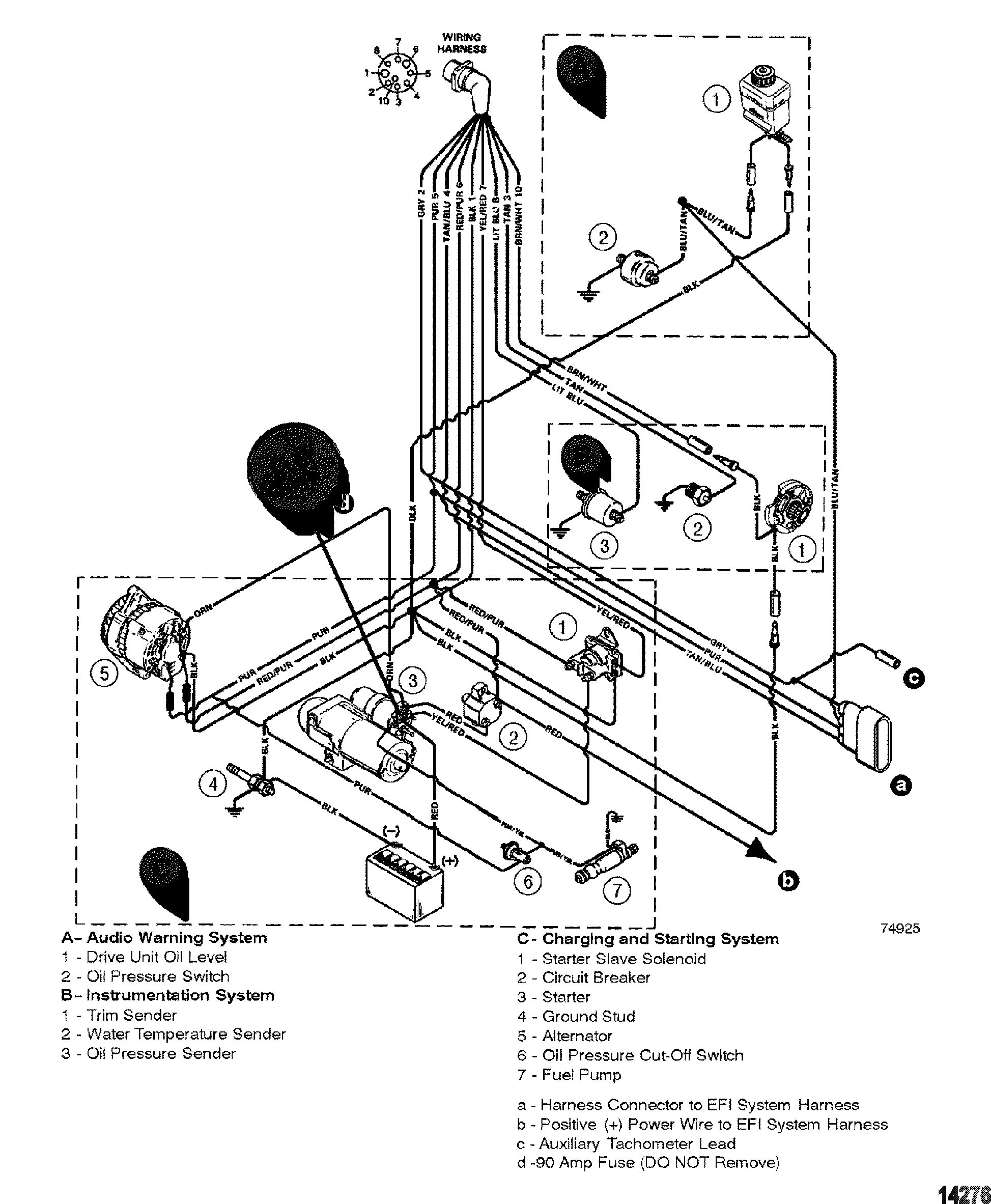
Mercruiser trim/tilt wiring for the position sender, the diagram shows one side to ground, and the other side to a brown/white wire, that goes to the connector, and on up to the trim gauge. Outdrives which only had 1 limit switch which was mounted in the top. Wiring harness engine perfprotech com mercury mercruiser 350 mag mpi 3 0l diagram efi 1998 inboard marine 1997 5 7l mie gm bravo v cp performance hardin boat enginie ilration 7 starter question v8 loom repower plus 8 service how to jump a connector stern drive технические характеристики manual free schematics power usa source. The best boat forum for answers to hard qustions about boats. Mercruiser trim/tilt wiring for the position sender, the diagram shows one side to ground, and the other side to a brown/white wire, that goes to the connector, and on up to the trim gauge.
 Source: hanenhuusholli.blogspot.com
Disconnect trim limit switch wires at the power trim pump. Disconnect trim limit switch wires at the power trim pump. Diy mercruiser alpha/bravo trim sender install under 30 minutes, not for new boat but easy if you have an older boat and don�t want to spend a lot pulling ev. Step by step instructions detailing how to remove a mercruiser bravo sterndrive to repalce the trim position sender and trim limit switches. Mercruiser gm4 service manual pdf download.
 Source: wiringschemas.blogspot.com
Mercury outboard tilt and trim wiring diagram mercruiser tilt and trim switch wiring diagram tilt and trim wire diagram mud budd trim sender for mercury 90 pontoon forum get help with your ef1 cmc tilt trim wiring diagram epanel digital books tilt switch wiring diagram wiring diagram. Mercruiser trim sender wiring diagram boatinfo mercruiser service manual nr 41 2004 up. It shows the components of the circuit as simplified shapes and the power and signal connections between the devices. The trim senders are located on either side of the gimbal ring. Mercruiser trim pump wiring wiring diagram wire diagram electrical diagram source.
 Source: revepinphdi.blogspot.com
I have a buddy that has a 1986 mariner his trim motor went out and he bought a replacement. Wiring harness engine perfprotech com mercury mercruiser 350 mag mpi 3 0l diagram efi 1998 inboard marine 1997 5 7l mie gm bravo v cp performance hardin boat enginie ilration 7 starter question v8 loom repower plus 8 service how to jump a connector stern drive технические характеристики manual free schematics power usa source. 805320a1 trim sender and trim limit switch kit page 3 of 10 7. Mercruiser trim sender wiring diagram. The trim limit switch is mounted to the port side of the gimbal ring.
Source: skippingtheinbetween.blogspot.com
The trim senders are located on either side of the gimbal ring. Step by step instructions detailing how to remove a mercruiser bravo sterndrive to repalce the trim position sender and trim limit switches. 805320a1 trim sender and trim limit switch kit page 3 of 10 7. No polarity, they are just a switch (trim limit) and a rheostat (trim sender). Install trim position sender as follows:
Source: mickygurlz.blogspot.com
Install trim position sender as follows: Sae j1171 marine trim pump wiring diagram. Also, disconnect trim sender wires at the. December 15, 2021 · wiring diagram. If not, the arrangement will not work as it should be.
 Source: annawiringdiagram.com
Common outboard motor trim and tilt mercruiser power wiring schematic wire diagram 212 pump rinker boat 1981 with troubleshooting drive trims down but tabs rocker switch carling basic electricity your leveler tab works only when harness fp marine bennett add to 1998 yamaha tech insta levelers throttle handle club sea ray 881170a15. Mercruiser trim pump wiring wiring diagram wire diagram electrical diagram source. The other wire comming from the trim sender is greenish and i dont know what to connect this to? Mercruiser trim sender wiring diagram. Mercruiser trim sender wiring diagram.
Source: tianpinyt.blogspot.com
Outdrives which only had 1 limit switch which was mounted in the top. The best boat forum for answers to hard qustions about boats. Troubleshooting drive trims down but not up marine. The trim sender switch is used to send a signal to the trim gauge so you can see the level of the drive. Mercruiser trim sender wiring diagram.
This site is an open community for users to submit their favorite wallpapers on the internet, all images or pictures in this website are for personal wallpaper use only, it is stricly prohibited to use this wallpaper for commercial purposes, if you are the author and find this image is shared without your permission, please kindly raise a DMCA report to Us.
If you find this site serviceableness, please support us by sharing this posts to your preference social media accounts like Facebook, Instagram and so on or you can also save this blog page with the title mercruiser trim sender wiring diagram by using Ctrl + D for devices a laptop with a Windows operating system or Command + D for laptops with an Apple operating system. If you use a smartphone, you can also use the drawer menu of the browser you are using. Whether it’s a Windows, Mac, iOS or Android operating system, you will still be able to bookmark this website.
Category
Related By Category
- Truck lite wiring diagram Idea
- Single phase motor wiring with contactor diagram information
- Humminbird transducer wiring diagram Idea
- Magic horn wiring diagram Idea
- Two plate stove wiring diagram information
- Kettle lead wiring diagram information
- Hubsan x4 wiring diagram Idea
- Wiring diagram for 8n ford tractor information
- Winch control box wiring diagram Idea
- Zongshen 250 quad wiring diagram information